clock CHRYSLER VOYAGER 1996 Service Manual
[x] Cancel search | Manufacturer: CHRYSLER, Model Year: 1996, Model line: VOYAGER, Model: CHRYSLER VOYAGER 1996Pages: 1938, PDF Size: 55.84 MB
Page 79 of 1938
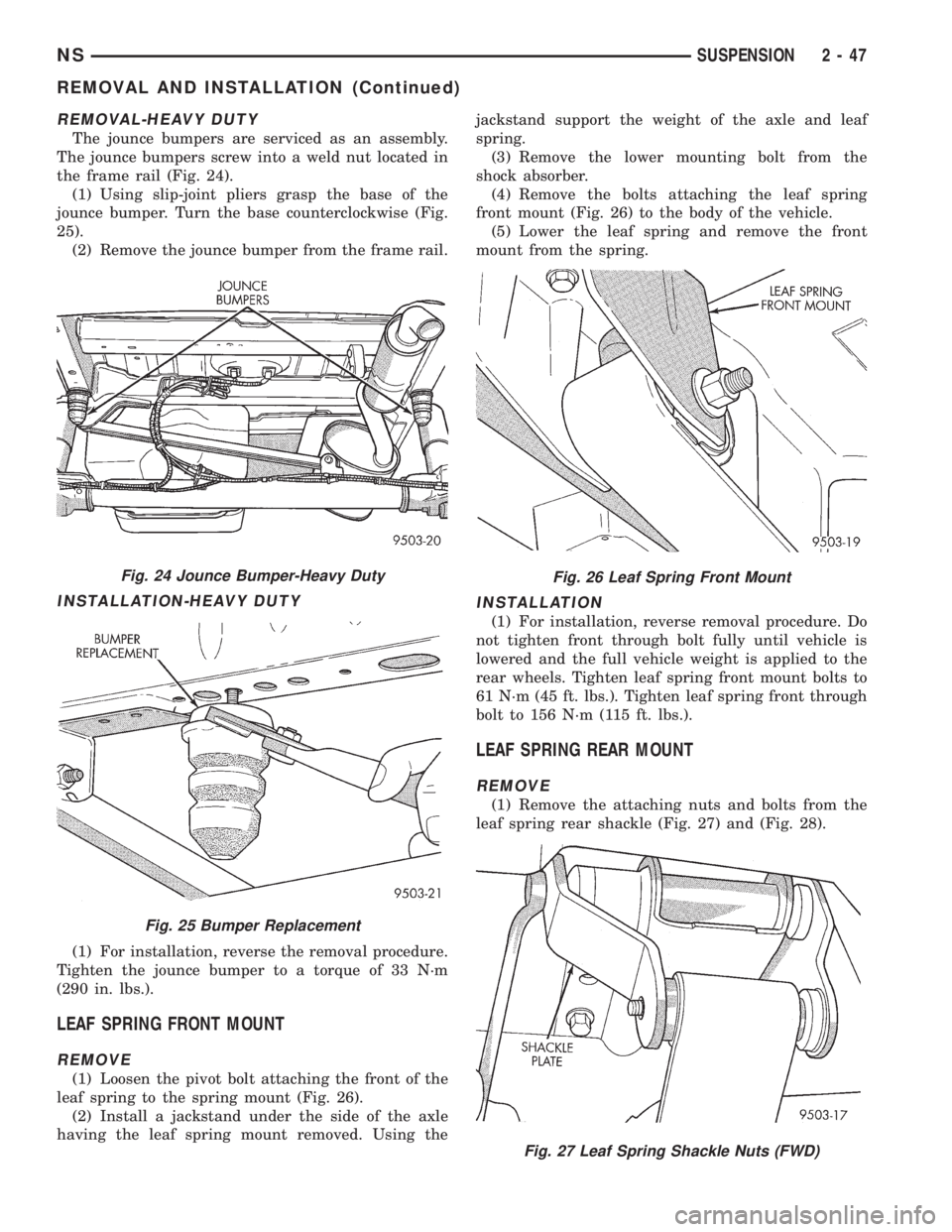
REMOVAL-HEAVY DUTY
The jounce bumpers are serviced as an assembly.
The jounce bumpers screw into a weld nut located in
the frame rail (Fig. 24).
(1) Using slip-joint pliers grasp the base of the
jounce bumper. Turn the base counterclockwise (Fig.
25).
(2) Remove the jounce bumper from the frame rail.
INSTALLATION-HEAVY DUTY
(1) For installation, reverse the removal procedure.
Tighten the jounce bumper to a torque of 33 N´m
(290 in. lbs.).
LEAF SPRING FRONT MOUNT
REMOVE
(1) Loosen the pivot bolt attaching the front of the
leaf spring to the spring mount (Fig. 26).
(2) Install a jackstand under the side of the axle
having the leaf spring mount removed. Using thejackstand support the weight of the axle and leaf
spring.
(3) Remove the lower mounting bolt from the
shock absorber.
(4) Remove the bolts attaching the leaf spring
front mount (Fig. 26) to the body of the vehicle.
(5) Lower the leaf spring and remove the front
mount from the spring.
INSTALLATION
(1) For installation, reverse removal procedure. Do
not tighten front through bolt fully until vehicle is
lowered and the full vehicle weight is applied to the
rear wheels. Tighten leaf spring front mount bolts to
61 N´m (45 ft. lbs.). Tighten leaf spring front through
bolt to 156 N´m (115 ft. lbs.).
LEAF SPRING REAR MOUNT
REMOVE
(1) Remove the attaching nuts and bolts from the
leaf spring rear shackle (Fig. 27) and (Fig. 28).
Fig. 24 Jounce Bumper-Heavy Duty
Fig. 25 Bumper Replacement
Fig. 26 Leaf Spring Front Mount
Fig. 27 Leaf Spring Shackle Nuts (FWD)
NSSUSPENSION 2 - 47
REMOVAL AND INSTALLATION (Continued)
Page 151 of 1938
(4) Insert cable housing retainer into body outrig-
ger bracket making certain that cable housing
retainer fingers lock the housing firmly into place.
(5) Connect rear park brake cable to the equalizer
bracket (Fig. 169).
(6) Install brake drum, and wheel and tire assem-
bly.
(7) Remove the locking pliers from the front park
brake cable. This will automatically adjust the park
brake cables.
(8) Apply and release park brake pedal 1 time,
this will seat the park brake cables.
STOP LAMP SWITCH
REMOVE
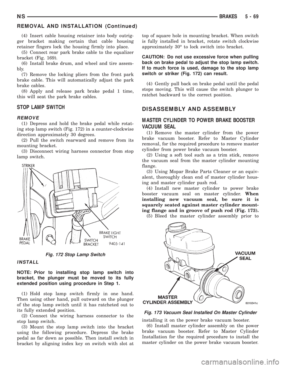
(1) Depress and hold the brake pedal while rotat-
ing stop lamp switch (Fig. 172) in a counter-clockwise
direction approximately 30 degrees.
(2) Pull the switch rearward and remove from its
mounting bracket.
(3) Disconnect wiring harness connector from stop
lamp switch.
INSTALL
NOTE: Prior to installing stop lamp switch into
bracket, the plunger must be moved to its fully
extended position using procedure in Step 1.
(1) Hold stop lamp switch firmly in one hand.
Then using other hand, pull outward on the plunger
of the stop lamp switch until it has ratcheted out to
its fully extended position.
(2) Connect the wiring harness connector to the
stop lamp switch.
(3) Mount the stop lamp switch into the bracket
using the following procedure. Depress the brake
pedal as far down as possible. Then install switch in
bracket by aligning index key on switch with slot attop of square hole in mounting bracket. When switch
is fully installed in bracket, rotate switch clockwise
approximately 30É to lock switch into bracket.
CAUTION: Do not use excessive force when pulling
back on brake pedal to adjust the stop lamp switch.
If to much force is used, damage to the stop lamp
switch or striker (Fig. 172) can result.
(4) Gently pull back on brake pedal until the pedal
stops moving. This will cause the switch plunger to
ratchet backward to the correct position.
DISASSEMBLY AND ASSEMBLY
MASTER CYLINDER TO POWER BRAKE BOOSTER
VACUUM SEAL
(1) Remove the master cylinder from the power
brake vacuum booster. Refer to Master Cylinder
removal, for the required procedure to remove master
cylinder from power brake vacuum booster.
(2) Using a soft tool such as a trim stick, remove
the vacuum seal from the master cylinder mounting
flange.
(3) Using Mopar Brake Parts Cleaner or an equiv-
alent, thoroughly clean end of master cylinder hous-
ing and master cylinder push rod.
(4) Install new master cylinder to power brake
booster vacuum seal on master cylinder.When
installing new vacuum seal, be sure it is
squarely seated against master cylinder mount-
ing flange and in groove of push rod (Fig. 173).
(5) Bleed the master cylinder assembly prior to
installing it on the power brake vacuum booster.
(6) Install master cylinder assembly on the power
brake vacuum booster. Refer to Master Cylinder
Installation for the required procedure to install the
master cylinder on the power brake vacuum booster.
Fig. 172 Stop Lamp Switch
Fig. 173 Vacuum Seal Installed On Master Cylinder
NSBRAKES 5 - 69
REMOVAL AND INSTALLATION (Continued)
Page 160 of 1938
REAR DRUM BRAKE WHEEL CYLINDER
With brake drums removed, inspect the wheel cyl-
inder boots for evidence of a brake fluid leak. Visu-
ally check the boots for cuts, tears, or heat cracks. If
any of these conditions exist, the wheel cylinders
should be completely cleaned, inspected and new
parts installed.
If a wheel cylinder is leaking and the brake lining
material is saturated with brake fluid, the brake
shoes must be replaced.
BRAKE HOSE AND BRAKE LINES INSPECTION
Flexible rubber hose is used at both front brakes
and at the rear axle. Inspection of brake hoses
should be performed whenever the brake system is
serviced and every 7,500 miles or 12 months, which-
ever comes first (every engine oil change). Inspect
hydraulic brake hoses for surface cracking, scuffing,
or worn spots. If the fabric casing of the rubber hose
becomes exposed due to cracks or abrasions in the
rubber hose cover, the hose should be replaced imme-
diately. Eventual deterioration of the hose can take
place with possible burst failure. Faulty installation
can cause twisting, resulting in wheel, tire, or chassis
interference.
The steel brake tubing should be inspected period-
ically for evidence of physical damage or contact with
moving or hot components.
The flexible brake tube sections used on this vehi-
cle in the primary and secondary tubes from the
master cylinder to the ABS hydraulic control unit
connections and the chassis brake tubes between the
hydraulic control unit and the proportioning valve
must also be inspected. This flexible tubing must be
inspected for kinks, fraying and its contact with
other components of the vehicle or contact with the
body of the vehicle.
REAR WHEEL HUB AND BEARING ASSEMBLY
The rear hub and bearing assembly is designed for
the life of the vehicle and should require no mainte-
nance. The following procedure may be used for eval-
uation of bearing condition.
With wheel and brake drum removed, rotate
flanged outer ring of hub. Excessive roughness, lat-
eral play or resistance to rotation may indicate dirt
intrusion or bearing failure. If the rear wheel bear-
ings exhibit these conditions during inspection, the
hub and bearing assembly should be replaced.
Damaged bearing seals and resulting excessive
grease loss may also require bearing replacement.
Moderate grease loss from bearing is considered nor-
mal and should not require replacement of the hub
and bearing assembly.
ADJUSTMENTS
STOP LAMP SWITCH
(1) Remove stop lamp switch from its bracket by
rotating it approximately 30É in a counter-clockwise
direction.
(2) Disconnect wiring harness connector from stop
lamp switch.
(3) Hold stop lamp switch firmly in one hand.
Then using other hand, pull outward on the plunger
of the stop lamp switch until it has ratcheted out to
its fully extended position.
(4) Install the stop lamp switch into the bracket
using the following procedure. Depress the brake
pedal as far down as possible. Then while keeping
the brake pedal depressed, install the stop lamp
switch into the bracket by aligning index key on
switch with slot at top of square hole in mounting
bracket. When switch is fully installed in the square
hole of the bracket, rotate switch clockwise approxi-
mately 30É to lock the switch into the bracket.
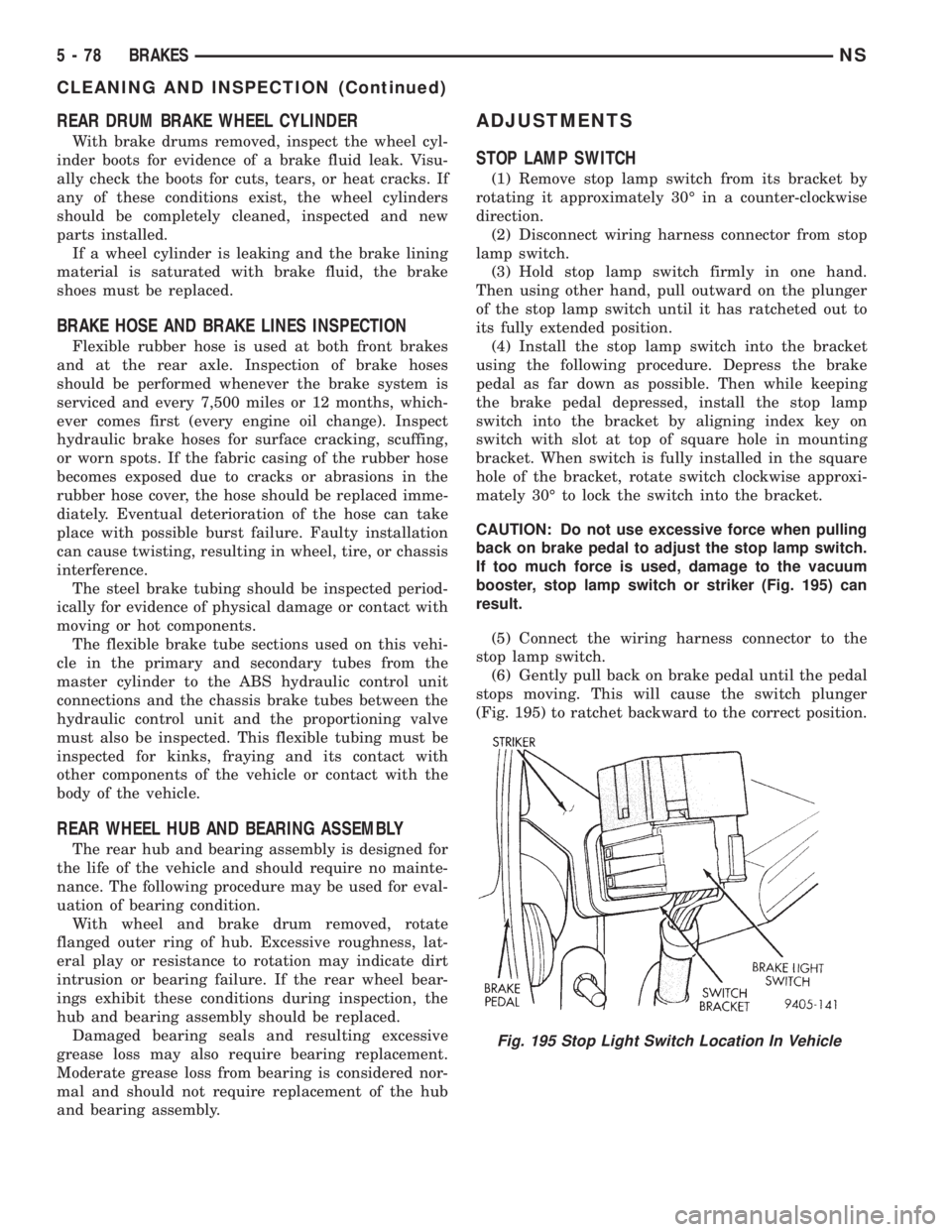
CAUTION: Do not use excessive force when pulling
back on brake pedal to adjust the stop lamp switch.
If too much force is used, damage to the vacuum
booster, stop lamp switch or striker (Fig. 195) can
result.
(5) Connect the wiring harness connector to the
stop lamp switch.
(6) Gently pull back on brake pedal until the pedal
stops moving. This will cause the switch plunger
(Fig. 195) to ratchet backward to the correct position.
Fig. 195 Stop Light Switch Location In Vehicle
5 - 78 BRAKESNS
CLEANING AND INSPECTION (Continued)
Page 163 of 1938
group of the service manual for the installation pro-
cedure.
(13) Install wheel and tire.
(14) Tighten the wheel mounting nuts in the
proper sequence until all nuts are torqued to half the
specified torque. Then repeat the tightening sequence
to the full specified torque of 129 N´m (95 ft. lbs.).
(15) Lower vehicle.
(16) Apply and release the park brake pedal one
time. This will seat and correctly adjust the park
brake cables.
CAUTION: Before moving vehicle, pump brake
pedal several times to ensure the vehicle has a firm
enough pedal to stop the vehicle.
(17) Road test the vehicle to ensure proper func-
tion of the vehicle's brake system.
PARK BRAKE CABLE ADJUSTMENT
The park brake cables on this vehicle have an
automatic self adjuster built into the park brake
pedal mechanism. When the foot operated park brake
pedal is in its released (upward most) position, a
clock spring automatically adjusts the park brake
cables. The park brake cables are adjusted (ten-
sioned) just enough to remove all the slack from the
cables. The automatic adjuster system will not over
adjust the cables causing rear brake drag.
Due to the automatic adjust feature of the park
brake pedal, adjustment of the parking brake cables
on these vehicles relies on proper drum brake and
park brake shoe adjustment. See Rear Brake Adjust-
ment and Park Brake Shoe Adjustment in the Ser-
vice Adjustments Section in this group of the service
manual.
When the park brake pedal is applied the self
adjuster is by-passed and the pedal operates nor-
mally to engage the park brakes.
When a service procedure needs to be performed on
the park brake pedal or the park brake cables, the
automatic self adjuster can be manually locked out
by the service technician.
PROPORTIONING VALVE (HEIGHT SENSING)
Proportioning valve actuator adjustment will be
required if there is a complaint of premature rear
wheel lockup and the front and rear brake shoe lin-
ings checked OK during inspection, the height sens-
ing proportioning valve required replacement, or
there is a complaint of excessive pedal effort and the
vacuum booster and brake pedal checked OK. Make
sure the proportioning valve and the mounting
bracket are firmly attached to the vehicle. Then, pro-
ceed with the following procedure to perform the
adjustment of the actuator.(1) Raise vehicle. Vehicle is to be raised and sup-
ported on jackstands or with a frame contact type
hoist so the rear suspension of the vehicle is hanging
free. See hoisting in the Lubrication And Mainte-
nance section of this service manual.
(2) Remove rear wheels/tires.
(3) Using an appropriate jack, support the rear
axle prior to the removal of the track bar and shock
absorber bolts from the rear axle.
(4) Unbolt the track bar from the rear axle.
(5) Unbolt both shock absorbers from the rear
axle.
(6) Loosen (do not remove) both of the leaf spring
to front spring hanger pivot bolts.
NOTE: When lowering the rear axle be sure that the
leaf springs do not come in contact with the hoist
limiting the downward movement of the axle. If this
occurs an improper adjustment of the actuator may
result.
(7) Lower the rear axle so it is at its farthest point
of downward movement.
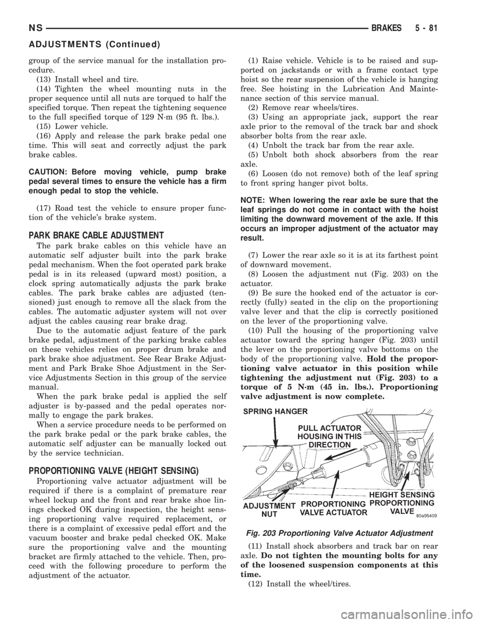
(8) Loosen the adjustment nut (Fig. 203) on the
actuator.
(9) Be sure the hooked end of the actuator is cor-
rectly (fully) seated in the clip on the proportioning
valve lever and that the clip is correctly positioned
on the lever of the proportioning valve.
(10) Pull the housing of the proportioning valve
actuator toward the spring hanger (Fig. 203) until
the lever on the proportioning valve bottoms on the
body of the proportioning valve.Hold the propor-
tioning valve actuator in this position while
tightening the adjustment nut (Fig. 203) to a
torque of 5 N´m (45 in. lbs.). Proportioning
valve adjustment is now complete.
(11) Install shock absorbers and track bar on rear
axle.Do not tighten the mounting bolts for any
of the loosened suspension components at this
time.
(12) Install the wheel/tires.
Fig. 203 Proportioning Valve Actuator Adjustment
NSBRAKES 5 - 81
ADJUSTMENTS (Continued)
Page 210 of 1938
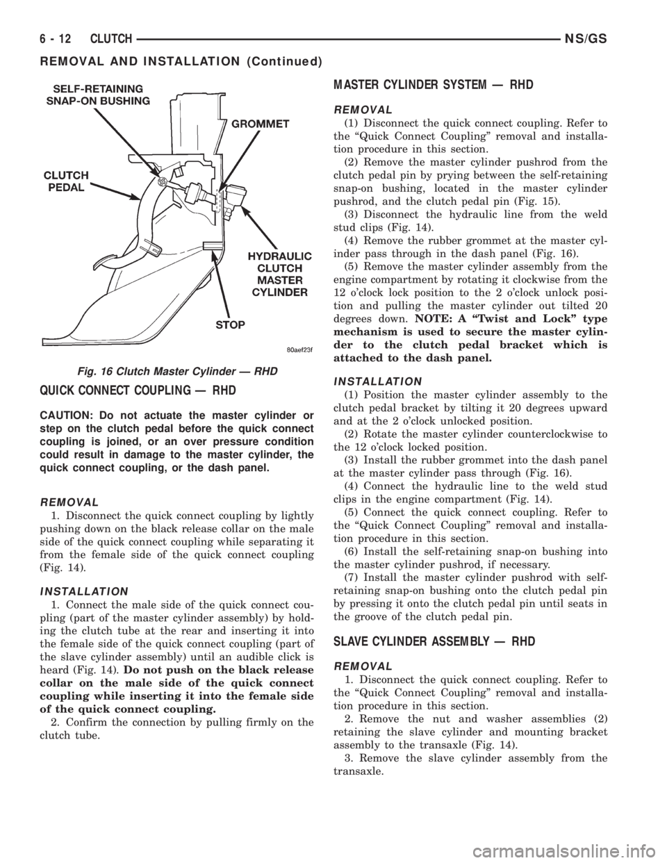
QUICK CONNECT COUPLING Ð RHD
CAUTION: Do not actuate the master cylinder or
step on the clutch pedal before the quick connect
coupling is joined, or an over pressure condition
could result in damage to the master cylinder, the
quick connect coupling, or the dash panel.
REMOVAL
1. Disconnect the quick connect coupling by lightly
pushing down on the black release collar on the male
side of the quick connect coupling while separating it
from the female side of the quick connect coupling
(Fig. 14).
INSTALLATION
1. Connect the male side of the quick connect cou-
pling (part of the master cylinder assembly) by hold-
ing the clutch tube at the rear and inserting it into
the female side of the quick connect coupling (part of
the slave cylinder assembly) until an audible click is
heard (Fig. 14).Do not push on the black release
collar on the male side of the quick connect
coupling while inserting it into the female side
of the quick connect coupling.
2. Confirm the connection by pulling firmly on the
clutch tube.
MASTER CYLINDER SYSTEM Ð RHD
REMOVAL
(1) Disconnect the quick connect coupling. Refer to
the ªQuick Connect Couplingº removal and installa-
tion procedure in this section.
(2) Remove the master cylinder pushrod from the
clutch pedal pin by prying between the self-retaining
snap-on bushing, located in the master cylinder
pushrod, and the clutch pedal pin (Fig. 15).
(3) Disconnect the hydraulic line from the weld
stud clips (Fig. 14).
(4) Remove the rubber grommet at the master cyl-
inder pass through in the dash panel (Fig. 16).
(5) Remove the master cylinder assembly from the
engine compartment by rotating it clockwise from the
12 o'clock lock position to the 2 o'clock unlock posi-
tion and pulling the master cylinder out tilted 20
degrees down.NOTE: A ªTwist and Lockº type
mechanism is used to secure the master cylin-
der to the clutch pedal bracket which is
attached to the dash panel.
INSTALLATION
(1) Position the master cylinder assembly to the
clutch pedal bracket by tilting it 20 degrees upward
and at the 2 o'clock unlocked position.
(2) Rotate the master cylinder counterclockwise to
the 12 o'clock locked position.
(3) Install the rubber grommet into the dash panel
at the master cylinder pass through (Fig. 16).
(4) Connect the hydraulic line to the weld stud
clips in the engine compartment (Fig. 14).
(5) Connect the quick connect coupling. Refer to
the ªQuick Connect Couplingº removal and installa-
tion procedure in this section.
(6) Install the self-retaining snap-on bushing into
the master cylinder pushrod, if necessary.
(7) Install the master cylinder pushrod with self-
retaining snap-on bushing onto the clutch pedal pin
by pressing it onto the clutch pedal pin until seats in
the groove of the clutch pedal pin.
SLAVE CYLINDER ASSEMBLY Ð RHD
REMOVAL
1. Disconnect the quick connect coupling. Refer to
the ªQuick Connect Couplingº removal and installa-
tion procedure in this section.
2. Remove the nut and washer assemblies (2)
retaining the slave cylinder and mounting bracket
assembly to the transaxle (Fig. 14).
3. Remove the slave cylinder assembly from the
transaxle.
Fig. 16 Clutch Master Cylinder Ð RHD
6 - 12 CLUTCHNS/GS
REMOVAL AND INSTALLATION (Continued)
Page 220 of 1938
DESCRIPTION AND OPERATION
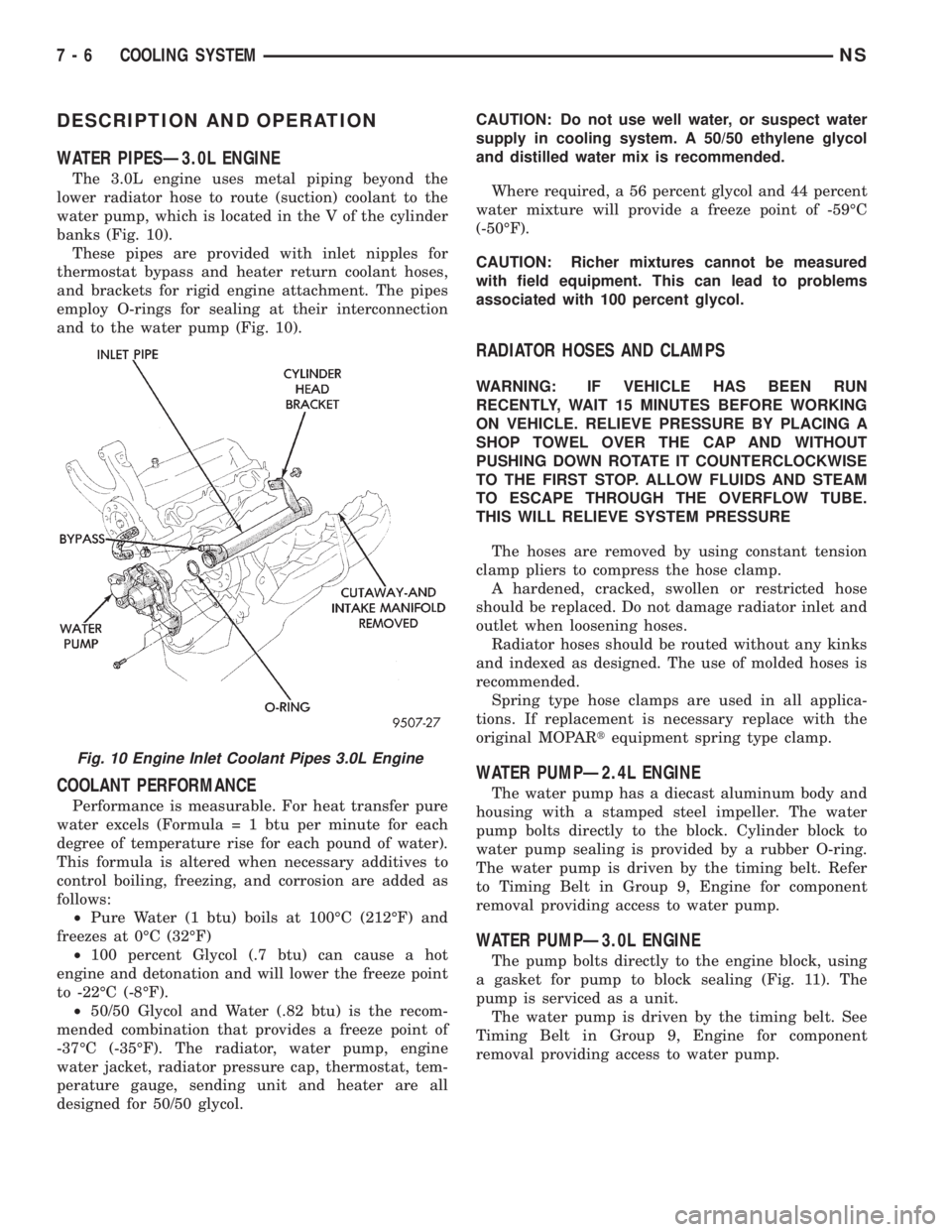
WATER PIPESÐ3.0L ENGINE
The 3.0L engine uses metal piping beyond the
lower radiator hose to route (suction) coolant to the
water pump, which is located in the V of the cylinder
banks (Fig. 10).
These pipes are provided with inlet nipples for
thermostat bypass and heater return coolant hoses,
and brackets for rigid engine attachment. The pipes
employ O-rings for sealing at their interconnection
and to the water pump (Fig. 10).
COOLANT PERFORMANCE
Performance is measurable. For heat transfer pure
water excels (Formula = 1 btu per minute for each
degree of temperature rise for each pound of water).
This formula is altered when necessary additives to
control boiling, freezing, and corrosion are added as
follows:
²Pure Water (1 btu) boils at 100ÉC (212ÉF) and
freezes at 0ÉC (32ÉF)
²100 percent Glycol (.7 btu) can cause a hot
engine and detonation and will lower the freeze point
to -22ÉC (-8ÉF).
²50/50 Glycol and Water (.82 btu) is the recom-
mended combination that provides a freeze point of
-37ÉC (-35ÉF). The radiator, water pump, engine
water jacket, radiator pressure cap, thermostat, tem-
perature gauge, sending unit and heater are all
designed for 50/50 glycol.CAUTION: Do not use well water, or suspect water
supply in cooling system. A 50/50 ethylene glycol
and distilled water mix is recommended.
Where required, a 56 percent glycol and 44 percent
water mixture will provide a freeze point of -59ÉC
(-50ÉF).
CAUTION: Richer mixtures cannot be measured
with field equipment. This can lead to problems
associated with 100 percent glycol.
RADIATOR HOSES AND CLAMPS
WARNING: IF VEHICLE HAS BEEN RUN
RECENTLY, WAIT 15 MINUTES BEFORE WORKING
ON VEHICLE. RELIEVE PRESSURE BY PLACING A
SHOP TOWEL OVER THE CAP AND WITHOUT
PUSHING DOWN ROTATE IT COUNTERCLOCKWISE
TO THE FIRST STOP. ALLOW FLUIDS AND STEAM
TO ESCAPE THROUGH THE OVERFLOW TUBE.
THIS WILL RELIEVE SYSTEM PRESSURE
The hoses are removed by using constant tension
clamp pliers to compress the hose clamp.
A hardened, cracked, swollen or restricted hose
should be replaced. Do not damage radiator inlet and
outlet when loosening hoses.
Radiator hoses should be routed without any kinks
and indexed as designed. The use of molded hoses is
recommended.
Spring type hose clamps are used in all applica-
tions. If replacement is necessary replace with the
original MOPARtequipment spring type clamp.
WATER PUMPÐ2.4L ENGINE
The water pump has a diecast aluminum body and
housing with a stamped steel impeller. The water
pump bolts directly to the block. Cylinder block to
water pump sealing is provided by a rubber O-ring.
The water pump is driven by the timing belt. Refer
to Timing Belt in Group 9, Engine for component
removal providing access to water pump.
WATER PUMPÐ3.0L ENGINE
The pump bolts directly to the engine block, using
a gasket for pump to block sealing (Fig. 11). The
pump is serviced as a unit.
The water pump is driven by the timing belt. See
Timing Belt in Group 9, Engine for component
removal providing access to water pump.
Fig. 10 Engine Inlet Coolant Pipes 3.0L Engine
7 - 6 COOLING SYSTEMNS
Page 229 of 1938
WARNING: WITH TOOL IN PLACE, PRESSURE
WILL BUILD UP FAST. EXCESSIVE PRESSURE
BUILT UP, BY CONTINUOUS ENGINE OPERATION,
MUST BE RELEASED TO A SAFE PRESSURE
POINT. NEVER PERMIT PRESSURE TO EXCEED 138
kPa (20 psi).
If the needle on the dial does not fluctuate, race
the engine a few times. If an abnormal amount of
coolant or steam emits from the tail pipe, it may
indicate a coolant leak caused by a faulty head gas-
ket, cracked engine block, or cracked cylinder head.
There may be internal leaks that can be deter-
mined by removing the oil dipstick. If water globules
appear intermixed with the oil it will indicate an
internal leak in the engine. If there is an internal
leak, the engine must be disassembled for repair.
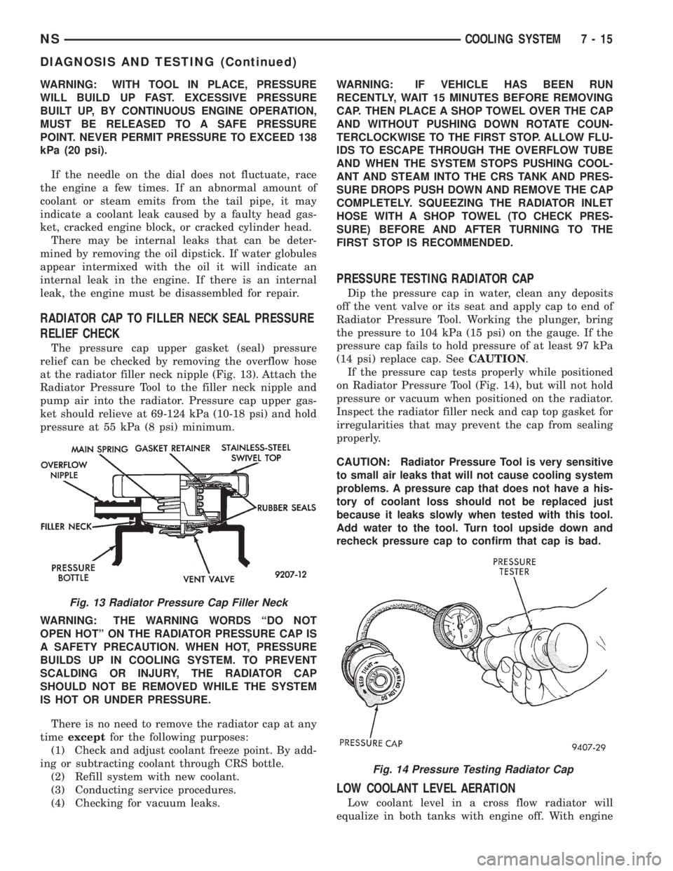
RADIATOR CAP TO FILLER NECK SEAL PRESSURE
RELIEF CHECK
The pressure cap upper gasket (seal) pressure
relief can be checked by removing the overflow hose
at the radiator filler neck nipple (Fig. 13). Attach the
Radiator Pressure Tool to the filler neck nipple and
pump air into the radiator. Pressure cap upper gas-
ket should relieve at 69-124 kPa (10-18 psi) and hold
pressure at 55 kPa (8 psi) minimum.
WARNING: THE WARNING WORDS ªDO NOT
OPEN HOTº ON THE RADIATOR PRESSURE CAP IS
A SAFETY PRECAUTION. WHEN HOT, PRESSURE
BUILDS UP IN COOLING SYSTEM. TO PREVENT
SCALDING OR INJURY, THE RADIATOR CAP
SHOULD NOT BE REMOVED WHILE THE SYSTEM
IS HOT OR UNDER PRESSURE.
There is no need to remove the radiator cap at any
timeexceptfor the following purposes:
(1) Check and adjust coolant freeze point. By add-
ing or subtracting coolant through CRS bottle.
(2) Refill system with new coolant.
(3) Conducting service procedures.
(4) Checking for vacuum leaks.WARNING: IF VEHICLE HAS BEEN RUN
RECENTLY, WAIT 15 MINUTES BEFORE REMOVING
CAP. THEN PLACE A SHOP TOWEL OVER THE CAP
AND WITHOUT PUSHING DOWN ROTATE COUN-
TERCLOCKWISE TO THE FIRST STOP. ALLOW FLU-
IDS TO ESCAPE THROUGH THE OVERFLOW TUBE
AND WHEN THE SYSTEM STOPS PUSHING COOL-
ANT AND STEAM INTO THE CRS TANK AND PRES-
SURE DROPS PUSH DOWN AND REMOVE THE CAP
COMPLETELY. SQUEEZING THE RADIATOR INLET
HOSE WITH A SHOP TOWEL (TO CHECK PRES-
SURE) BEFORE AND AFTER TURNING TO THE
FIRST STOP IS RECOMMENDED.
PRESSURE TESTING RADIATOR CAP
Dip the pressure cap in water, clean any deposits
off the vent valve or its seat and apply cap to end of
Radiator Pressure Tool. Working the plunger, bring
the pressure to 104 kPa (15 psi) on the gauge. If the
pressure cap fails to hold pressure of at least 97 kPa
(14 psi) replace cap. SeeCAUTION.
If the pressure cap tests properly while positioned
on Radiator Pressure Tool (Fig. 14), but will not hold
pressure or vacuum when positioned on the radiator.
Inspect the radiator filler neck and cap top gasket for
irregularities that may prevent the cap from sealing
properly.
CAUTION: Radiator Pressure Tool is very sensitive
to small air leaks that will not cause cooling system
problems. A pressure cap that does not have a his-
tory of coolant loss should not be replaced just
because it leaks slowly when tested with this tool.
Add water to the tool. Turn tool upside down and
recheck pressure cap to confirm that cap is bad.
LOW COOLANT LEVEL AERATION
Low coolant level in a cross flow radiator will
equalize in both tanks with engine off. With engine
Fig. 13 Radiator Pressure Cap Filler Neck
Fig. 14 Pressure Testing Radiator Cap
NSCOOLING SYSTEM 7 - 15
DIAGNOSIS AND TESTING (Continued)
Page 235 of 1938
INSTALLATION
(1) Place a new gasket (dipped in water) on the
thermostat housing surface, center thermostat into
opening in the intake manifold water box.
(2) Place housing and gasket over the thermostat,
making sure thermostat is in the recess provided
(Fig. 28).
(3) Bolt housing to intake manifold, tighten bolts
to 28 N´m (250 in. lbs.).
(4) Refill the cooling system to the proper level.
Refer to Cooling System Refilling outlined in this sec-
tion for procedure.
RADIATOR
REMOVAL
(1) Disconnect negative cable from battery.
WARNING: DO NOT REMOVE THE CYLINDER
BLOCK PLUG OR THE RADIATOR DRAINCOCK
WITH THE SYSTEM HOT AND UNDER PRESSURE
BECAUSE SERIOUS BURNS FROM COOLANT CAN
OCCUR.
(2) Drain cooling system. Refer to Draining Cool-
ing System of this section.
(3) Remove air intake resonator.
(4) Remove coolant reserve system tank to filler
neck tube hose.
(5) Disconnect fans from the connector located on
the left side of the fan module.
(6) Remove the Coolant Recovery System (CRS)
tank retaining screw from the upper radiator closure
panel crossmember.
(7) Disconnect the upper radiator mounting
screws from the crossmember. Disconnect the engine
block heater wire if equipped.
(8) Remove the upper radiator closure panel
crossmember. Refer to Group 23 Body for procedure.
(9) Remove air cleaner assembly.
(10) Disconnect automatic transmission oil cooler
lines at radiator and plug.
(11) Disconnect inlet and outlet hoses from the
radiator. Remove the lower hose clip from the fan
module.
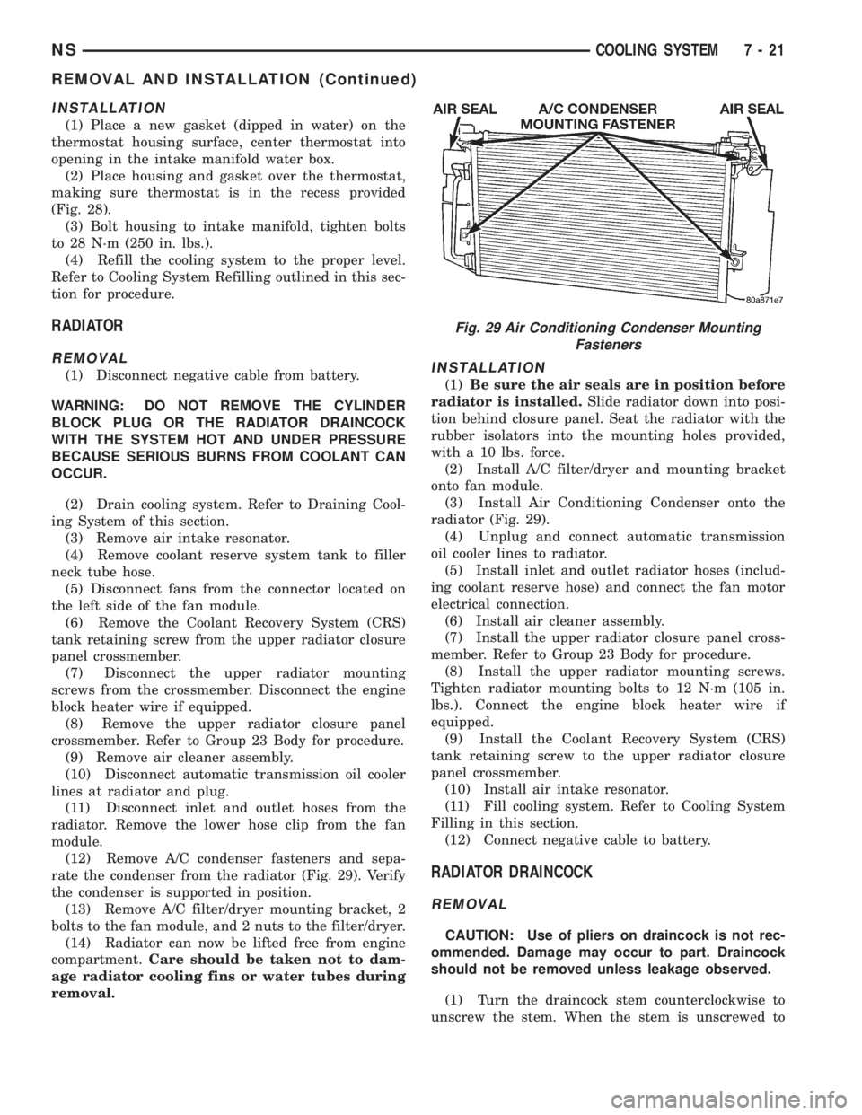
(12) Remove A/C condenser fasteners and sepa-
rate the condenser from the radiator (Fig. 29). Verify
the condenser is supported in position.
(13) Remove A/C filter/dryer mounting bracket, 2
bolts to the fan module, and 2 nuts to the filter/dryer.
(14) Radiator can now be lifted free from engine
compartment.Care should be taken not to dam-
age radiator cooling fins or water tubes during
removal.INSTALLATION
(1)Be sure the air seals are in position before
radiator is installed.Slide radiator down into posi-
tion behind closure panel. Seat the radiator with the
rubber isolators into the mounting holes provided,
with a 10 lbs. force.
(2) Install A/C filter/dryer and mounting bracket
onto fan module.
(3) Install Air Conditioning Condenser onto the
radiator (Fig. 29).
(4) Unplug and connect automatic transmission
oil cooler lines to radiator.
(5) Install inlet and outlet radiator hoses (includ-
ing coolant reserve hose) and connect the fan motor
electrical connection.
(6) Install air cleaner assembly.
(7) Install the upper radiator closure panel cross-
member. Refer to Group 23 Body for procedure.
(8) Install the upper radiator mounting screws.
Tighten radiator mounting bolts to 12 N´m (105 in.
lbs.). Connect the engine block heater wire if
equipped.
(9) Install the Coolant Recovery System (CRS)
tank retaining screw to the upper radiator closure
panel crossmember.
(10) Install air intake resonator.
(11) Fill cooling system. Refer to Cooling System
Filling in this section.
(12) Connect negative cable to battery.
RADIATOR DRAINCOCK
REMOVAL
CAUTION: Use of pliers on draincock is not rec-
ommended. Damage may occur to part. Draincock
should not be removed unless leakage observed.
(1) Turn the draincock stem counterclockwise to
unscrew the stem. When the stem is unscrewed to
Fig. 29 Air Conditioning Condenser Mounting
Fasteners
NSCOOLING SYSTEM 7 - 21
REMOVAL AND INSTALLATION (Continued)
Page 236 of 1938
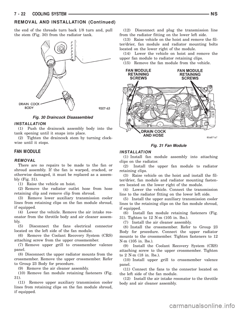
the end of the threads turn back 1/8 turn and, pull
the stem (Fig. 30) from the radiator tank.
INSTALLATION
(1) Push the draincock assembly body into the
tank opening until it snaps into place.
(2) Tighten the draincock stem by turning clock-
wise until it stops.
FAN MODULE
REMOVAL
There are no repairs to be made to the fan or
shroud assembly. If the fan is warped, cracked, or
otherwise damaged, it must be replaced as a assem-
bly (Fig. 31).
(1) Raise the vehicle on hoist.
(2) Remove the radiator outlet hose from hose
retaining clip and remove clip from shroud.
(3) Remove lower auxiliary transmission cooler
lines from retaining clips on the fan module shroud,
if equipped.
(4) Lower the vehicle. Remove the air intake res-
onator from the throttle body and air cleaner assem-
bly.
(5) Disconnect the fans electrical connector
located on the left side of the fan module.
(6) Remove the Coolant Recovery System (CRS)
attaching screw from the upper crossmember.
(7) Remove upper grill to crossmember valence
panel.
(8) Disconnect the upper radiator mounts from the
crossmember. Remove the upper crossmember. Refer
to Group 23 Body for procedure.
(9) Remove the air cleaner assembly.
(10) Remove fan module retaining fasteners (Fig.
31).
(11) Remove upper auxiliary transmission cooler
lines from retaining clips on the fan module shroud,
if equipped.(12) Disconnect and plug the transmission line
from the radiator fitting on the lower left side.
(13) Raise vehicle on the hoist and remove the fil-
ter/drier, fan module and radiator mounting bolts
located on the lower right of the module.
(14) Lower the vehicle on hoist and remove the
upper fan module to radiator retaining clips.
(15) Remove the fan module from the vehicle.
INSTALLATION
(1) Install fan module assembly into attaching
clips on the radiator.
(2) Install the upper fan module to radiator
retaining clips.
(3) Raise vehicle on the hoist and install the fil-
ter/drier, fan module and radiator mounting fasten-
ers located on the lower right of the module.
(4) Lower the vehicle. Connect the transmission
line to the radiator fitting on the lower left side.
(5) Install the upper auxiliary transmission cooler
lines to the retaining clips on the fan module shroud,
if equipped.
(6) Install fan module retaining fasteners (Fig.
31). Tighten to 12 N´m (105 in. lbs.).
(7) Install the air cleaner assembly.
(8) Install the crossmember. Refer to Group 23
Body for procedure. Connect the upper radiator
mounts to the crossmember. Tighten fasteners to 12
N´m (105 in. lbs.).
(9) Install the Coolant Recovery System (CRS)
attaching screw to the upper crossmember. Tighten
to 2 N´m (18 in. lbs.).
(10) Install upper grill to crossmember valence
panel.
(11) Connect the fans to the connector located on
the left side of the fan module.
(12) Install the air intake resonator to the throttle
body and air cleaner assembly.
Fig. 30 Draincock Disassembled
Fig. 31 Fan Module
7 - 22 COOLING SYSTEMNS
REMOVAL AND INSTALLATION (Continued)
Page 238 of 1938
ACCESSORY DRIVE BELTSÐ3.0L
GENERATOR/POWER STEERING PUMP BELT
REMOVAL/INSTALLATION
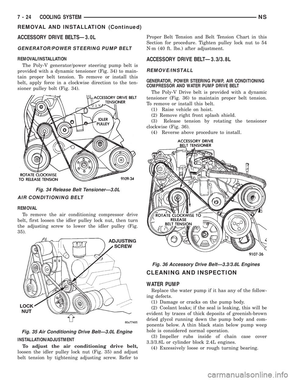
The Poly-V generator/power steering pump belt is
provided with a dynamic tensioner (Fig. 34) to main-
tain proper belt tension. To remove or install this
belt, apply force in a clockwise direction to the ten-
sioner pulley bolt (Fig. 34).
AIR CONDITIONING BELT
REMOVAL
To remove the air conditioning compressor drive
belt, first loosen the idler pulley lock nut, then turn
the adjusting screw to lower the idler pulley (Fig.
35).
INSTALLATION/ADJUSTMENT
To adjust the air conditioning drive belt,
loosen the idler pulley lock nut (Fig. 35) and adjust
belt tension by tightening adjusting screw. Refer toProper Belt Tension and Belt Tension Chart in this
Section for procedure. Tighten pulley lock nut to 54
N´m (40 ft. lbs.) after adjustment.
ACCESSORY DRIVE BELTÐ3.3/3.8L
REMOVE/INSTALL
GENERATOR, POWER STEERING PUMP, AIR CONDITIONING
COMPRESSOR AND WATER PUMP DRIVE BELT
The Poly-V Drive belt is provided with a dynamic
tensioner (Fig. 36) to maintain proper belt tension.
To remove or install this belt.
(1) Raise vehicle on hoist.
(2) Remove right front splash shield.
(3) Release tension by rotating the tensioner
clockwise (Fig. 36).
(4) Reverse above procedure to install.
CLEANING AND INSPECTION
WATER PUMP
Replace the water pump if it has any of the follow-
ing defects.
(1) Damage or cracks on the pump body.
(2) Coolant leaks; if the seal is leaking, this will be
evident by traces of thick deposits of greenish-brown
dried glycol running down the pump body and com-
ponents below. A thin black stain below pump weep
hole is considered normal operation.
(3) Impeller rubs inside of chain case cover
3.3/3.8L or cylinder block 2.4L engines.
(4) Excessively loose or rough turning bearing.
Fig. 34 Release Belt TensionerÐ3.0L
Fig. 35 Air Conditioning Drive BeltÐ3.0L Engine
Fig. 36 Accessory Drive BeltÐ3.3/3.8L Engines
7 - 24 COOLING SYSTEMNS
REMOVAL AND INSTALLATION (Continued)