turn signal CHRYSLER VOYAGER 1996 Service Manual
[x] Cancel search | Manufacturer: CHRYSLER, Model Year: 1996, Model line: VOYAGER, Model: CHRYSLER VOYAGER 1996Pages: 1938, PDF Size: 55.84 MB
Page 1548 of 1938
TORQUE MANAGEMENT
Most 41TE transaxles utilize torque management.
Torque management is a unique function of the Pow-
ertrain Control Module (PCM). The PCM receives
output signals from the Transmission Control Module
(TCM) and many various engine sensors. The PCM
evaluates these signals and decides if it is necessary
to decrease the output of the engine's torque. This
reduction in torque does not interfere with the nor-
mal operation of the vehicle. This reduction in torque
will prolong the life of the drivetrain components.
Torque reduction is not noticeable in normal driving
functions. The torque reduction function shuts off
above 16 MPH.
ON-BOARD DIAGNOSTICS
This vehicle utilizes a diagnostic system called
OBDII. The powertrain control module communicates
with the Transmission Control Module. Whenever
the transaxle sets a fault in the Transmission Con-
trol Module (dependent on which fault is set), the
powertrain control module will turn on a MIL (Mal-
function Indicator Lamp) on the instrument cluster.
By reading the code in the powertrain control module
it will tell you where the fault occurred. If the fault
occurred in the transaxle, the controller will read a
CODE 45.For further information regarding OBDII,
refer to Group 25, Emission Systems.
These controls provide comprehensive, on-board
transaxle diagnostics. The information available can
aid in transaxle diagnosis. For example, apply ele-
ment buildup rate indicates solenoid performance.
Also included are self diagnostic functions. Self diag-
nostics allow the technician to test the condition of
the electronic controls. The Transmission Control
Module continuously monitors its critical functions. It
also records any malfunctions, and the number of
engine starts since the last malfunction. This allows
the technician to use the information in the event of
a customer complaint.
TRANSMISSION CONTROL MODULE
Do not interchange Transmission Control Modules
with previous year transmission control modules. If a
same year TCM is being used from a different vehi-
cle, the following procedures must be performed:
²Quick Learn Procedure
²Electronic Pinion Factor Procedure
The Transmission Control Module is located on the
right inner fender panel, in the engine compartment.
It is held in place by four mounting screws.NOTE: If the Transmission Control Module has
been replaced, the following procedures must be
performed:
²Quick Learn Procedure: This procedure will
allow the transmission control module to learn the
characteristics of the vehicle.
²Electronic Pinion Factor Procedure: This proce-
dure will reprogram the TCM to compensate for dif-
ferent tire sizes and final drive ratios.
GEARSHIFT AND PARKING LOCK CONTROLS
The transaxle is controlled by a lever type gear-
shift incorporated within the steering column. The
control has six selector lever positions: P (park), R
(reverse), N (neutral), and D (drive), 2 (second), and
1 (first). The parking lock is applied by moving the
selector lever past a gate to the P position.Do not
apply the parking lock until the vehicle has
stopped; otherwise, a severe ratchet noise will
occur.
TRANSMISSION RANGE SENSOR
The 41TE transaxle is equipped with a transmis-
sion range sensor that is located on top of the valve
body. This sensor will allow for accurate transmission
gear position measurement.
To service the transmission range sensor (TRS),
you must remove the valve body. For repair proce-
dures, refer to the Removal and Installation section
within this group.
Also located within the TRS is a transmission tem-
perature sensor. This sensor is used to measure the
transmission fluid sump temperature. The transmis-
sion temperature sensor is serviced with the TRS as
a unit.
SHIFT POSITION INDICATOR
The shifter position indicator is located in the
instrument cluster. The shifter position indicator out-
lines with a box the gear position the transaxle man-
ual valve lever is in.
The transmission range sensor (located on the
valvebody) sends a signal to the TCM on the position
of the transaxle manual valve lever. The TCM
receives the switch signal and processes the data.
The TCM sends the Shift Lever Position (SLP) infor-
mation to the BCM via the CCD bus. The BCM then
outlines with a box the appropriate shifter position
indicator in the instrument cluster.
To replace the shifter position indicator, refer to
Group 8E, Instrument Panel And Gauges.
21 - 74 TRANSAXLE AND POWER TRANSFER UNITNS
DESCRIPTION AND OPERATION (Continued)
Page 1552 of 1938

REVERSE CLUTCH
Apply air pressure to the reverse clutch apply pas-
sage and watch for the push/pull piston to move rear-
ward. The piston should return to its starting
position when the air pressure is removed.
2/4 CLUTCH
Apply air pressure to the feed hole located on the
2/4 clutch retainer. Look in the area where the 2/4
piston contacts the first separator plate and watch
carefully for the 2/4 piston to move rearward. The
piston should return to its original position after the
air pressure is removed.
LOW/REVERSE CLUTCH
Apply air pressure to the low/reverse clutch feed
hole (rear of case, between 2 bolt holes). Then, look
in the area where the low/reverse piston contacts thefirst separator plate. Watch carefully for the piston to
move forward. The piston should return to its origi-
nal position after the air pressure is removed.
UNDERDRIVE CLUTCH
Because this clutch piston cannot be seen, its oper-
ation is checked by function. Air pressure is applied
to the low/reverse and the 2/4 clutches. This locks the
output shaft. Use a piece of rubber hose wrapped
around the input shaft and a pair of clamp-on pliers
to turn the input shaft. Next apply air pressure to
the underdrive clutch. The input shaft should not
rotate with hand torque. Release the air pressure
and confirm that the input shaft will rotate.
FLUID LEAKAGE-TORQUE CONVERTER HOUSING
AREA
(1) Check for source of leakage.
(2) Fluid leakage at or around the torque converter
area may originate from an engine oil leak. The area
should be examined closely. Factory fill fluid is red
and, therefore, can be distinguished from engine oil.
(3) Prior to removing the transaxle, perform the
following checks:
(4) When leakage is determined to originate from
the transaxle, check fluid level prior to removal of
the transaxle and torque converter.
(5) High oil level can result in oil leakage out the
vent in the manual shaft. If the fluid level is high,
adjust to proper level.
(6) After performing this operation, inspect for
leakage. If a leak persists, perform the following
operation on the vehicle. This will determine if the
torque converter or transaxle is leaking.
TORQUE CONVERTER LEAKAGE
Possible sources of torque converter leakage are:
²Torque converter weld leaks at the outside
(peripheral) weld.
²Torque converter hub weld.
NOTE: Hub weld is inside and not visible. Do not
attempt to repair. Replace torque converter.
SHIFT POSITION INDICATOR
The transmission range sensor (on the valve body)
sends a signal to the TCM on the position of the
transaxle manual valve lever. The TCM receives the
switch signal and processes the data. The TCM sends
the Shift Lever Position (SLP) information to the
BCM via the CCD bus. The BCM then outlines with
a box the appropriate shifter position indicator in the
instrument cluster.
Fig. 3 Air Pressure Test Plate
Fig. 4 Testing Reverse Clutch
21 - 78 TRANSAXLE AND POWER TRANSFER UNITNS
DIAGNOSIS AND TESTING (Continued)
Page 1824 of 1938
COOLDOWN TEST ENTRY
TO INITIATE TESTS:
²Set Blower motor ON HIGH
²Set Mode position to Panel
²Open all A/C outlets
²Set Temperature to Cold (Both slide pots if
equipped)
²Depress WASH and A/C simultaneously for 5
Seconds
NOTE: Prior to start of test, If the evaporator is
already cold, the system will fail test. To correct,
operate system with A/C OFF and the blower motor
ON high for three minutes prior to starting test.
RESULTS:
²All LED's will turn on for 5 Seconds
²Cooldown Test is running when A/C and
RECIRC. are alternately flashing. If A/C and
RECIRC. are flashing simultaneously, Cooldown has
failed.
CALIBRATION DIAGNOSTICS AND
COOLDOWN ABORT
Test can be aborted by doing one of the following:
²Depressing Rear Window Defogger, RECIRC and
Rear Wiper buttons.
²Cycling Ignition OFF and then ON.
²Control will automatically abort after 15 min-
utes from the time Calibration Diagnostics and
Cooldown was entered.
The HVAC control module will return to normal
operation or may indicate unsuccessful Calibration
Diagnostics or Cooldown test by LED's flashing
simultaneously.
EEPROM DATA
Calibration Diagnostics, Cooldown Status and
evaporator temperature Fin Sensor values are stored
in an EEPROM memory internal to the control. The
microcomputer within the HVAC control module uses
this information:
²To determine if Cooldown needs to run
²For proper position of the Heater-A/C unit
assembly doors
ACTUATOR CALIBRATION AND
DIAGNOSTICS.
NOTE: Do not run actuators unless they are prop-
erly mounted on the HVAC control module.
Actuator end point calibration takes approximately
60 seconds. The REAR WIPER and INTERMITTENT
LED's will flash alternately during the test. The con-
trol will cycle the Blend actuator(s) to the Heat stopfirst then back to Cold. After the Blend actuator(s)
have been calibrated the Mode actuator will be cycled
to Defrost and then to Panel. Successful calibration
is defined as actuator travel falling within their min-
imum and maximum limits.
BLEND/PASSENGER ACTUATOR BACKGROUND
The Blend/Passenger Actuator can move the tem-
perature door in two directions. When the voltage at
Pin 12 of the control module is high, about 11.5 volts,
and the voltage at Pin 17 is low, about 1.5 volts, the
door will move towards the Heat position. When Pin
17 is High and Pin 12 is Low the door will move
towards the Cold position. When both Pins are high
or both Pins are low, the actuator will not move. The
Blend/Passenger feedback signal is a voltage signal
that is supplied by the actuator to the control. The
signal will be about 4.0 volts in the Heat position
and 1.0 volt in the Cold position. As the position of
the Blend/Passenger actuator changes, so will the
feedback signal. The feedback signal is necessary for
the correct positioning of the temperature door.
DRIVER ACTUATOR BACKGROUND
The Driver Actuator can move the temperature
door in two directions. When the voltage at Pin 15 of
the control module is high, about 11.5 volts, and the
voltage at Pin 13 is low, about 1.5 volts the door will
move towards the Cold position. When Pin 13 is High
and Pin 15 is Low the door will move towards the
Heat position. When both Pins are high or when both
Pins are low, the actuator will not move. The Driver
feedback signal is a voltage signal that is supplied by
the actuator to the control. The signal will be about
4.0 volts in the Heat position and 1.0 volt in the Cold
position. As the position of the Driver Actuator
changes, so will the feedback signal. The feedback
signal is necessary for the correct positioning of the
temperature door.
MODE ACTUATOR BACKGROUND
The Mode actuator can move the mode door in two
directions. When the voltage at Pin 18 of the control
module is high, about 11.5 volts, and the voltage at
Pin 12 is low, about 1.5 volts the door will move
towards the Panel position. When Pin 12 is High and
Pin 18 is Low the door will move towards the Defrost
position. When both Pin are high or when both Pins
are low, the actuator will not move. The Mode door
feedback signal is a voltage signal that is supplied by
the actuator to the control. The signal will be about
4.5 volts in the Panel position and 0.5 volts in the
Defrost position. As the position of the Mode actuator
changes, so will the feedback signal. The feedback
signal is necessary for the correct positioning of the
mode door.
24 - 8 HEATING AND AIR CONDITIONINGNS
DIAGNOSIS AND TESTING (Continued)
Page 1873 of 1938
COOLDOWN TEST ENTRY
TO INITIATE TESTS:
²Set Blower motor ON HIGH
²Set Mode position to Panel
²Open all A/C outlets
²Set Temperature to Cold (Both slide pots if
equipped)
²Depress WASH and A/C simultaneously for 5
Seconds
NOTE: Prior to start of test, If the evaporator is
already cold, the system will fail test. To correct,
operate system with A/C OFF and the blower motor
ON high for three minutes prior to starting test.
RESULTS:
²All LED's will turn on for 5 Seconds
²Cooldown Test is running when A/C and
RECIRC. are alternately flashing. If A/C and
RECIRC. are flashing simultaneously, Cooldown has
failed.
CALIBRATION DIAGNOSTICS AND
COOLDOWN ABORT
Test can be aborted by doing one of the following:
²Depressing Rear Window Defogger, RECIRC and
Rear Wiper buttons.²Cycling Ignition OFF and then ON.
²Control will automatically abort after 15 min-
utes from the time Calibration Diagnostics and
Cooldown was entered.
The HVAC control module will return to normal
operation or may indicate unsuccessful Calibration
Diagnostics or Cooldown test by LED's flashing
simultaneously.
EEPROM DATA
Calibration Diagnostics, Cooldown Status and
evaporator temperature Fin Sensor values are stored
in an EEPROM memory internal to the control. The
microcomputer within the HVAC control module uses
this information:
²To determine if Cooldown needs to run
²For proper position of the Heater-A/C unit
assembly doors
ACTUATOR CALIBRATION AND
DIAGNOSTICS.
NOTE: Do not run actuators unless they are prop-
erly mounted on the HVAC control module.
Actuator end point calibration takes approximately
60 seconds. The REAR WIPER and INTERMITTENT
LED's will flash alternately during the test. The con-
trol will cycle the Blend actuator(s) to the Heat stop
first then back to Cold. After the Blend actuator(s)
have been calibrated the Mode actuator will be cycled
to Defrost and then to Panel. Successful calibration
is defined as actuator travel falling within their min-
imum and maximum limits.
BLEND/PASSENGER ACTUATOR BACKGROUND
The Blend/Passenger Actuator can move the tem-
perature door in two directions. When the voltage at
Pin 12 of the control module is high, about 11.5 volts,
and the voltage at Pin 17 is low, about 1.5 volts, the
door will move towards the Heat position. When Pin
17 is High and Pin 12 is Low the door will move
towards the Cold position. When both Pins are high
or both Pins are low, the actuator will not move. The
Blend/Passenger feedback signal is a voltage signal
that is supplied by the actuator to the control. The
signal will be about 4.0 volts in the Heat position
and 1.0 volt in the Cold position. As the position of
the Blend/Passenger actuator changes, so will the
feedback signal. The feedback signal is necessary for
the correct positioning of the temperature door.
DRIVER ACTUATOR BACKGROUND
The Driver Actuator can move the temperature
door in two directions. When the voltage at Pin 15 of
the control module is high, about 11.5 volts, and the
voltage at Pin 13 is low, about 1.5 volts the door will
LED'S PASS/FAILCORRECTIVE
ACTION
NO LED'S
FLASHING-
NORMAL
OPERATIONPASSED
CALIBRATION,
DIAGNOSTICS
AND
COOLDOWNNONE
REAR WIPER
AND
INTERMITTENT
LED'S FLASH
SIMULTANEOUSLYFAILED
CALIBRATION
DIAGNOSTICSRUN
CALIBRATION
TEST
A/C AND RECIRC
LED'S FLASH
SIMULTANEOUSLYFAILED
COOLDOWNRUN
COOLDOWN
TEST
REAR WIPER
AND
INTERMITTENT
LED'S ARE
FLASHING
SIMULTANEOUSLY
A/C AND RECIRC
LED'S ARE
FLASHING
SIMULTANEOUSLYFAILED
CALIBRATION,
DIAGNOSTICS
AND FAILED
COOLDOWN
TESTRUN
CALIBRATION
TEST
NS/GSHEATING AND AIR CONDITIONING 24 - 7
DIAGNOSIS AND TESTING (Continued)
Page 1915 of 1938
components now have input (rationality) and output
(functionality) checks. Previously, a component like
the Throttle Position sensor (TPS) was checked by
the PCM for an open or shorted circuit. If one of
these conditions occurred, a DTC was set. Now there
is a check to ensure that the component is working.
This is done by watching for a TPS indication of a
greater or lesser throttle opening than MAP and
engine rpm indicate. In the case of the TPS, if engine
vacuum is high and engine rpm is 1600 or greater
and the TPS indicates a large throttle opening, a
DTC will be set. The same applies to low vacuum
and 1600 rpm.
Any component that has an associated limp in will
set a fault after 1 trip with the malfunction present.
Refer to the Diagnostic Trouble Codes Description
Charts in this section and the appropriate Power-
train Diagnostic Procedure Manual for diagnostic
procedures.
NON-MONITORED CIRCUITS
The PCM does not monitor all circuits, systems
and conditions that could have malfunctions causing
driveability problems. However, problems with these
systems may cause the PCM to store diagnostic trou-
ble codes for other systems or components. For exam-
ple, a fuel pressure problem will not register a fault
directly, but could cause a rich/lean condition or mis-
fire. This could cause the PCM to store an oxygen
sensor or misfire diagnostic trouble code.
The major non-monitored circuits are listed below
along with examples of failures modes that do not
directly cause the PCM to set a DTC, but for a sys-
tem that is monitored.
FUEL PRESSURE
The fuel pressure regulator controls fuel system
pressure. The PCM cannot detect a clogged fuel
pump inlet filter, clogged in-line fuel filter, or a
pinched fuel supply or return line. However, these
could result in a rich or lean condition causing the
PCM to store an oxygen sensor or fuel system diag-
nostic trouble code.
SECONDARY IGNITION CIRCUIT
The PCM cannot detect an inoperative ignition coil,
fouled or worn spark plugs, ignition cross firing, or
open spark plug cables.
CYLINDER COMPRESSION
The PCM cannot detect uneven, low, or high engine
cylinder compression.
EXHAUST SYSTEM
The PCM cannot detect a plugged, restricted or
leaking exhaust system. It may set a EGR or Fuel
system fault or O2S.
FUEL INJECTOR MECHANICAL
MALFUNCTIONS
The PCM cannot determine if a fuel injector is
clogged, the needle is sticking or if the wrong injector
is installed. However, these could result in a rich or
lean condition causing the PCM to store a diagnostic
trouble code for either misfire, an oxygen sensor, or
the fuel system.
EXCESSIVE OIL CONSUMPTION
Although the PCM monitors engine exhaust oxygen
content when the system is in closed loop, it cannot
determine excessive oil consumption.
THROTTLE BODY AIR FLOW
The PCM cannot detect a clogged or restricted air
cleaner inlet or filter element.
VACUUM ASSIST
The PCM cannot detect leaks or restrictions in the
vacuum circuits of vacuum assisted engine control
system devices. However, these could cause the PCM
to store a MAP sensor diagnostic trouble code and
cause a high idle condition.
PCM SYSTEM GROUND
The PCM cannot determine a poor system ground.
However, one or more diagnostic trouble codes may
be generated as a result of this condition. The mod-
ule should be mounted to the body at all times, also
during diagnostic.
PCM CONNECTOR ENGAGEMENT
The PCM may not be able to determine spread or
damaged connector pins. However, it might store
diagnostic trouble codes as a result of spread connec-
tor pins.
HIGH AND LOW LIMITS
The PCM compares input signal voltages from each
input device with established high and low limits for
the device. If the input voltage is not within limits
and other criteria are met, the PCM stores a diagnos-
tic trouble code in memory. Other diagnostic trouble
code criteria might include engine RPM limits or
input voltages from other sensors or switches that
must be present before verifying a diagnostic trouble
code condition.
NSEMISSION CONTROL SYSTEMS 25 - 11
DESCRIPTION AND OPERATION (Continued)
Page 1923 of 1938
the amount of EGR supplied to the engine. This pro-
vides the correct amount of exhaust gas recirculation
for different operating conditions.
This system does not allow EGR at idle. The EGR
systems can operate at all coolant temperatures
above 60ÉF as long as the battery ambient tempera-
ture is above 7ÉF.
DIAGNOSIS AND TESTING
EGR SYSTEM ON-BOARD DIAGNOSTICS
The PCM performs an on-board diagnostic check of
the EGR system. The diagnostic system uses the
electronic EGR transducer for the system tests.
The diagnostic check activates only during selected
engine/driving conditions. When the conditions are
met, the PCM energizes the transducer solenoid to
disable the EGR. The PCM checks for a change in
the heated oxygen sensor signal. If the air-fuel mix-
ture goes lean, the PCM will attempt to enrichen the
mixture. The PCM registers a Diagnostic Trouble
Code (DTC) if the EGR system is not operating cor-
rectly. After registering a DTC, the PCM turns on the
malfunction indicator (Check Engine) lamp after 2
consecutive trips. There are 2 types of failures sensed
by the PCM. The first is a short or open in the elec-
trical solenoid circuit. The second is a mechanical
failure or loss of vacuum. The Malfunction Indicator
Lamp (MIL) indicates the need for service.
If a problem is indicated by the MIL and a DTC for
the EGR system is set, check for proper operation of
the EGR system. Use the System Test, EGR Gas
Flow Test. If the EGR system tests properly, check
the system using the DRB scan tool. Refer to
On-Board Diagnosis sections in this Group. Also,
refer to the DRB scan tool and the appropriate Pow-
ertrain Diagnostics Procedure manual.
EGR SYSTEM TEST
WARNING: APPLY PARKING BRAKE AND/OR
BLOCK WHEELS BEFORE TESTING THE EGR SYS-
TEM.
(1) Check the condition of all EGR system hoses
and tubes for leaks, cracks, kinks and hardening of
rubber hoses. Repair and correct these conditions
before performing any tests.
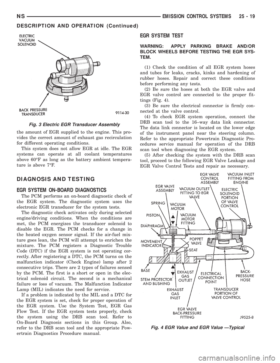
(2) Be sure the hoses at both the EGR valve and
EGR valve control are connected to the proper fit-
tings (Fig. 4).
(3) Be sure the electrical connector is firmly con-
nected at the valve control.
(4) To check EGR system operation, connect the
DRB scan tool to the 16±way data link connector.
The data link connector is located on the lower edge
of the instrument panel near the steering column.
Refer to the appropriate Powertrain Diagnostic Pro-
cedures service manual for operation of the DRB
scan tool when diagnosing the EGR system.
(5) After checking the system with the DRB scan
tool, proceed to the following EGR Valve Leakage and
EGR Valve Control Tests and repair as necessary.
Fig. 3 Electric EGR Transducer Assembly
Fig. 4 EGR Value and EGR Value ÐTypical
NSEMISSION CONTROL SYSTEMS 25 - 19
DESCRIPTION AND OPERATION (Continued)
Page 1929 of 1938
EMISSION CONTROL SYSTEM
CONTENTS
page page
EMISSION CONTROL SYSTEMÐ
2.0L ENGINE.......................... 9
EXHAUST EMISSION CONTROLSÐ
2.5L DIESEL ENGINE................... 5ON-BOARD DIAGNOSTICSÐ
2.5L DIESEL ENGINE................... 1
ON-BOARD DIAGNOSTICSÐ2.5L DIESEL ENGINE
INDEX
page page
GENERAL INFORMATION
SYSTEM DESCRIPTIONÐ
2.5L DIESEL ENGINE................... 1DESCRIPTION AND OPERATION
DIAGNOSTIC TROUBLE CODES............ 2
GENERAL INFORMATION
SYSTEM DESCRIPTIONÐ2.5L DIESEL ENGINE
The 2.5L diesel Powertrain Control Module (PCM)
monitors and controls many different circuits in the
fuel injection pump and engine systems. If the PCM
senses a problem with a monitored circuit that indi-
cates an actual problem, a Diagnostic Trouble Code
(DTC) will be stored in the PCM's memory, and even-
tually will illuminate the Diesel Glow Plug lamp con-
stantly while the key is on. If the problem is
repaired, or is intermittent, the PCM will erase the
DTC after 40 warm-up cycles. A warm-up cycle con-
sists of starting the vehicle when the engine is cold,
then the engine to warms up to a certain tempera-
ture, and finally, the engine temperature falls to a
normal operating temperature, then the key is
turned off.
Certain criteria must be met for a DTC to be
entered into PCM memory. The criteria may be a
specific range of engine rpm, engine or fuel tempera-
ture and/or input voltage to the PCM. A DTC indi-
cates that the PCM has identified an abnormal
signal in a circuit or the system. A DTC may indicate
the result of a failure, but never identify the failed
component directly.
There are several operating conditions that the
PCM does not monitor and set a DTC for. Refer to
the following Monitored Circuits and Non±Monitored
Circuits in this section.
MONITORED CIRCUITS
The PCM can detect certain problems in the elec-
trical system.
Open or Shorted Circuit± The PCM can deter-
mine if sensor output (which is the input to PCM) is
within proper range. It also determines if the circuit
is open or shorted.
Output Device Current Flow± The PCM senses
whether the output devices are electrically connected.
If there is a problem with the circuit, the PCM
senses whether the circuit is open, shorted to ground
(±), or shorted to (+) voltage.
NON±MONITORED CIRCUITS
The PCM does not monitor the following circuits,
systems or conditions that could have malfunctions
that result in driveability problems. A DTC will not
be displayed for these conditions.
Fuel Pressure:Fuel pressure is controlled by the
fuel injection pump. The PCM cannot detect prob-
lems in this component.
Cylinder Compression:The PCM cannot detect
uneven, low, or high engine cylinder compression.
Exhaust System:The PCM cannot detect a
plugged, restricted or leaking exhaust system.
Fuel Injector Malfunctions:The PCM cannot
determine if the fuel injector is clogged, or the wrong
injector is installed. The fuel injectors on the diesel
engine arenot controlledby the PCM, although a
NS/GSEMISSION CONTROL SYSTEM 25 - 1