CHRYSLER VOYAGER 1996 Service Manual
Manufacturer: CHRYSLER, Model Year: 1996, Model line: VOYAGER, Model: CHRYSLER VOYAGER 1996Pages: 1938, PDF Size: 55.84 MB
Page 1851 of 1938
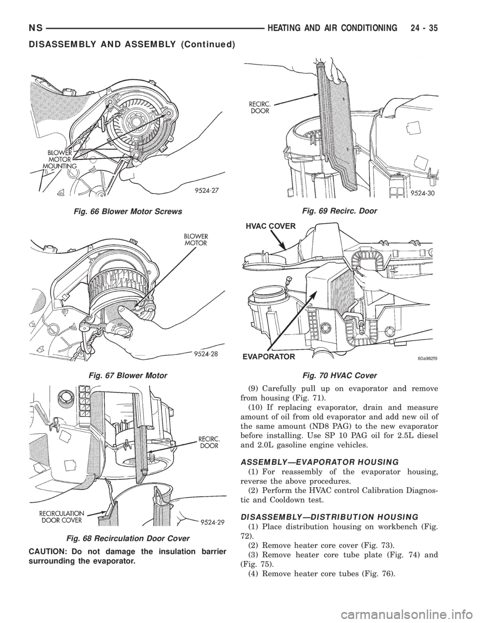
CAUTION: Do not damage the insulation barrier
surrounding the evaporator.(9) Carefully pull up on evaporator and remove
from housing (Fig. 71).
(10) If replacing evaporator, drain and measure
amount of oil from old evaporator and add new oil of
the same amount (ND8 PAG) to the new evaporator
before installing. Use SP 10 PAG oil for 2.5L diesel
and 2.0L gasoline engine vehicles.
ASSEMBLYÐEVAPORATOR HOUSING
(1) For reassembly of the evaporator housing,
reverse the above procedures.
(2) Perform the HVAC control Calibration Diagnos-
tic and Cooldown test.
DISASSEMBLYÐDISTRIBUTION HOUSING
(1) Place distribution housing on workbench (Fig.
72).
(2) Remove heater core cover (Fig. 73).
(3) Remove heater core tube plate (Fig. 74) and
(Fig. 75).
(4) Remove heater core tubes (Fig. 76).
Fig. 66 Blower Motor Screws
Fig. 67 Blower Motor
Fig. 68 Recirculation Door Cover
Fig. 69 Recirc. Door
Fig. 70 HVAC Cover
NSHEATING AND AIR CONDITIONING 24 - 35
DISASSEMBLY AND ASSEMBLY (Continued)
Page 1852 of 1938
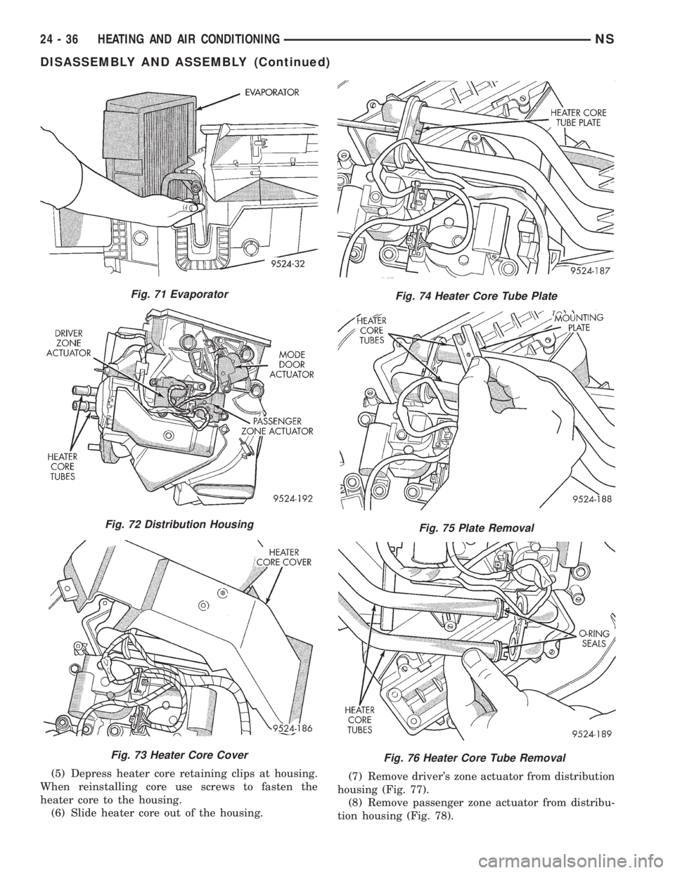
(5) Depress heater core retaining clips at housing.
When reinstalling core use screws to fasten the
heater core to the housing.
(6) Slide heater core out of the housing.(7) Remove driver's zone actuator from distribution
housing (Fig. 77).
(8) Remove passenger zone actuator from distribu-
tion housing (Fig. 78).
Fig. 71 Evaporator
Fig. 72 Distribution Housing
Fig. 73 Heater Core Cover
Fig. 74 Heater Core Tube Plate
Fig. 75 Plate Removal
Fig. 76 Heater Core Tube Removal
24 - 36 HEATING AND AIR CONDITIONINGNS
DISASSEMBLY AND ASSEMBLY (Continued)
Page 1853 of 1938
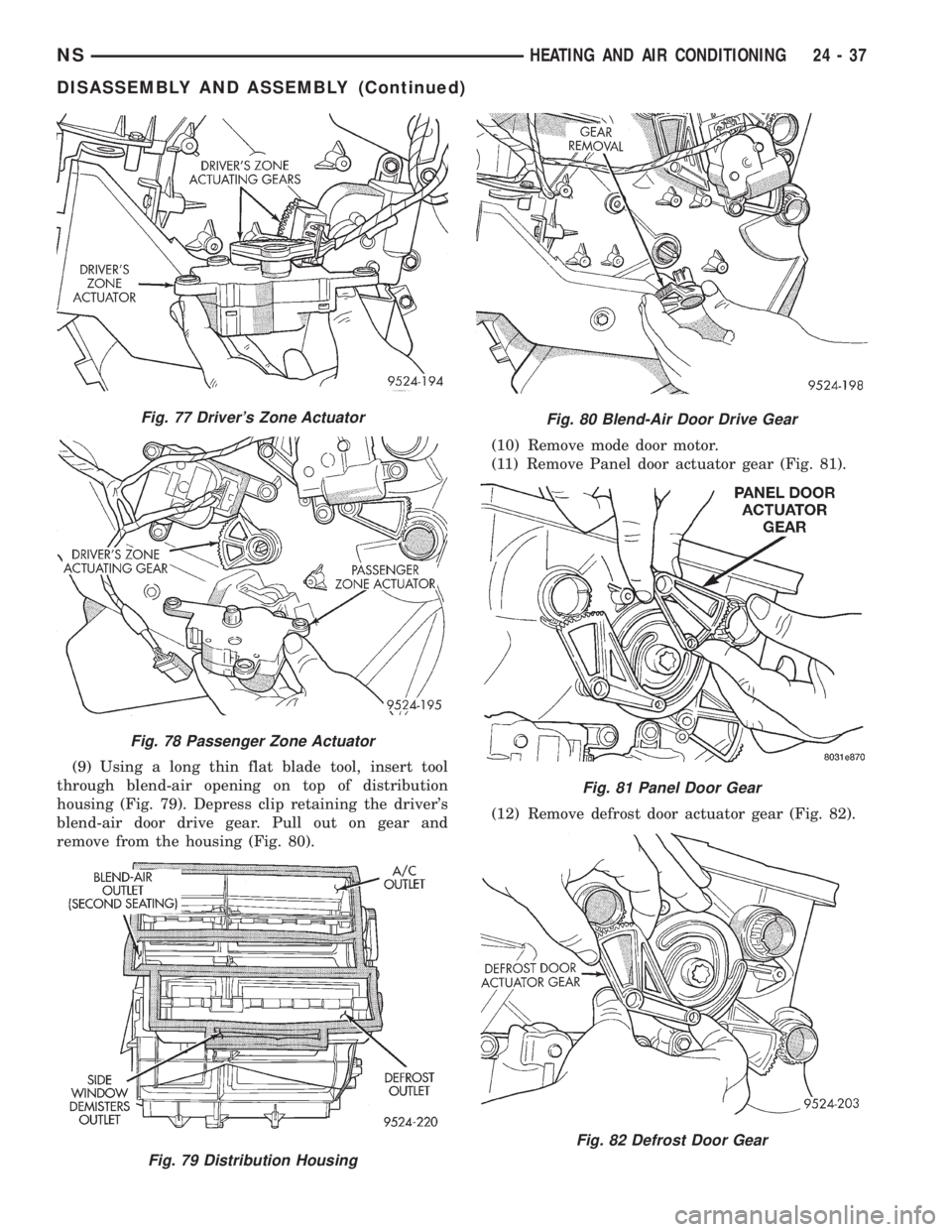
(9) Using a long thin flat blade tool, insert tool
through blend-air opening on top of distribution
housing (Fig. 79). Depress clip retaining the driver's
blend-air door drive gear. Pull out on gear and
remove from the housing (Fig. 80).(10) Remove mode door motor.
(11) Remove Panel door actuator gear (Fig. 81).
(12) Remove defrost door actuator gear (Fig. 82).
Fig. 77 Driver's Zone Actuator
Fig. 78 Passenger Zone Actuator
Fig. 79 Distribution Housing
Fig. 80 Blend-Air Door Drive Gear
Fig. 81 Panel Door Gear
Fig. 82 Defrost Door Gear
NSHEATING AND AIR CONDITIONING 24 - 37
DISASSEMBLY AND ASSEMBLY (Continued)
Page 1854 of 1938
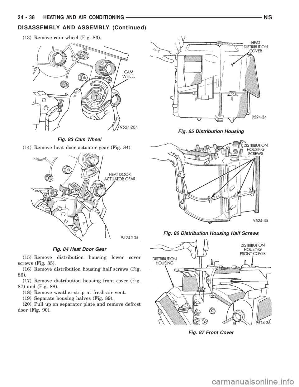
(13) Remove cam wheel (Fig. 83).
(14) Remove heat door actuator gear (Fig. 84).
(15) Remove distribution housing lower cover
screws (Fig. 85).
(16) Remove distribution housing half screws (Fig.
86).
(17) Remove distribution housing front cover (Fig.
87) and (Fig. 88).
(18) Remove weather-strip at fresh-air vent.
(19) Separate housing halves (Fig. 89).
(20) Pull up on separator plate and remove defrost
door (Fig. 90).
Fig. 83 Cam Wheel
Fig. 84 Heat Door Gear
Fig. 85 Distribution Housing
Fig. 86 Distribution Housing Half Screws
Fig. 87 Front Cover
24 - 38 HEATING AND AIR CONDITIONINGNS
DISASSEMBLY AND ASSEMBLY (Continued)
Page 1855 of 1938
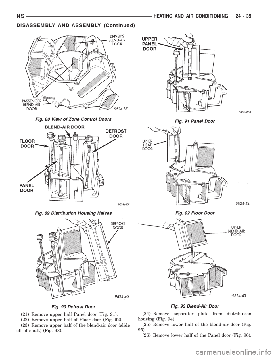
(21) Remove upper half Panel door (Fig. 91).
(22) Remove upper half of Floor door (Fig. 92).
(23) Remove upper half of the blend-air door (slide
off of shaft) (Fig. 93).(24) Remove separator plate from distribution
housing (Fig. 94).
(25) Remove lower half of the blend-air door (Fig.
95).
(26) Remove lower half of the Panel door (Fig. 96).
Fig. 88 View of Zone Control Doors
Fig. 89 Distribution Housing Halves
Fig. 90 Defrost Door
Fig. 91 Panel Door
Fig. 92 Floor Door
Fig. 93 Blend-Air Door
NSHEATING AND AIR CONDITIONING 24 - 39
DISASSEMBLY AND ASSEMBLY (Continued)
Page 1856 of 1938
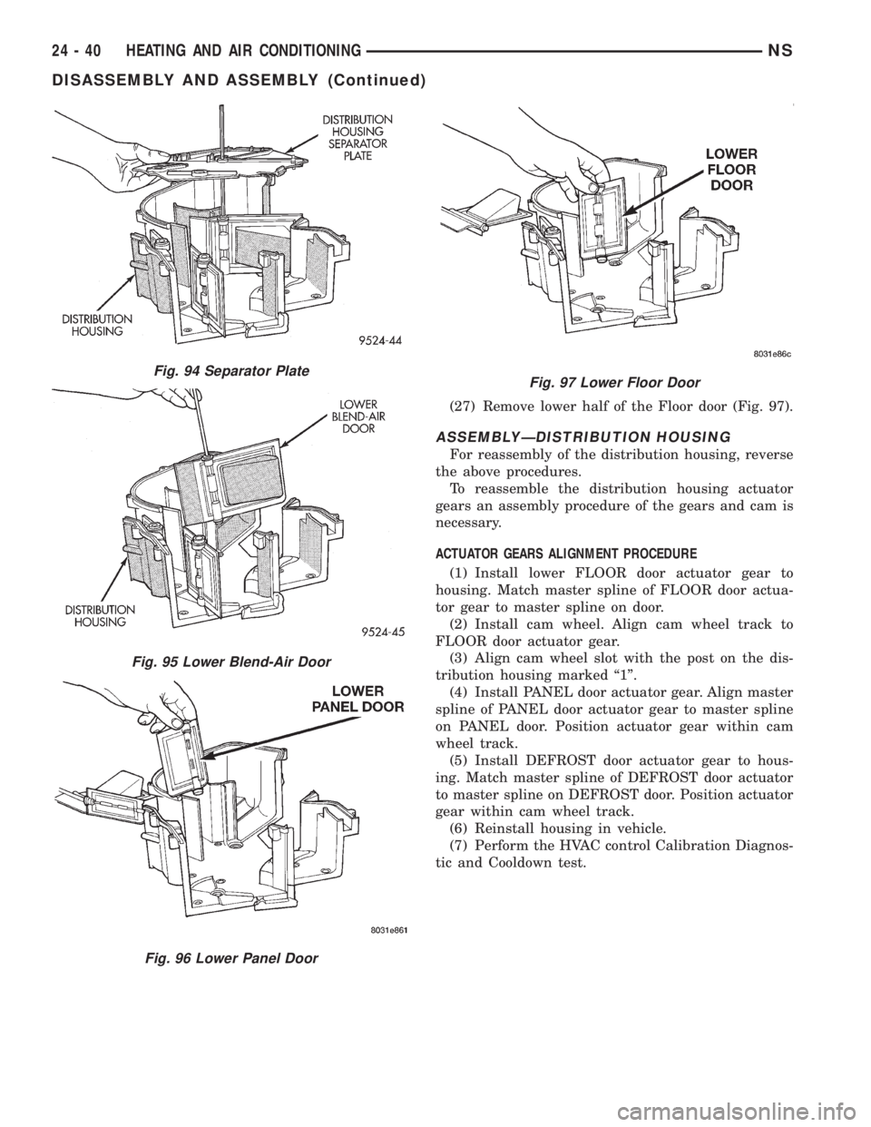
(27) Remove lower half of the Floor door (Fig. 97).
ASSEMBLYÐDISTRIBUTION HOUSING
For reassembly of the distribution housing, reverse
the above procedures.
To reassemble the distribution housing actuator
gears an assembly procedure of the gears and cam is
necessary.
ACTUATOR GEARS ALIGNMENT PROCEDURE
(1) Install lower FLOOR door actuator gear to
housing. Match master spline of FLOOR door actua-
tor gear to master spline on door.
(2) Install cam wheel. Align cam wheel track to
FLOOR door actuator gear.
(3) Align cam wheel slot with the post on the dis-
tribution housing marked ª1º.
(4) Install PANEL door actuator gear. Align master
spline of PANEL door actuator gear to master spline
on PANEL door. Position actuator gear within cam
wheel track.
(5) Install DEFROST door actuator gear to hous-
ing. Match master spline of DEFROST door actuator
to master spline on DEFROST door. Position actuator
gear within cam wheel track.
(6) Reinstall housing in vehicle.
(7) Perform the HVAC control Calibration Diagnos-
tic and Cooldown test.
Fig. 97 Lower Floor DoorFig. 94 Separator Plate
Fig. 95 Lower Blend-Air Door
Fig. 96 Lower Panel Door
24 - 40 HEATING AND AIR CONDITIONINGNS
DISASSEMBLY AND ASSEMBLY (Continued)
Page 1857 of 1938
REAR HEATING AND AIR CONDITIONING SYSTEM
INDEX
page page
GENERAL INFORMATION
INTRODUCTION......................... 41
DESCRIPTION AND OPERATION
REAR BLOWER RESISTOR BLOCK.......... 41
REAR HEATER AND A/C LINES............. 41
SYSTEM OPERATION.................... 41
DIAGNOSIS AND TESTING
DIAGNOSTIC PROCEDURES............... 43
REMOVAL AND INSTALLATION
AIR DISTRIBUTION DUCT-A/C.............. 43
AIR DISTRIBUTION DUCT-HEATER.......... 43
EVAPORATOR AND EXPANSION VALVE...... 44MODE DOOR ACTUATOR................. 49
MODE DOOR........................... 49
REAR AIR CONDITIONING LINES........... 45
REAR HEATER A/C AIR OUTLETS........... 45
REAR HEATER A/C BLOWER MOTOR........ 46
REAR HEATER A/C UNIT.................. 46
REAR HEATER CORE.................... 48
REAR HEATER LINES.................... 49
REAR HEATER-A/C AUXILIARY CONDENSER . . 45
REAR HEATER-A/C CONTROL ILLUMINATION
BULB............................... 46
GENERAL INFORMATION
INTRODUCTION
For proper operation of the rear heating A/C sys-
tem, refer to Owner's Manual supplied with the vehi-
cle.
DESCRIPTION AND OPERATION
REAR BLOWER RESISTOR BLOCK
The rear blower motor resistor is not serviceable
separately. The resistor is integral to the blower
motor. If resistor is faulty, it is necessary to replace
the complete blower motor.
REAR HEATER AND A/C LINES
The rear heater and A/C lines are all serviced as
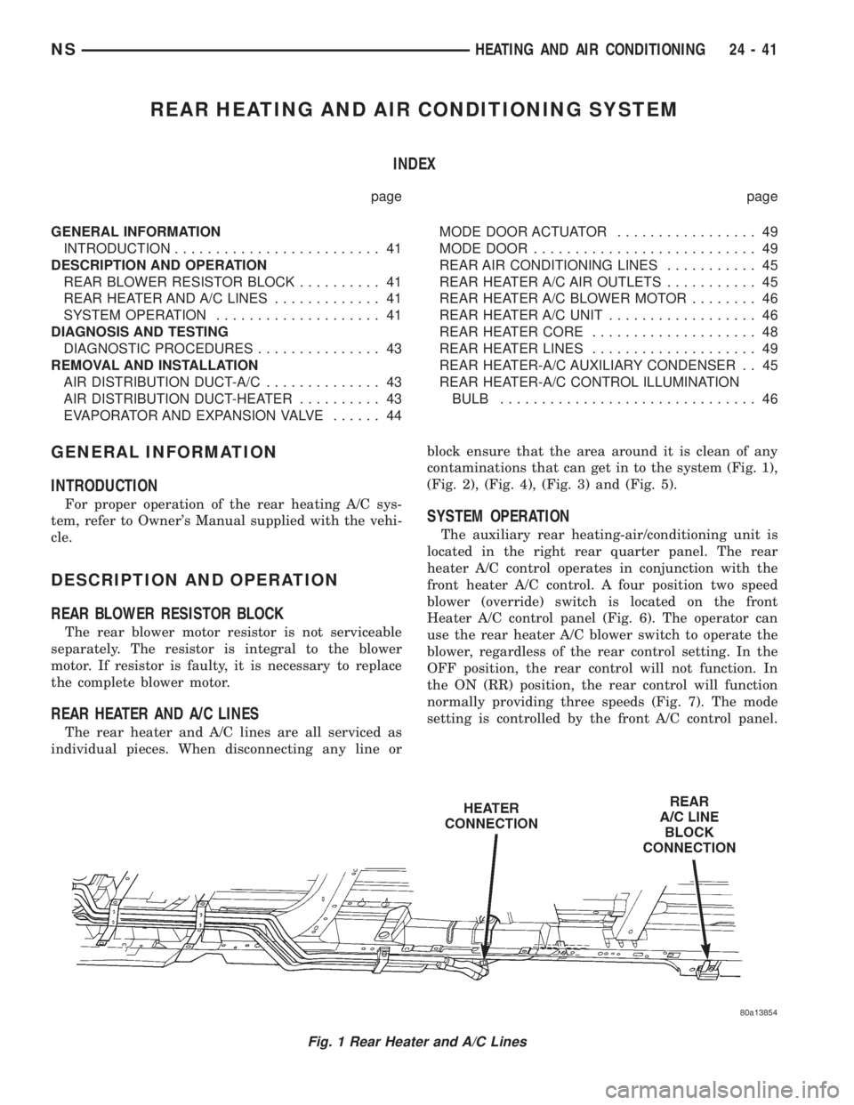
individual pieces. When disconnecting any line orblock ensure that the area around it is clean of any
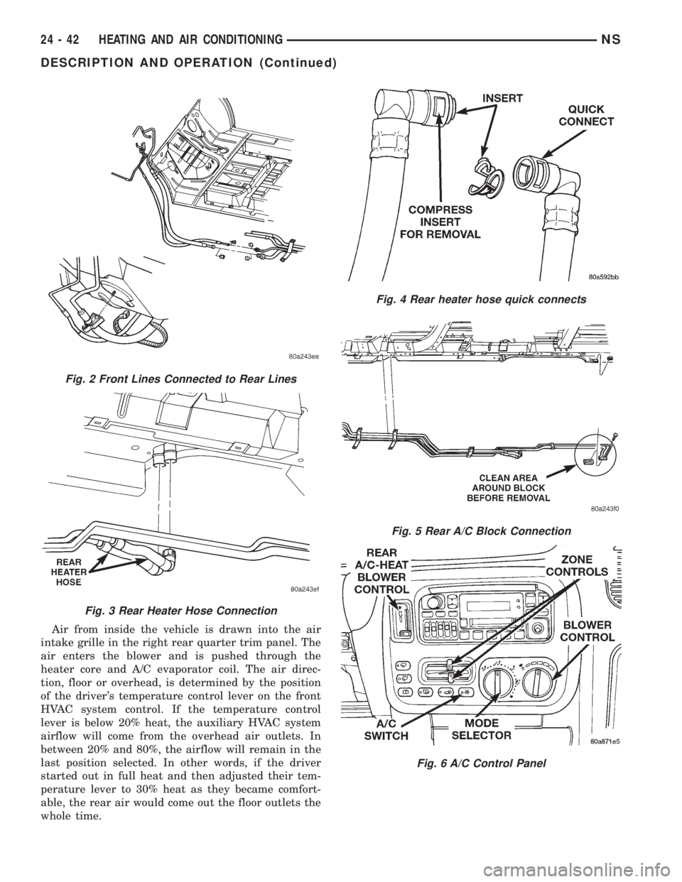
contaminations that can get in to the system (Fig. 1),
(Fig. 2), (Fig. 4), (Fig. 3) and (Fig. 5).
SYSTEM OPERATION
The auxiliary rear heating-air/conditioning unit is
located in the right rear quarter panel. The rear
heater A/C control operates in conjunction with the
front heater A/C control. A four position two speed
blower (override) switch is located on the front
Heater A/C control panel (Fig. 6). The operator can
use the rear heater A/C blower switch to operate the
blower, regardless of the rear control setting. In the
OFF position, the rear control will not function. In
the ON (RR) position, the rear control will function
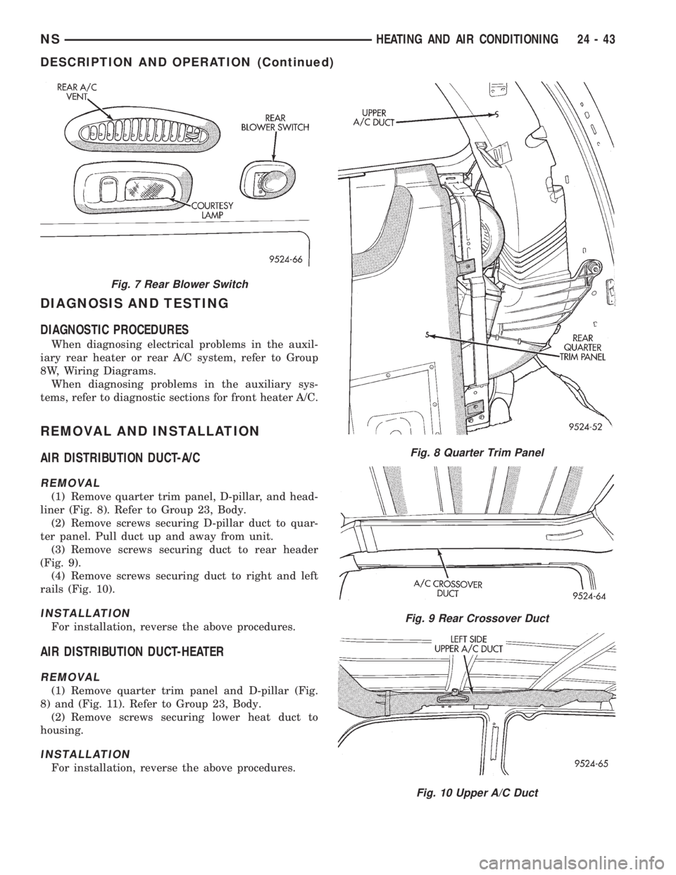
normally providing three speeds (Fig. 7). The mode
setting is controlled by the front A/C control panel.
Fig. 1 Rear Heater and A/C Lines
NSHEATING AND AIR CONDITIONING 24 - 41
Page 1858 of 1938
Air from inside the vehicle is drawn into the air
intake grille in the right rear quarter trim panel. The
air enters the blower and is pushed through the
heater core and A/C evaporator coil. The air direc-
tion, floor or overhead, is determined by the position
of the driver's temperature control lever on the front
HVAC system control. If the temperature control
lever is below 20% heat, the auxiliary HVAC system
airflow will come from the overhead air outlets. In
between 20% and 80%, the airflow will remain in the
last position selected. In other words, if the driver
started out in full heat and then adjusted their tem-
perature lever to 30% heat as they became comfort-
able, the rear air would come out the floor outlets the
whole time.
Fig. 2 Front Lines Connected to Rear Lines
Fig. 3 Rear Heater Hose Connection
Fig. 4 Rear heater hose quick connects
Fig. 5 Rear A/C Block Connection
Fig. 6 A/C Control Panel
24 - 42 HEATING AND AIR CONDITIONINGNS
DESCRIPTION AND OPERATION (Continued)
Page 1859 of 1938
DIAGNOSIS AND TESTING
DIAGNOSTIC PROCEDURES
When diagnosing electrical problems in the auxil-
iary rear heater or rear A/C system, refer to Group
8W, Wiring Diagrams.
When diagnosing problems in the auxiliary sys-
tems, refer to diagnostic sections for front heater A/C.
REMOVAL AND INSTALLATION
AIR DISTRIBUTION DUCT-A/C
REMOVAL
(1) Remove quarter trim panel, D-pillar, and head-
liner (Fig. 8). Refer to Group 23, Body.
(2) Remove screws securing D-pillar duct to quar-
ter panel. Pull duct up and away from unit.
(3) Remove screws securing duct to rear header
(Fig. 9).
(4) Remove screws securing duct to right and left
rails (Fig. 10).
INSTALLATION
For installation, reverse the above procedures.
AIR DISTRIBUTION DUCT-HEATER
REMOVAL
(1) Remove quarter trim panel and D-pillar (Fig.
8) and (Fig. 11). Refer to Group 23, Body.
(2) Remove screws securing lower heat duct to
housing.
INSTALLATION
For installation, reverse the above procedures.
Fig. 7 Rear Blower Switch
Fig. 8 Quarter Trim Panel
Fig. 9 Rear Crossover Duct
Fig. 10 Upper A/C Duct
NSHEATING AND AIR CONDITIONING 24 - 43
DESCRIPTION AND OPERATION (Continued)
Page 1860 of 1938
EVAPORATOR AND EXPANSION VALVE
NOTE: Special effort must be used to keep all
R-134a system components moisture-free. Moisture
in the oil is very difficult to remove and will cause a
reliability problem with the compressor.
REMOVAL
WARNING: THE REFRIGERANT SYSTEM MUST BE
EMPTY BEFORE PERFORMING THE FOLLOWING
OPERATION. THE ENGINE COOLING SYSTEM
MUST ALSO BE RELIEVED OF ALL PRESSURE.
(1) Remove right quarter trim panel and D-pillar
trim. Refer to Group 23, Body.
(2) Remove fan A/C distribution duct.
(3) Remove rear A/C unit.
(4) Remove blower scroll.
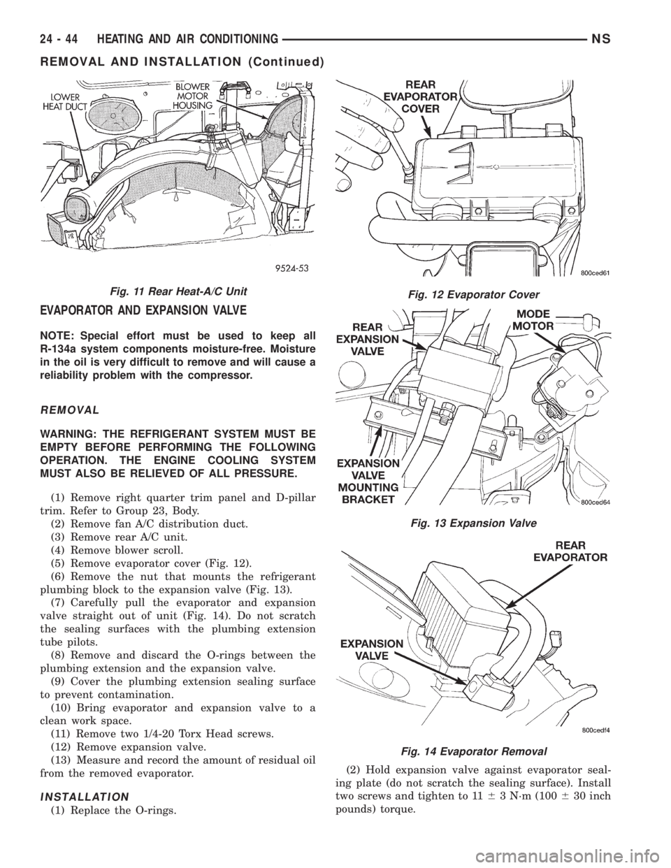
(5) Remove evaporator cover (Fig. 12).
(6) Remove the nut that mounts the refrigerant
plumbing block to the expansion valve (Fig. 13).
(7) Carefully pull the evaporator and expansion
valve straight out of unit (Fig. 14). Do not scratch
the sealing surfaces with the plumbing extension
tube pilots.
(8) Remove and discard the O-rings between the
plumbing extension and the expansion valve.
(9) Cover the plumbing extension sealing surface
to prevent contamination.
(10) Bring evaporator and expansion valve to a
clean work space.
(11) Remove two 1/4-20 Torx Head screws.
(12) Remove expansion valve.
(13) Measure and record the amount of residual oil
from the removed evaporator.
INSTALLATION
(1) Replace the O-rings.(2) Hold expansion valve against evaporator seal-
ing plate (do not scratch the sealing surface). Install
two screws and tighten to 1163 N´m (100630 inch
pounds) torque.
Fig. 11 Rear Heat-A/C UnitFig. 12 Evaporator Cover
Fig. 13 Expansion Valve
Fig. 14 Evaporator Removal
24 - 44 HEATING AND AIR CONDITIONINGNS
REMOVAL AND INSTALLATION (Continued)