sensor CHRYSLER VOYAGER 1996 Service Manual
[x] Cancel search | Manufacturer: CHRYSLER, Model Year: 1996, Model line: VOYAGER, Model: CHRYSLER VOYAGER 1996Pages: 1938, PDF Size: 55.84 MB
Page 45 of 1938
instructions included with the thread insert for the
detailed procedure used for the installation of the
thread insert.
NOTE: The thread inserts for this application are
for the repair of M8x1.25 and M10x1.5 threads. Be
sure the correct tools are used for the required
thread insert size.
TOOL REQUIREMENT FOR M8x1.25 Thread
²8.3mm (5/16 in.) Drill Bit
²120É Countersink
²Heli-CoiltTap #4863-8
²Heli-CoiltGage #4624-8
²Heli-CoiltHand Inserting Tool 7751-8
²Needle Nose Pliers ± For Removal Of Thread
Insert Driving Tang
TOOL REQUIREMENT FOR M10x1.5 Thread
²10.5mm (25/64 in.) Drill Bit
²120É Countersink
²Heli-CoiltTap #4863-10
²Heli-CoiltGage #4624-10
²Heli-CoiltHand Inserting Tool 7751-10
²Needle Nose Pliers ± For Removal Of Thread
Insert Driving Tang
REMOVAL AND INSTALLATION
Mc PHERSON STRUT
REMOVAL
WARNING: DO NOT REMOVE THE NUT FROM THE
STRUT ROD WHILE STRUT ASSEMBLY IS
INSTALLED IN VEHICLE, OR BEFORE STRUT
ASSEMBLY SPRING IS COMPRESSED.
(1) Raise vehicle on jack stands or centered on a
frame contact type hoist. See Hoisting in the Lubri-
cation and Maintenance section of this service man-
ual, for the required lifting procedure to be used for
this vehicle.
(2) Remove the wheel and tire assembly from loca-
tion on front of vehicle requiring strut removal.
(3) If both strut assemblies are to be removed,
mark the strut assemblies right or left according to
which side of the vehicle they were removed from.
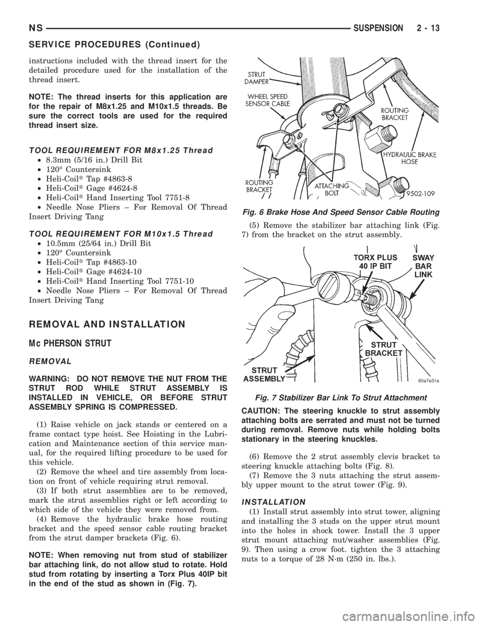
(4) Remove the hydraulic brake hose routing
bracket and the speed sensor cable routing bracket
from the strut damper brackets (Fig. 6).
NOTE: When removing nut from stud of stabilizer
bar attaching link, do not allow stud to rotate. Hold
stud from rotating by inserting a Torx Plus 40IP bit
in the end of the stud as shown in (Fig. 7).(5) Remove the stabilizer bar attaching link (Fig.
7) from the bracket on the strut assembly.
CAUTION: The steering knuckle to strut assembly
attaching bolts are serrated and must not be turned
during removal. Remove nuts while holding bolts
stationary in the steering knuckles.
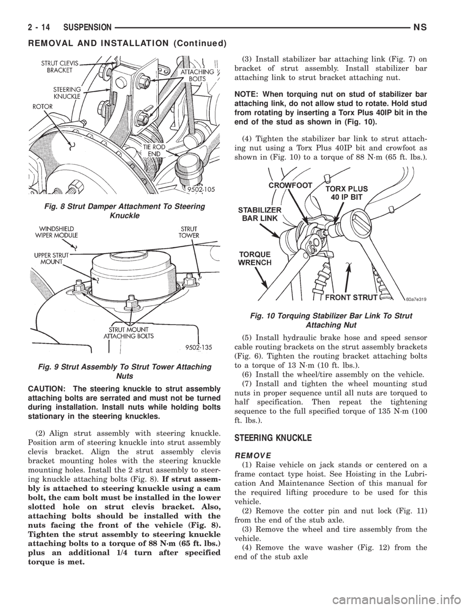
(6) Remove the 2 strut assembly clevis bracket to
steering knuckle attaching bolts (Fig. 8).
(7) Remove the 3 nuts attaching the strut assem-
bly upper mount to the strut tower (Fig. 9).
INSTALLATION
(1) Install strut assembly into strut tower, aligning
and installing the 3 studs on the upper strut mount
into the holes in shock tower. Install the 3 upper
strut mount attaching nut/washer assemblies (Fig.
9). Then using a crow foot. tighten the 3 attaching
nuts to a torque of 28 N´m (250 in. lbs.).
Fig. 6 Brake Hose And Speed Sensor Cable Routing
Fig. 7 Stabilizer Bar Link To Strut Attachment
NSSUSPENSION 2 - 13
SERVICE PROCEDURES (Continued)
Page 46 of 1938
CAUTION: The steering knuckle to strut assembly
attaching bolts are serrated and must not be turned
during installation. Install nuts while holding bolts
stationary in the steering knuckles.
(2) Align strut assembly with steering knuckle.
Position arm of steering knuckle into strut assembly
clevis bracket. Align the strut assembly clevis
bracket mounting holes with the steering knuckle
mounting holes. Install the 2 strut assembly to steer-
ing knuckle attaching bolts (Fig. 8).If strut assem-
bly is attached to steering knuckle using a cam
bolt, the cam bolt must be installed in the lower
slotted hole on strut clevis bracket. Also,
attaching bolts should be installed with the
nuts facing the front of the vehicle (Fig. 8).
Tighten the strut assembly to steering knuckle
attaching bolts to a torque of 88 N´m (65 ft. lbs.)
plus an additional 1/4 turn after specified
torque is met.(3) Install stabilizer bar attaching link (Fig. 7) on
bracket of strut assembly. Install stabilizer bar
attaching link to strut bracket attaching nut.
NOTE: When torquing nut on stud of stabilizer bar
attaching link, do not allow stud to rotate. Hold stud
from rotating by inserting a Torx Plus 40IP bit in the
end of the stud as shown in (Fig. 10).
(4) Tighten the stabilizer bar link to strut attach-
ing nut using a Torx Plus 40IP bit and crowfoot as
shown in (Fig. 10) to a torque of 88 N´m (65 ft. lbs.).
(5) Install hydraulic brake hose and speed sensor
cable routing brackets on the strut assembly brackets
(Fig. 6). Tighten the routing bracket attaching bolts
to a torque of 13 N´m (10 ft. lbs.).
(6) Install the wheel/tire assembly on the vehicle.
(7) Install and tighten the wheel mounting stud
nuts in proper sequence until all nuts are torqued to
half specification. Then repeat the tightening
sequence to the full specified torque of 135 N´m (100
ft. lbs.).
STEERING KNUCKLE
REMOVE
(1) Raise vehicle on jack stands or centered on a
frame contact type hoist. See Hoisting in the Lubri-
cation And Maintenance Section of this manual for
the required lifting procedure to be used for this
vehicle.
(2) Remove the cotter pin and nut lock (Fig. 11)
from the end of the stub axle.
(3) Remove the wheel and tire assembly from the
vehicle.
(4) Remove the wave washer (Fig. 12) from the
end of the stub axle
Fig. 8 Strut Damper Attachment To Steering
Knuckle
Fig. 9 Strut Assembly To Strut Tower Attaching
Nuts
Fig. 10 Torquing Stabilizer Bar Link To Strut
Attaching Nut
2 - 14 SUSPENSIONNS
REMOVAL AND INSTALLATION (Continued)
Page 48 of 1938
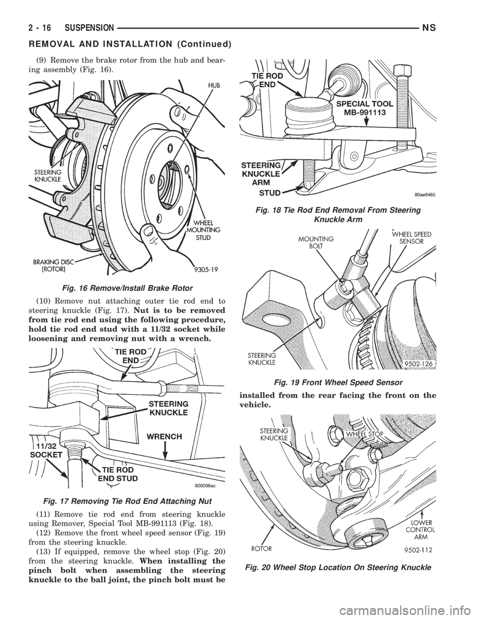
(9) Remove the brake rotor from the hub and bear-
ing assembly (Fig. 16).
(10) Remove nut attaching outer tie rod end to
steering knuckle (Fig. 17).Nut is to be removed
from tie rod end using the following procedure,
hold tie rod end stud with a 11/32 socket while
loosening and removing nut with a wrench.
(11) Remove tie rod end from steering knuckle
using Remover, Special Tool MB-991113 (Fig. 18).
(12) Remove the front wheel speed sensor (Fig. 19)
from the steering knuckle.
(13) If equipped, remove the wheel stop (Fig. 20)
from the steering knuckle.When installing the
pinch bolt when assembling the steering
knuckle to the ball joint, the pinch bolt must beinstalled from the rear facing the front on the
vehicle.
Fig. 16 Remove/Install Brake Rotor
Fig. 17 Removing Tie Rod End Attaching Nut
Fig. 18 Tie Rod End Removal From Steering
Knuckle Arm
Fig. 19 Front Wheel Speed Sensor
Fig. 20 Wheel Stop Location On Steering Knuckle
2 - 16 SUSPENSIONNS
REMOVAL AND INSTALLATION (Continued)
Page 50 of 1938
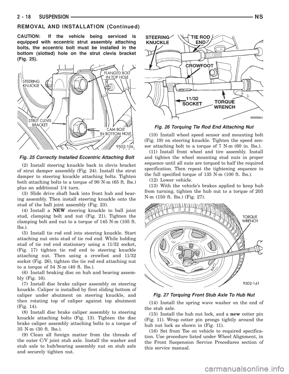
CAUTION: If the vehicle being serviced is
equipped with eccentric strut assembly attaching
bolts, the eccentric bolt must be installed in the
bottom (slotted) hole on the strut clevis bracket
(Fig. 25).
(2) Install steering knuckle back in clevis bracket
of strut damper assembly (Fig. 24). Install the strut
damper to steering knuckle attaching bolts. Tighten
both attaching bolts to a torque of 90 N´m (65 ft. lbs.)
plus an additional 1/4 turn.
(3) Slide drive shaft back into front hub and bear-
ing assembly. Then install steering knuckle onto the
stud of the ball joint assembly (Fig. 23).
(4) Install aNEWsteering knuckle to ball joint
stud, clamping bolt and nut (Fig. 21). Tighten the
clamping bolt and nut to a torque of 145 N´m (105 ft.
lbs.).
(5) Install tie rod end into steering knuckle. Start
attaching nut onto stud of tie rod end. While holding
stud of tie rod end stationary using a 11/32 socket,
(Fig. 17) tighten tie rod end to steering knuckle
attaching nut. Then using a crowfoot and 11/32
socket (Fig. 26), tighten the tie rod end attaching nut
to a torque of 54 N´m (40 ft. lbs.).
(6) Install braking disc on hub and bearing assem-
bly (Fig. 16).
(7) Install disc brake caliper assembly on steering
knuckle. Caliper is installed by first sliding bottom of
caliper under abutment on steering knuckle, and
then rotating top of caliper against top abutment
(Fig. 14).
(8) Install disc brake caliper assembly to steering
knuckle attaching bolts (Fig. 13). Tighten the disc
brake caliper assembly attaching bolts to a torque of
35 N´m (30 ft. lbs.).
(9) Clean all foreign matter from the threads of
the outer C/V joint stub axle. Install the washer and
stub axle to hub/bearing assembly nut on stub axle
and securely tighten nut.(10) Install wheel speed sensor and mounting bolt
(Fig. 19) on steering knuckle. Tighten the speed sen-
sor attaching bolt to a torque of 7 N´m (60 in. lbs.).
(11)
Install front wheel and tire assembly. Install
and tighten the wheel mounting stud nuts in proper
sequence until all nuts are torqued to half the required
specification. Then repeat the tightening sequence to
the full specified torque of 135 N´m (100 ft. lbs.).
(12) Lower vehicle.
(13) With the vehicle's brakes applied to keep hub
from turning, tighten the hub nut to a torque of 203
N´m (150 ft. lbs.) (Fig. 27).
(14) Install the spring wave washer on the end of
the stub axle.
(15) Install the hub nut lock, and anewcotter pin
(Fig. 11). Wrap cotter pin prongs tightly around the
hub nut lock as shown in (Fig. 11).
(16) Set front Toe on vehicle to required specifica-
tion. Use procedure listed under Wheel Alignment, in
the Front Suspension Service Procedures section of
this service manual.
Fig. 25 Correctly Installed Eccentric Attaching Bolt
Fig. 26 Torquing Tie Rod End Attaching Nut
Fig. 27 Torquing Front Stub Axle To Hub Nut
2 - 18 SUSPENSIONNS
REMOVAL AND INSTALLATION (Continued)
Page 72 of 1938
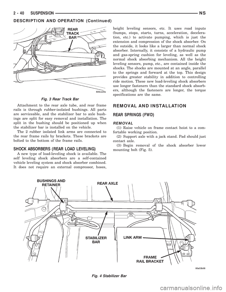
Attachment to the rear axle tube, and rear frame
rails is through rubber-isolated bushings. All parts
are serviceable, and the stabilizer bar to axle bush-
ings are split for easy removal and installation. The
split in the bushing should be positioned up when
the stabilizer bar is installed on the vehicle.
The 2 rubber isolated link arms are connected to
the rear frame rails by brackets. These brackets are
bolted to the bottom of the frame rails.
SHOCK ABSORBERS (REAR LOAD LEVELING)
A new type of load-leveling shock is available. The
self leveling shock absorbers are a self-contained
vehicle leveling system and shock absorber combined.
It does not require an external compressor, hoses,height leveling sensors, etc. It uses road inputs
(bumps, stops, starts, turns, acceleration, decelera-
tion, etc.) to activate pumping, which is just the
extension and compression of the shock absorber. On
the outside, it looks like a larger than normal shock
absorber. Internally, it consists of a hydraulic pump
and gas-spring cushion for leveling, as well as the
normal shock absorbing mechanism. All the height
leveling sensors, pump, etc., are contained inside the
shocks. The shocks are mounted at an angle, parallel
to the springs and forward at the top. This design
provides greater stability in addition to controlling
ride motion. These new load-leveling shock absorbers
use longer fasteners than the standard shock absorb-
ers, although the fasteners are longer, the torque
specifications are the same.
REMOVAL AND INSTALLATION
REAR SPRINGS (FWD)
REMOVAL
(1) Raise vehicle on frame contact hoist to a com-
fortable working position.
(2) Support axle with a jack stand. Pad should just
contact axle.
(3) Begin removal of the shock absorber lower
mounting bolt (Fig. 5).
Fig. 4 Stabilizer Bar
Fig. 3 Rear Track Bar
2 - 40 SUSPENSIONNS
DESCRIPTION AND OPERATION (Continued)
Page 83 of 1938
BRAKES
CONTENTS
page page
ANTILOCK BRAKE SYSTEM ±
TEVES MARK-20....................... 85BASE BRAKE SYSTEM..................... 3
GENERAL INFORMATION................... 1
GENERAL INFORMATION
INDEX
page page
GENERAL INFORMATION
BASE BRAKE SYSTEM COMPONENT
DESCRIPTION......................... 1GENERAL VEHICLE SERVICE CAUTIONS...... 1
GENERAL INFORMATION
GENERAL VEHICLE SERVICE CAUTIONS
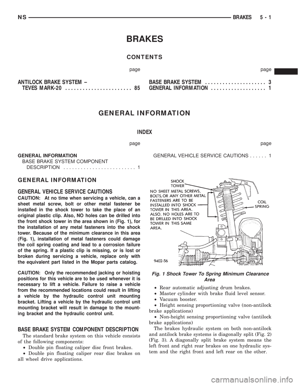
CAUTION: At no time when servicing a vehicle, can a
sheet metal screw, bolt or other metal fastener be
installed in the shock tower to take the place of an
original plastic clip. Also, NO holes can be drilled into
the front shock tower in the area shown in (Fig. 1), for
the installation of any metal fasteners into the shock
tower. Because of the minimum clearance in this area
(Fig. 1), installation of metal fasteners could damage
the coil spring coating and lead to a corrosion failure
of the spring. If a plastic clip is missing, or is lost or
broken during servicing a vehicle, replace only with
the equivalent part listed in the Mopar parts catalog.
CAUTION: Only the recommended jacking or hoisting
positions for this vehicle are to be used whenever it is
necessary to lift a vehicle. Failure to raise a vehicle
from the recommended locations could result in lifting
a vehicle by the hydraulic control unit mounting
bracket. Lifting a vehicle by the hydraulic control unit
mounting bracket will result in damage to the mount-
ing bracket and the hydraulic control unit.
BASE BRAKE SYSTEM COMPONENT DESCRIPTION
The standard brake system on this vehicle consists
of the following components:
²Double pin floating caliper disc front brakes.
²Double pin floating caliper rear disc brakes on
all wheel drive applications.²Rear automatic adjusting drum brakes.
²Master cylinder with brake fluid level sensor.
²Vacuum booster.
²Height sensing proportioning valve (non-antilock
brake applications)
²Non-height sensing proportioning valve (antilock
brake applications)
The brakes hydraulic system on both non-antilock
and antilock brake systems is diagonally split (Fig. 2)
(Fig. 3). A diagonally split brake system means the
left front and right rear brakes on one hydraulic sys-
tem and the right front and left rear on the other.
Fig. 1 Shock Tower To Spring Minimum Clearance
Area
NSBRAKES 5 - 1
Page 90 of 1938
brakes. The secondary outlet port supplies hydraulic
pressure to the left front and right rear brakes.
POWER BRAKE VACUUM BOOSTER OPERATION
All vehicles use a 270 mm single diaphragm power
brake vacuum booster.
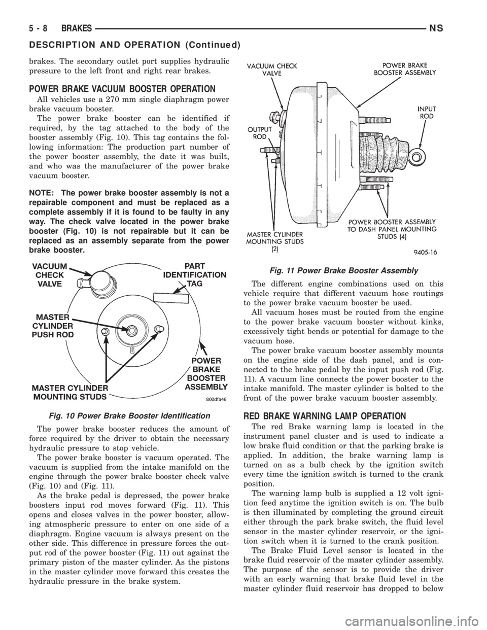
The power brake booster can be identified if
required, by the tag attached to the body of the
booster assembly (Fig. 10). This tag contains the fol-
lowing information: The production part number of
the power booster assembly, the date it was built,
and who was the manufacturer of the power brake
vacuum booster.
NOTE: The power brake booster assembly is not a
repairable component and must be replaced as a
complete assembly if it is found to be faulty in any
way. The check valve located in the power brake
booster (Fig. 10) is not repairable but it can be
replaced as an assembly separate from the power
brake booster.
The power brake booster reduces the amount of
force required by the driver to obtain the necessary
hydraulic pressure to stop vehicle.
The power brake booster is vacuum operated. The
vacuum is supplied from the intake manifold on the
engine through the power brake booster check valve
(Fig. 10) and (Fig. 11).
As the brake pedal is depressed, the power brake
boosters input rod moves forward (Fig. 11). This
opens and closes valves in the power booster, allow-
ing atmospheric pressure to enter on one side of a
diaphragm. Engine vacuum is always present on the
other side. This difference in pressure forces the out-
put rod of the power booster (Fig. 11) out against the
primary piston of the master cylinder. As the pistons
in the master cylinder move forward this creates the
hydraulic pressure in the brake system.The different engine combinations used on this
vehicle require that different vacuum hose routings
to the power brake vacuum booster be used.
All vacuum hoses must be routed from the engine
to the power brake vacuum booster without kinks,
excessively tight bends or potential for damage to the
vacuum hose.
The power brake vacuum booster assembly mounts
on the engine side of the dash panel, and is con-
nected to the brake pedal by the input push rod (Fig.
11). A vacuum line connects the power booster to the
intake manifold. The master cylinder is bolted to the
front of the power brake vacuum booster assembly.
RED BRAKE WARNING LAMP OPERATION
The red Brake warning lamp is located in the
instrument panel cluster and is used to indicate a
low brake fluid condition or that the parking brake is
applied. In addition, the brake warning lamp is
turned on as a bulb check by the ignition switch
every time the ignition switch is turned to the crank
position.
The warning lamp bulb is supplied a 12 volt igni-
tion feed anytime the ignition switch is on. The bulb
is then illuminated by completing the ground circuit
either through the park brake switch, the fluid level
sensor in the master cylinder reservoir, or the igni-
tion switch when it is turned to the crank position.
The Brake Fluid Level sensor is located in the
brake fluid reservoir of the master cylinder assembly.
The purpose of the sensor is to provide the driver
with an early warning that brake fluid level in the
master cylinder fluid reservoir has dropped to below
Fig. 10 Power Brake Booster Identification
Fig. 11 Power Brake Booster Assembly
5 - 8 BRAKESNS
DESCRIPTION AND OPERATION (Continued)
Page 91 of 1938

normal. This may indicate:(1)Abnormal loss of
brake fluid in the master cylinder fluid reservoir
resulting from a leak in the hydraulic system.(2)
Brake shoe linings which have worn to a point
requiring replacement.
As the brake fluid drops below the minimum level,
the brake fluid level sensor closes to ground the
brake warning light circuit. This will turn on the red
brake warning light. At this time, master cylinder
fluid reservoir should be checked and filled to the full
mark with DOT 3 brake fluid.If brake fluid level
has dropped below the add line in the master
cylinder fluid reservoir, the entire brake
hydraulic system should be checked for evi-
dence of a leak.
STOP LAMP SWITCH
The stop lamp switch controls operation of the
vehicles stop lamps. Also, if the vehicle is equippedwith speed control, the stop lamp switch will deacti-
vate speed control when the brake pedal is
depressed.
The stop lamp switch controls operation of the
right and left tail, stop and turn signal lamp and
CHMSL lamp, by supplying battery current to these
lamps.
The stop lamp switch controls the lamp operation
by opening and closing the electrical circuit to the
stop lamps.
HUB/BEARING REAR WHEEL
The rear hub and bearing assembly used on this
vehicle is serviceable only as a complete assembly. No
attempt should be made to disassemble a rear hub
and bearing assembly in an effort to repair it.
The rear hub and bearing assembly is attached to
the rear axle using 4 mounting bolts that are remov-
able from the back of the rear hub/bearing.
DIAGNOSIS AND TESTING
BRAKE SYSTEM BASIC DIAGNOSIS GUIDE
SYMPTOMCHART 1
MISC.
COND.CHART 2
WARNING
LIGHTCHART 3
POWER
BRAKESCHART 4
BRAKE
NOISECHART 5
WHEEL
BRAKES
Brake Warning Light On X NO NO
Excessive Pedal Travel 6 X NO O
Pedal Goes To The Floor 6 X
Stop Light On Without Brakes 3
All Brakes Drag 5
Rear Brakes Drag 2 NO NO
Grabby Brakes O X
Spongy Brake Pedal X NO
Premature Rear Brake Lockup 4 NO NO O
Excessive Pedal Effort 1 O
Rough Engine Idle NO O
Brake Chatter (Rough) NO NO X
Surge During Braking NO NO X
Noise During Braking NO NO X
Rattle Or Clunking Noise NO NO X
Pedal Pulsates During Braking NO NO X
Pull To Right Or Left NO NO X
No: Not A Possible Cause X: Most Likely Cause O: Possible Cause
NSBRAKES 5 - 9
DESCRIPTION AND OPERATION (Continued)
Page 119 of 1938
CAUTION: When installing the tension clip on the
automatic adjuster, it must be located on only the
threaded area of the adjuster assembly (Fig. 66). If
it is located on a non-threaded area of the adjuster,
the function of the automatic adjuster will be
affected.
(7) Install the tension clip (Fig. 66) attaching the
upper return spring to the automatic adjuster assem-
bly.
(8) Install the brake shoe to brake shoe lower
return springs on the brake shoes (Fig. 64) and (Fig.
65).
(9) Install automatic adjustment lever on the lead-
ing brake shoe of the rear brake assembly (Fig. 63).
(10) Install the actuating spring on the automatic
adjustment lever and leading brake shoe assembly
(Fig. 62).
(11) Verify that the automatic adjuster lever has
positive contact with the star wheel on the automatic
adjuster assembly.
(12) When all components of both rear brake
assemblies are correctly and fully installed, remove
the locking pliers from the front park brake cable.
(13) Adjust brake shoes assemblies so as not to
interfere with brake drum installation.
(14) Install the rear brake drums on the hubs.
(15) Adjust rear brake shoes per Adjusting Rear
Brakes procedure in the service adjustments section
of the service manual.
(16) Install the wheel and tire assembly.
(17) Push the park brake pedal to the floor once
and release pedal. This will automatically remove the
slack from and correctly adjust the park brake
cables.
(18) Tighten the wheel mounting stud nuts in
proper sequence until all nuts are torqued to half
specification. Then repeat the tightening sequence to
the full specified torque of 130 N´m (95 ft. lbs.).
(19) Road test vehicle. The automatic adjuster will
continue the brake adjustment during the road test
of the vehicle.
BRAKE SUPPORT PLATE (REAR DRUM BRAKES)
REMOVE
(1) Raise vehicle on jackstands or centered on a
frame contact type hoist. See Hoisting in the Lubri-
cation and Maintenance section of this service man-
ual for required lifting procedure.
(2) Remove wheel and tire.
(3) Remove brake drum from hub/bearing.
(4) Remove brake shoes from brake support plate.
Refer to Rear Brake Shoe Removal in the removal
and installation section in this group of the service
manual for the required procedure.(5) Disconnect the park brake cable from the park
brake actuation lever.
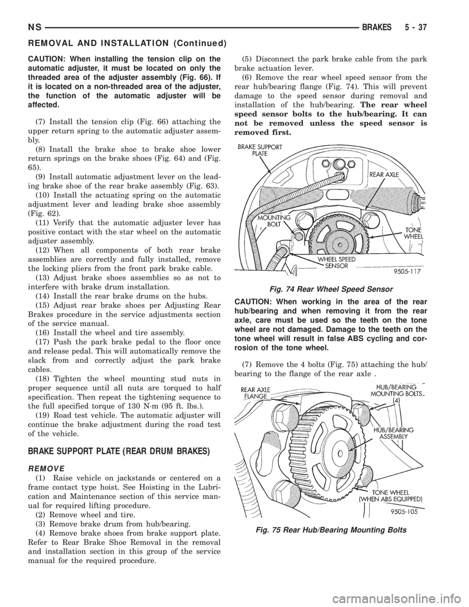
(6) Remove the rear wheel speed sensor from the
rear hub/bearing flange (Fig. 74). This will prevent
damage to the speed sensor during removal and
installation of the hub/bearing.The rear wheel
speed sensor bolts to the hub/bearing. It can
not be removed unless the speed sensor is
removed first.
CAUTION: When working in the area of the rear
hub/bearing and when removing it from the rear
axle, care must be used so the teeth on the tone
wheel are not damaged. Damage to the teeth on the
tone wheel will result in false ABS cycling and cor-
rosion of the tone wheel.
(7) Remove the 4 bolts (Fig. 75) attaching the hub/
bearing to the flange of the rear axle .
Fig. 74 Rear Wheel Speed Sensor
Fig. 75 Rear Hub/Bearing Mounting Bolts
NSBRAKES 5 - 37
REMOVAL AND INSTALLATION (Continued)
Page 121 of 1938
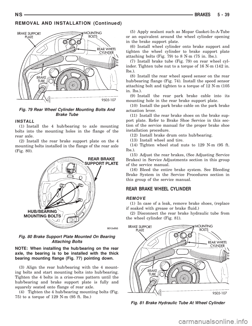
INSTALL
(1) Install the 4 hub/bearing to axle mounting
bolts into the mounting holes in the flange of the
rear axle.
(2) Install the rear brake support plate on the 4
mounting bolts installed in the flange of the rear axle
(Fig. 80).
NOTE: When installing the hub/bearing on the rear
axle, the bearing is to be installed with the thick
bearing mounting flange (Fig. 77) pointing down.
(3) Align the rear hub/bearing with the 4 mount-
ing bolts and start mounting bolts into hub/bearing.
Tighten the 4 bolts in a criss-cross pattern until the
hub/bearing and brake support plate is fully and
squarely seated onto flange of rear axle.
(4) Tighten the 4 hub/bearing mounting bolts (Fig.
75) to a torque of 129 N´m (95 ft. lbs.)(5) Apply sealant such as Mopar Gasket-In-A-Tube
or an equivalent around the wheel cylinder opening
in the brake support plate.
(6) Install wheel cylinder onto brake support and
tighten the wheel cylinder to brake support plate
attaching bolts (Fig. 79) to 8 N´m (75 in. lbs.).
(7) Install brake tube (Fig. 79) on rear wheel cyl-
inder. Tighten tube nut to a torque of 16 N´m (142 in.
lbs.).
(8) Install the rear wheel speed sensor on the rear
hub/bearing flange (Fig. 74). Install the speed sensor
attaching bolt and tighten to a torque of 12 N´m (105
in. lbs.).
(9) Install the rear park brake cable into its
mounting hole in the rear brake support plate.
(10) Install the park brake cable on the park brake
actuation lever.
(11) Install the rear brake shoes on the brake sup-
port plate. Refer to Brake Shoe Service in this sec-
tion of the service manual for the proper brake shoe
installation procedure.
(12) Install brake drum onto hub/bearing.
(13) Install wheel and tire.
(14) Tighten wheel stud nuts to 129 N´m (95 ft.
lbs.).
(15) Adjust the rear brakes, (See Adjusting Service
Brakes) in Service Adjustments section in this group
of the service manual.
(16) Bleed the entire brake system. See Bleeding
Brake System in the Service Procedures section in
this group of the service manual.
REAR BRAKE WHEEL CYLINDER
REMOVE
(1) In case of a leak, remove brake shoes, (replace
if soaked with grease or brake fluid.)
(2) Disconnect the rear brake hydraulic tube from
the wheel cylinder (Fig. 81).
Fig. 79 Rear Wheel Cylinder Mounting Bolts And
Brake Tube
Fig. 80 Brake Support Plate Mounted On Bearing
Attaching Bolts
Fig. 81 Brake Hydraulic Tube At Wheel Cylinder
NSBRAKES 5 - 39
REMOVAL AND INSTALLATION (Continued)