compression ratio CHRYSLER VOYAGER 1996 User Guide
[x] Cancel search | Manufacturer: CHRYSLER, Model Year: 1996, Model line: VOYAGER, Model: CHRYSLER VOYAGER 1996Pages: 1938, PDF Size: 55.84 MB
Page 1165 of 1938
PISTON AND CONNECTING ROD
REMOVAL
(1) Disconnect negative cable from battery.
(2) Remove cylinder heads and oil pan. Refer to
procedure outlined in this section.
(3) Remove top ridge of cylinder bores with a reli-
able ridge reamer before removing pistons from cyl-
inder block.Be sure to keep tops of pistons
covered during this operation. Pistons and con-
necting rods must be removed from top of cyl-
inder block. When removing piston and
connecting rod assemblies from the engine,
rotate crankshaft so that each connecting rod
is centered in cylinder bore.
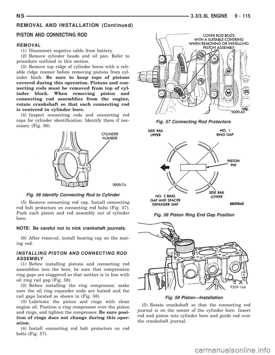
(4) Inspect connecting rods and connecting rod
caps for cylinder identification. Identify them if nec-
essary (Fig. 56).
(5) Remove connecting rod cap. Install connecting
rod bolt protectors on connecting rod bolts (Fig. 57).
Push each piston and rod assembly out of cylinder
bore.
NOTE: Be careful not to nick crankshaft journals.
(6) After removal, install bearing cap on the mat-
ing rod.
INSTALLING PISTON AND CONNECTING ROD
ASSEMBLY
(1) Before installing pistons and connecting rod
assemblies into the bore, be sure that compression
ring gaps are staggered so that neither is in line with
oil ring rail gap (Fig. 58).
(2) Before installing the ring compressor, make
sure the oil ring expander ends are butted and the
rail gaps located as shown in (Fig. 58).
(3) Lubricate the piston and rings with clean
engine oil. Position a ring compressor over the piston
and rings, and tighten the compressor.Be sure posi-
tion of rings does not change during this oper-
ation.
(4) Install connecting rod bolt protectors on rod
bolts (Fig. 57).(5) Rotate crankshaft so that the connecting rod
journal is on the center of the cylinder bore. Insert
rod and piston into cylinder bore and guide rod over
the crankshaft journal.
Fig. 56 Identify Connecting Rod to Cylinder
Fig. 57 Connecting Rod Protectors
Fig. 58 Piston Ring End Gap Position
Fig. 59 PistonÐInstallation
NS3.3/3.8L ENGINE 9 - 115
REMOVAL AND INSTALLATION (Continued)
Page 1173 of 1938
ADJUSTMENTS
ENGINE MOUNTS
ENGINE MOUNT INSULATOR ADJUSTMENT
(1) Remove the load on the engine motor mounts
by carefully supporting the engine and transmission
assembly with a floor jack.
(2) Loosen the right engine mount insulator verti-
cal fastener and the fore and aft fasteners, and the
front engine mount bracket to front crossmember
screws.
(3) Pry the engine right or left as required to
achieve the proper drive shaft assembly length. Refer
to Group 2, Suspension and Driveshafts for drive-
shaft identification and related assembly length mea-
suring.
(4) Tighten engine mounts and fasteners in the
following order:
(a) Right engine mount insulator vertical bolts
to 102 N´m (75 ft. lbs.) and the fore and aft bolts to
150 N´m (110 ft. lbs.).
(b) Front engine mount screws to 54 N´m (40 ft.
lbs.) the clearance between the snubbers and the
engine should be 2 mm (0.078 inch.) each side.
(c) Left engine mount through bolt to 75 N´m (55
ft. lbs.).
(5) Recheck driveshaft length.
SPECIFICATIONS
3.3/3.8L ENGINE
Type.........................60É V-6 Engine
Bore±3.3L..................93.0 mm (3.66 in.)
Bore±3.8L.................96.0 mm (3.779 in.)
Stroke±3.3L...............81.0 mm (3.188 in.)
Stroke±3.8L...............87.0 mm (3.425 in.)
Compression Ratio±3.3L.................8.9:1
Compression Ratio±3.8L.................9.6:1
Displacement±3.3L..........3.3L (201 Cubic in.)
Displacement±3.8L..........3.8L (231 Cubic in.)
Brake Horsepower±3.3L........158 @ 4850 RPM
Brake Horsepower±3.8L........180 @ 4400 RPM
Torque±3.3L............203 lb. ft. @ 3600 RPM
Torque±3.8L............240 lb. ft. @ 3600 RPM
Firing Order....................1±2±3±4±5±6
Compression Pressure.Refer to Engine Performance
in Standard Service Procedures.
Cylinder Number (Front to Rear)
Front Bank...........................2,4,6
Rear Bank............................1,3,6
Cylinder Block
Cylinder Bore (Standard)±3.3L.........93.0 mm
(3.66 in.)
Cylinder Bore (Standard)±3.8L.........96.0 mm
(3.779 in.)
Out-of-Round (Max.)........0.076 mm (0.003 in.)
Taper (Max.)..............0.051 mm (0.002 in.)
Cylinder Bore Oversize (Max.).........0.508 mm
(0.020 in.)
Tappet Bore Diameter.....22.9896 - 23.0099 mm
(0.9051 - 0.9059 in.)
Pistons
Type Material.......Aluminum Alloy Tin Coated
Clearance at Size Location......0.025 - 0.057 mm
(0.001 - 0.0022 in.)
Weight (Standard Only)±3.3L......38165 grams
(13.439460.1764 oz.)
Weight (Standard Only)±3.8L......43865 grams
(15.450160.1764 oz.)
Pistons for Service..............Standard Only
Piston Pins
Type .......................Press Fit in Rod
(Serviced as an Assembly)
Diameter.........................22.88 mm
(0.9009 - 0.9007 in.)
Length±3.3L................67.25 - 67.75 mm
(2.648 - 2.667 in.)
Lenth±3.8L.................71.25 - 71.75 mm
(2.805 - 2.824 in.)
Clearance in Piston @ 70É......0.006 - 0.019 mm
(0.0002 - 0.0007 in.)
Clearance in Rod................(Interference)
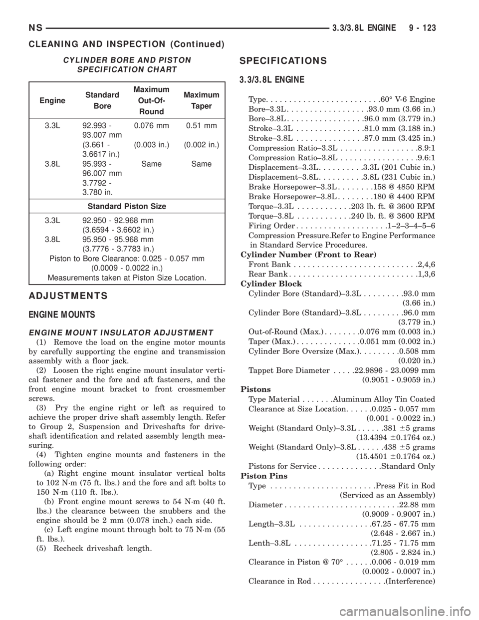
CYLINDER BORE AND PISTON
SPECIFICATION CHART
EngineStandard
BoreMaximum
Out-Of-
RoundMaximum
Taper
3.3L 92.993 -
93.007 mm0.076 mm 0.51 mm
(3.661 -
3.6617 in.)(0.003 in.) (0.002 in.)
3.8L 95.993 -
96.007 mmSame Same
3.7792 -
3.780 in.
Standard Piston Size
3.3L 92.950 - 92.968 mm
(3.6594 - 3.6602 in.)
3.8L 95.950 - 95.968 mm
(3.7776 - 3.7783 in.)
Piston to Bore Clearance: 0.025 - 0.057 mm
(0.0009 - 0.0022 in.)
Measurements taken at Piston Size Location.
NS3.3/3.8L ENGINE 9 - 123
CLEANING AND INSPECTION (Continued)
Page 1174 of 1938
Piston Rings
Number of Rings..........................3
Compression.............................2
Oil Control..............................1
Oil Ring Type . . .3±Piece, Steel Rail, Chrome Face
Piston Ring Gap
Top & 2nd Compression ing.......0.30 - 0.55 mm
(0.0118 - 0.0217 in.)
Oil Control (Steel Rails).........0.25 - 1.00 mm
(0.0098 - 0.0394 in.)
Service Rings
Ring Gap±Compression........0.300 - 0.550 mm
(0.0118 - 0.0217 in.)
Ring Gap±Oil Control..........0.250 - 1.00 mm
(0.0098 - 0.0394 in.)
Piston Ring Side Clearance
Top & 2nd Compression Rings . . .0.030 - 0.095 mm
(0.0012 - 0.0037 in.)
Oil Ring (Steel Rails)..........0.014 - 0.226 mm
(0.0005 - 0.0089 in.)
Piston Ring Width
Compression Rings.............1.46 - 1.50 mm
(0.0575 - 0.0591 in.)
Oil Ring (Steel Rails)................0.510 mm
(0.0201 in.)
Connecting Rods
Bearing Type.........Aluminum Lead (Bimetal)
Bearing Clearance............0.019 - 0.065 mm
(0.00075 - 0.0026 in.)
Max. Allowable..........0.076 mm (0.003 in.)
Side Clearance..............0.127 - 0.381 mm
(0.005 - 0.015 in.)
Crankshaft
Type......................Cast Nodular Iron
Bearing Type.........Aluminum Lead (Bimetal)
Thrust Location.................No. 2 Bearing
Connecting Rod
Journal Diameter..........53.950 - 53.975 mm
(2.124 - 2.125 in.)
Main Bearing Diametrical
Clearance No. 1- 4............0.011 - 0.059 mm
(0.0043 - 0.0023 in.)
Max. Allowable..........0.102 mm (0.004 in.)
End Play.....0.09 - 0.24 mm (0.0036 - 0.0095 in.)
Max. Allowable..........0.381 mm (0.015 in.)
Main Bearing Journals
Diameter.................64.013 - 63.993 mm
(2.5202 - 2.5195 in.)
Out-of-Round (Max.)........0.025 mm (0.001 in.)
Taper (Max.)..............0.025 mm (0.001 in.)
Connecting Rod Journals
Diameter.................58.005 - 57.979 mm
(2.2837 - 2.2827 in.)
Out-of-Round (Max.)........0.025 mm (0.001 in.)
Taper (Max.)..............0.025 mm (0.001 in.)Camshaft
Drive...............................Chain
Bearings.................Steel Backed Babbitt
Number.................................4
Diametrical Clearance.........0.025 - 0.101 mm
(0.001 - 0.004 in.)
Max. Allowable..........0.127 mm (0.005 in.)
Thrust Taken By.................Thrust Plate
End Play...................0.127 - 0.304 mm
(0.005 - 0.012 in.)
Max. Allowable..........0.304 mm (0.012 in.)
Camshaft Journals
Bearing Journal
Diameter No. 1............50.724 - 50.775 mm
(1.997 - 1.999 in.)
Bearing Journal
Diameter No. 2............50.317 - 50.368 mm
(1.9809 - 1.9829 in.)
Bearing Journal
Diameter No. 3............49.936 - 49.987 mm
(1.9659 - 1.9679 in.)
Bearing Journal
Diameter No. 4............49.530 - 49.581 mm
(1.9499 - 1.9520 in.)
Camshaft Bearings
Diameter No. 1.............50.825 - 50.800 mm
(2.0009 - 1.9999 in.)
Diameter No. 2.............50.419 - 50.393 mm
(1.9849 - 1.9839 in.)
Diameter No. 3.............50.038 - 50.013 mm
(1.9699 - 1.9690 in.)
Diameter No. 4.............49.632 - 49.606 mm
(1.954 - 1.9529 in.)
Oil Clearance..............0.0254 - 0.0762 mm
(0.001 - 0.003 in.)
Valve Timing Exhaust Valve
Closes (ATC)...........................12É
Opens (BBC)...........................48É
Duration.............................240É
Valve Timing Intake Valve
Closes (BTDC)..........................58É
Opens.................................2É
Duration.............................240É
Valve Overlap..........................14É
Timing Chain
Number of Links.........................64
Pitch............................0.375 inch
Width...........................0.750 inch
Hydraulic Tappets
Type .......................Roller Hydraulic
Body Diameter...............22.95 - 22.96 mm
(0.9035 - 0.9040 in.)
Clearance in Block..............0.02 - 0.06 mm
(0.0007 - 0.0024 in.)
9 - 124 3.3/3.8L ENGINENS
SPECIFICATIONS (Continued)
Page 1180 of 1938
GENERAL SPECIFICATION
Type .............In-Line OHV, DOHC & SOHC
Bore.....................87.5mm (3.445 Inch)
Stroke...................83.0mm (3.268 inch)
Compression Ratio....DOHC - 9.6:1 SOHC - 9.8:1
Displacement.........2.0Liters (122 Cubic Inch)
Firing Order........................1,3,4,2
Compression Pressure...........1172-1551 kPa
(170 - 225 psi)
Maximum Variation Between Cylinders......25%
Lubrication . . . Pressure Feed - Full Flow Filtration
(Crankshaft Driven Pump)
Engine Oil Capacity . . Refer to Group 0, Lubrication
and Maintenance
ENGINE LUBRICATION SYSTEM
ENGINE LUBRICATION
Refer to Group 0, Lubrication and Maintenance for
recommended oil to be used in various engine appli-
cation. System is full flow filtration, pressure feed
type. The oil pump is mounted in the front engine
cover and driven by the crankshaft. Pressurized oil is
then routed through the main oil gallery, running the
length of the cylinder block, supplying main and rodbearings with further routing. Rod bearing oil throw-
off lubricates the pistons from directed slots on the
side of the connecting rod assemblies. Camshaft and
valve mechanisms are lubricated from a full-length
cylinder head oil gallery supplied from the crankcase
main oil gallery.
PRESSURE LUBRICATION
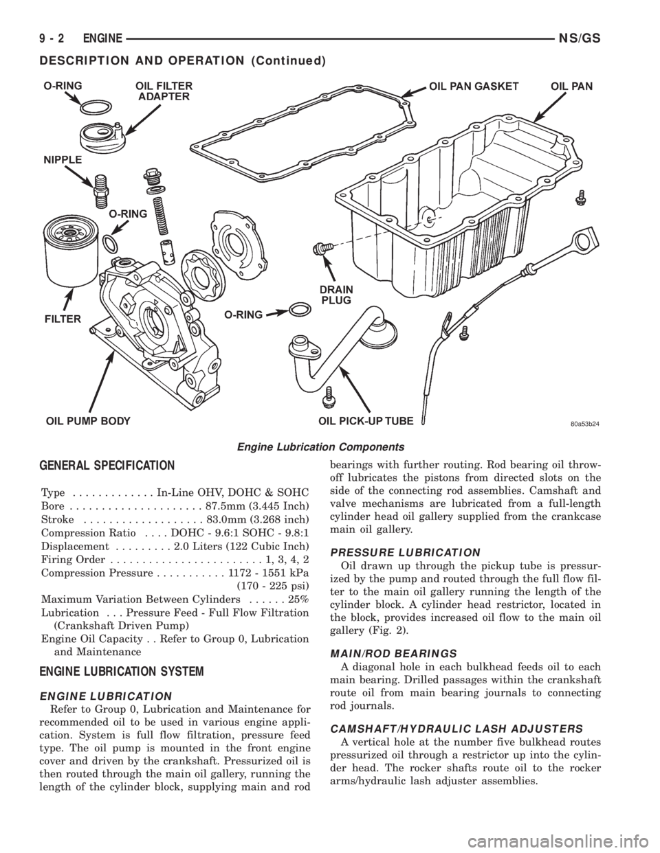
Oil drawn up through the pickup tube is pressur-
ized by the pump and routed through the full flow fil-
ter to the main oil gallery running the length of the
cylinder block. A cylinder head restrictor, located in
the block, provides increased oil flow to the main oil
gallery (Fig. 2).
MAIN/ROD BEARINGS
A diagonal hole in each bulkhead feeds oil to each
main bearing. Drilled passages within the crankshaft
route oil from main bearing journals to connecting
rod journals.
CAMSHAFT/HYDRAULIC LASH ADJUSTERS
A vertical hole at the number five bulkhead routes
pressurized oil through a restrictor up into the cylin-
der head. The rocker shafts route oil to the rocker
arms/hydraulic lash adjuster assemblies.
Engine Lubrication Components
9 - 2 ENGINENS/GS
DESCRIPTION AND OPERATION (Continued)
Page 1181 of 1938
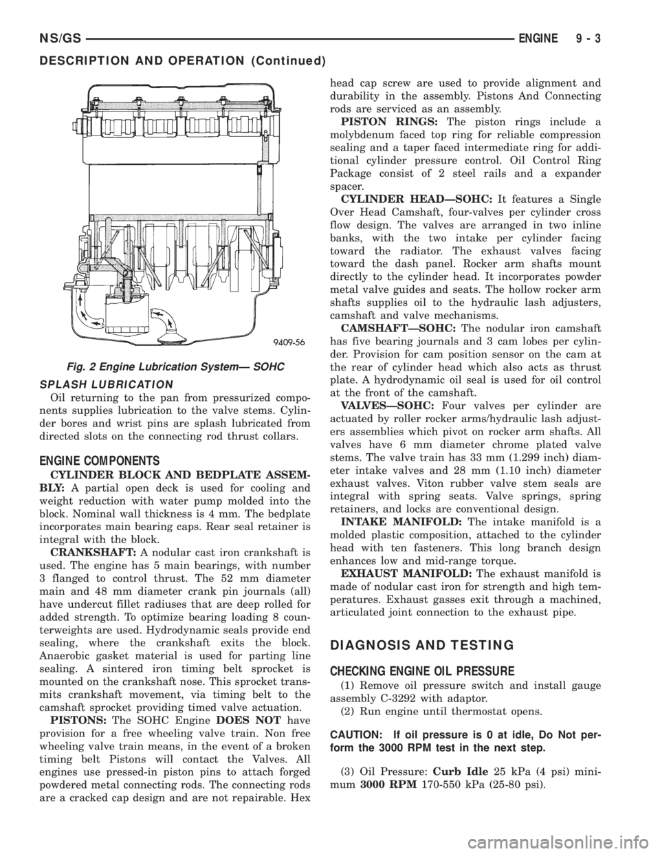
SPLASH LUBRICATION
Oil returning to the pan from pressurized compo-
nents supplies lubrication to the valve stems. Cylin-
der bores and wrist pins are splash lubricated from
directed slots on the connecting rod thrust collars.
ENGINE COMPONENTS
CYLINDER BLOCK AND BEDPLATE ASSEM-
B LY:A partial open deck is used for cooling and
weight reduction with water pump molded into the
block. Nominal wall thickness is 4 mm. The bedplate
incorporates main bearing caps. Rear seal retainer is
integral with the block.
CRANKSHAFT:A nodular cast iron crankshaft is
used. The engine has 5 main bearings, with number
3 flanged to control thrust. The 52 mm diameter
main and 48 mm diameter crank pin journals (all)
have undercut fillet radiuses that are deep rolled for
added strength. To optimize bearing loading 8 coun-
terweights are used. Hydrodynamic seals provide end
sealing, where the crankshaft exits the block.
Anaerobic gasket material is used for parting line
sealing. A sintered iron timing belt sprocket is
mounted on the crankshaft nose. This sprocket trans-
mits crankshaft movement, via timing belt to the
camshaft sprocket providing timed valve actuation.
PISTONS:The SOHC EngineDOES NOThave
provision for a free wheeling valve train. Non free
wheeling valve train means, in the event of a broken
timing belt Pistons will contact the Valves. All
engines use pressed-in piston pins to attach forged
powdered metal connecting rods. The connecting rods
are a cracked cap design and are not repairable. Hexhead cap screw are used to provide alignment and
durability in the assembly. Pistons And Connecting
rods are serviced as an assembly.
PISTON RINGS:The piston rings include a
molybdenum faced top ring for reliable compression
sealing and a taper faced intermediate ring for addi-
tional cylinder pressure control. Oil Control Ring
Package consist of 2 steel rails and a expander
spacer.
CYLINDER HEADÐSOHC:It features a Single
Over Head Camshaft, four-valves per cylinder cross
flow design. The valves are arranged in two inline
banks, with the two intake per cylinder facing
toward the radiator. The exhaust valves facing
toward the dash panel. Rocker arm shafts mount
directly to the cylinder head. It incorporates powder
metal valve guides and seats. The hollow rocker arm
shafts supplies oil to the hydraulic lash adjusters,
camshaft and valve mechanisms.
CAMSHAFTÐSOHC:The nodular iron camshaft
has five bearing journals and 3 cam lobes per cylin-
der. Provision for cam position sensor on the cam at
the rear of cylinder head which also acts as thrust
plate. A hydrodynamic oil seal is used for oil control
at the front of the camshaft.
VALVESÐSOHC:Four valves per cylinder are
actuated by roller rocker arms/hydraulic lash adjust-
ers assemblies which pivot on rocker arm shafts. All
valves have 6 mm diameter chrome plated valve
stems. The valve train has 33 mm (1.299 inch) diam-
eter intake valves and 28 mm (1.10 inch) diameter
exhaust valves. Viton rubber valve stem seals are
integral with spring seats. Valve springs, spring
retainers, and locks are conventional design.
INTAKE MANIFOLD:The intake manifold is a
molded plastic composition, attached to the cylinder
head with ten fasteners. This long branch design
enhances low and mid-range torque.
EXHAUST MANIFOLD:The exhaust manifold is
made of nodular cast iron for strength and high tem-
peratures. Exhaust gasses exit through a machined,
articulated joint connection to the exhaust pipe.
DIAGNOSIS AND TESTING
CHECKING ENGINE OIL PRESSURE
(1) Remove oil pressure switch and install gauge
assembly C-3292 with adaptor.
(2) Run engine until thermostat opens.
CAUTION: If oil pressure is 0 at idle, Do Not per-
form the 3000 RPM test in the next step.
(3) Oil Pressure:Curb Idle25 kPa (4 psi) mini-
mum3000 RPM170-550 kPa (25-80 psi).
Fig. 2 Engine Lubrication SystemÐ SOHC
NS/GSENGINE 9 - 3
DESCRIPTION AND OPERATION (Continued)
Page 1206 of 1938
on the thrust direction. Staggering ring gap is impor-
tant for oil control.
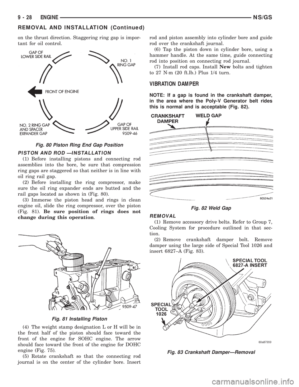
PISTON AND ROD ÐINSTALLATION
(1) Before installing pistons and connecting rod
assemblies into the bore, be sure that compression
ring gaps are staggered so that neither is in line with
oil ring rail gap.
(2) Before installing the ring compressor, make
sure the oil ring expander ends are butted and the
rail gaps located as shown in (Fig. 80).
(3) Immerse the piston head and rings in clean
engine oil, slide the ring compressor, over the piston
(Fig. 81).Be sure position of rings does not
change during this operation.
(4) The weight stamp designation L or H will be in
the front half of the piston should face toward the
front of the engine for SOHC engine. The arrow
should face toward the front of the engine for DOHC
engine (Fig. 75).
(5) Rotate crankshaft so that the connecting rod
journal is on the center of the cylinder bore. Insertrod and piston assembly into cylinder bore and guide
rod over the crankshaft journal.
(6) Tap the piston down in cylinder bore, using a
hammer handle. At the same time, guide connecting
rod into position on connecting rod journal.
(7) Install rod caps. InstallNewbolts and tighten
to 27 N´m (20 ft.lb.) Plus 1/4 turn.
VIBRATION DAMPER
NOTE: If a gap is found in the crankshaft damper,
in the area where the Poly-V Generator belt rides
this is normal and is acceptable (Fig. 82).
REMOVAL
(1) Remove accessory drive belts. Refer to Group 7,
Cooling System for procedure outlined in that sec-
tion.
(2) Remove crankshaft damper bolt. Remove
damper using the large side of Special Tool 1026 and
insert 6827±A (Fig. 83).
Fig. 80 Piston Ring End Gap Position
Fig. 81 Installing Piston
Fig. 82 Weld Gap
Fig. 83 Crankshaft DamperÐRemoval
9 - 28 ENGINENS/GS
REMOVAL AND INSTALLATION (Continued)
Page 1213 of 1938
Cylinder Block
Diameter................20.998 - 21.003 mm
(0.8267 - 0.8269 in.)
End Play............................None
Length.....74.75 - 75.25 mm (2.943 - 2.963 in.)
Piston Rings
Ring Gap Top Compression Ring . . 0.23 - 0.52 mm
(0.009 - 0.020 in.)
Ring Gap 2nd Compression Ring . . 0.49 - 0.78 mm
(0.019 - 0.031 in.)
Ring Gap Oil Control
(Steel Rails) . . . 0.23 - 0.66 mm (0.009 - 0.026 in.)
Ring Side Clearance Both Compression
Rings....0.025 - 0.065 mm (0.0010 - 0.0026 in.)
Oil Ring (Pack).............0.004 - 0.178 mm
(0.0002 - 0.0070 in.)
Ring Width Compression Rings . . . 1.17 - 1.19 mm
(0.046 - 0.047 in.)
Oil Ring (Pack).............2.854 - 3.008 mm
(0.1124 - 0.1184 in.)
Connecting Rod
Bearing Clearance...........0.026 - 0.059 mm
(0.001 - 0.0023 in.)
Piston Pin Bore Diameter.....20.96 - 20.98 mm
(0.8252 - 0.8260 in.)
Large End Bore Diameter . . . 50.991 - 51.005 mm
(2.0075 - 2.0081 in.)
Side Clearance . 0.13 - 0.38 mm (0.005 - 0.015 in.)
Total Weight (Less Bearing) . 543 grams (1.20 lbs.)
Crankshaft
Connecting Rod Journal
Diameter . .
47.9924 - 48.0076 mm (1.8894 - 1.8900 in.)
Out-of-Round (Max.).....0.0035 mm (0.0001 in.)
Taper (Max.)...........0.0038 mm (0.0001 in.)
Main Bearing Diametrical Clearance
No.1-5 ..0.022 - 0.062 mm (0.0008 - 0.0024 in.)
End Play....0.09 - 0.24 mm (0.0035 - 0.0094 in.)
Main Bearing Journals
Diameter..............51.9924 - 52.0076 mm
(2.0469 - 2.0475 in.)
Out-of-Round (Max.).....0.0035 mm (0.0001 in.)
Taper (Max.)...........0.0038 mm (0.0001 in.)
ENGINE 2.0L SOHC
Rocker Arm Shaft
Rocker Arm Shaft Diameter . . 19.996 ± 19.984mm
(0.786 ± 0.7867 in.)
Rocker Arm Shaft Retainers (Width)
Intake (All)...............28.46 mm (1.12 in.)
Exhaust.............1&529.20 mm (1.14in.)
2, 3, and 4 - 40.45 mm (1.59 in.)
Rocker Arm/Hydraulic Lash Adjuster *
Rocker Arm Inside Diameter . . 20.00 ± 20.02 mm
(0.787 ± 0.788 in.)Rocker Arm Shaft Clearance . . . 0.016 ± 0.054 mm
(0.0006 ± 0.0021 in.)
Body Diameter...........22.949 ± 22.962 mm
(0.9035 ± 0.9040 in.)
Plunger Travel Minimum (Dry).........2.2mm
(0.087 in.)
Rocker Arm Ratio...................1.4to1
Cylinder Head Camshaft Bearing Diameter
No.1 ....41.20 ± 41.221 mm (1.622 ± 1.6228 in.)
No.2 ......41.6 ± 41.621 mm (1.637 ± 1.638 in.)
No.3 ......42.0 ± 42.021 mm (1.653 ± 1.654 in.)
No.4 ......42.4 ± 42.421 mm (1.669 ± 1.670 in.)
No.5 .....42.8 ± 42.821 mm (1.685 ± 1.6858 in.)
Camshaft Journal Diameter
No. 1 . . . 41.128 ± 41.147 mm (1.619 ± 1.6199 in.)
No.2 ....41.528 ± 41.547 mm (1.634 ± 1.635 in.)
No.3 ....41.928 ± 41.947 mm (1.650 ± 1.651 in.)
No.4 ....42.328 ± 42.374 mm (1.666 ± 1.668 in.)
No. 5 . . . 42.728 ± 42.747 mm (1.682 ± 1.6829 in.)
Diametrical Bearing Clearance . 0.053 ± 0.093 mm
(0.0027 ± 0.003 in.)
Max. Allowable...........0.12 mm (0.0047 in.)
End Play..........0.05 ± 0.39 mm (0.0059 in.)
Lift (Zero Lash )
Intake...................7.2mm(0.283 in.)
Exhaust.................7.03 mm (0.277 in.)
Valve Timing Exhaust Valve**
Closes (ATDC)........................5.4É
Opens (BBDC).......................43.7É
Duration...........................229.1É
Valve Timing Intake Valve **
Closes (ABDC).......................41.1É
Opens (ATDC)........................13.9É
Duration...........................207.2É
Valve Overlap..........................0É
Cylinder Head
Material....................Cast Aluminum
Gasket Thickness (Compressed).......1.15 mm
(0.045 in.)
Valve Seat
Angle................................45É
Runout (Max.)..............0.050 mm (0.002)
Width (Finish) Intake and
Exhaust.....0.75 ± 1.25 mm (0.030 ± 0.049 in.)
Valve Guide Finished
Diameter I.D. . 5.975 ± 6.000 mm (.235 ± .236 in.)
Guide Bore Diameter (Std.).....11.0±11.02 mm
(0.4330 ± 0.4338 in.)
Valves
Face Angle Intake and Exhaust.....45±45-1/2É
Head Diameter Intake.......32.12 ± 33.37 mm
(1.303 ± 1.313 in.)
Head Diameter Exhaust......28.57 ± 28.83 mm
(1.124 ± 1.135 in.)
NS/GSENGINE 9 - 35
SPECIFICATIONS (Continued)
Page 1218 of 1938
2.5L VM DIESEL
INDEX
page page
GENERAL INFORMATION
ENGINE IDENTIFICATION................ 41
GENERAL SPECIFICATION............... 40
DESCRIPTION AND OPERATION
LUBRICATION SYSTEM.................. 41
DIAGNOSIS AND TESTING
ENGINE DIAGNOSISÐMECHANICAL....... 44
ENGINE DIAGNOSISÐPERFORMANCE..... 43
HYDRAULIC TAPPETS................... 47
SERVICE PROCEDURES
CHANGING ENGINE OIL AND FILTER....... 47
CHECKING OIL LEVEL................... 47
CRANKSHAFT END PLAY................ 50
FITTING PISTON RING.................. 50
TIMING PROCEDURE................... 49
VALVE AND SEAT REFACING............. 49
REMOVAL AND INSTALLATION
CAMSHAFT........................... 62
CAMSHAFT BEARINGS.................. 63
CRANKSHAFT MAIN BEARINGS........... 63
CRANKSHAFTÐREMOVAL............... 72
CYLINDER HEAD....................... 55
CYLINDER HEAD COVER................ 54
CYLINDER LINER...................... 72
ENGINE ASSEMBLY..................... 53
ENGINE MOUNTÐFRONT................ 51
ENGINE MOUNTÐREAR................. 52
ENGINE MOUNTÐRIGHT................ 51
HYDRAULIC TAPPETS................... 60
INJECTION PUMP...................... 61
MOUNTÐLEFT SIDE.................... 51
OIL FILTER ADAPTER AND OIL COOLER.... 68
OILPAN .............................. 66OIL PUMP............................ 67
OIL PUMP PRESSURE RELIEF VALVE...... 67
PISTONS AND CONNECTING ROD......... 68
REAR CRANKSHAFT OIL SEAL............ 72
ROCKER ARMS AND PUSH RODS......... 54
TIMING GEAR COVER................... 61
TIMING GEAR COVER OIL SEAL........... 61
VACUUM PUMP........................ 68
VALVE SPRINGSÐCYLINDER HEAD NOT
REMOVED.......................... 55
VALVES AND VALVE SPRINGSÐHEAD OFF . . 60
VIBRATION DAMPER.................... 61
DISASSEMBLY AND ASSEMBLY
HYDRAULIC TAPPETS................... 73
CLEANING AND INSPECTION
CRANKSHAFT......................... 77
CRANKSHAFT MAIN BEARING............ 77
CYLINDER HEAD....................... 75
CYLINDER HEAD COVERS............... 74
CYLINDER LINER...................... 78
HYDRAULIC TAPPETS................... 76
OILPAN .............................. 78
OIL PUMP............................ 76
PISTON AND CONNECTING ROD.......... 76
ROCKER ARMS AND PUSH RODS......... 74
TIMING GEAR COVER................... 75
VALVES AND VALVE SPRINGS............ 76
SPECIFICATIONS
2.5L VM DIESEL........................ 78
TORQUE............................. 80
SPECIAL TOOLS
2.5L VM DIESEL........................ 81
GENERAL INFORMATION
GENERAL SPECIFICATION
Type ........................425CLIEE (36B)
Displacement...................2.5L (2499 cc)
Bore.............................92.00 mm
Stroke............................94.00 mm
Compression Ratio....................20.95:1
Vacuum at Idle..........600mm/Hg (23.6 In/Hg)
Thermostat Opening................80ÉC62ÉC
Generator Rating............Bosch 50/120 Amp
Cooling System Capacity..............9.5Liter
Power Steering Capacity.............0.75 LiterType ........................425CLIEE (36B)
Engine Oil Capacity.....6.5Liters With Oil Filter
Change
Timing System . Pushrod Operated Overhead valves,
With Gear-Driven Camshaft.
Air Intake........................DryFilter
Fuel Feed...........Vacuum Pump Incorporated
in Injection Pump.
Fuel System.............Indirect Fuel Injection
(Precombustion Chamber)
Combustion Cycle....................4Stroke
Cooling System..................Water Cooled
Injection Pump.......Rotary Pump Electronically
Controlled.
9 - 40 ENGINENS/GS
Page 1221 of 1938
DIAGNOSIS AND TESTING
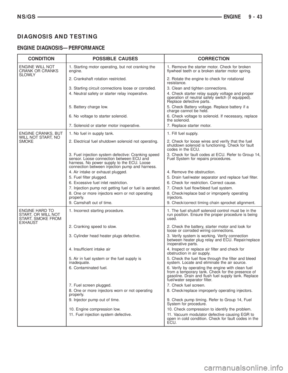
ENGINE DIAGNOSISÐPERFORMANCE
CONDITION POSSIBLE CAUSES CORRECTION
ENGINE WILL NOT
CRANK OR CRANKS
SLOWLY1. Starting motor operating, but not cranking the
engine.1. Remove the starter motor. Check for broken
flywheel teeth or a broken starter motor spring.
2. Crankshaft rotation restricted. 2. Rotate the engine to check for rotational
resistance.
3. Starting circuit connections loose or corroded. 3. Clean and tighten connections.
4. Neutral safety or starter relay inoperative. 4. Check starter relay supply voltage and proper
operation of neutral safety switch (if equipped).
Replace defective parts.
5. Battery charge low. 5. Check Battery voltage. Replace battery if a
charge cannot be held.
6. No voltage to starter solenoid. 6. Check voltage to solenoid. If necessary, replace
the solenoid.
7. Solenoid or starter motor inoperative. 7. Replace starter motor.
ENGINE CRANKS, BUT
WILL NOT START, NO
SMOKE1. No fuel in supply tank. 1. Fill fuel supply.
2. Electrical fuel shutdown solenoid not operating. 2. Check for loose wires and verify that the fuel
shutdown solenoid is functioning. Check for fault
codes in the ECU.
3. Fuel injection system defective: Cranking speed
sensor. Loose connection between ECU and
harness. No power supply to the ECU. Loose
connection between injection pump and harness.3. Check for fault codes at ECU. Refer to Group 14,
Fuel System for repairs procedures.
4. Air intake or exhaust plugged. 4. Remove the obstruction.
5. Fuel filter plugged. 5. Drain fuel/water separator and replace fuel filter.
6. Excessive fuel inlet restriction. 6. Check for restriction. Correct cause.
7. Injection pump not getting fuel or fuel is aerated. 7. Check fuel flow/bleed fuel system.
8. One or more injectors worn or not operating
properly.8. Check/replace bad or improperly operating
injectors.
9. Camshaft out of time. 9. Check/correct timing chain sprocket alignment.
ENGINE HARD TO
START, OR WILL NOT
START, SMOKE FROM
EXHAUST1. Incorrect starting procedure. 1. The fuel shutoff solenoid control must be in the
run position. Ensure the proper procedure is being
used.
2. Cranking speed to slow. 2. Check the battery, starter motor and look for
loose or corroded wiring connections.
3. Cylinder head heater plugs defective. 3. Verify system is working. Verify connection
between heater plug relay and ECU. Repair/replace
inoperative parts.
4. Insufficient intake air 4. Inspect or replace air filter and check for
obstruction in air supply.
5. Air in fuel system or the fuel supply is
inadequate.5. Check the fuel flow through the filter and bleed
system. Locate and eliminate the air source.
6. Contaminated fuel. 6. Verify by operating the engine with clean fuel
from a temporary tank. Check for the presence of
gasoline. Drain and flush fuel supply tank. Replace
fuel/water separator filter.
7. Fuel screen plugged. 7. Check fuel screen.
8. One or more injectors worn or not operating
properly.8. Check/replace improperly operating injectors.
9. Injector pump out of time. 9. Check pump timing. Refer to Group 14, Fuel
System for procedure.
10. Engine compression low. 10. Check compression to identify the problem.
11. Fuel injection system defective. 11. Vacuum modulator defective causing EGR to
open in cold condition. Check for fault codes in the
ECU.
NS/GSENGINE 9 - 43
Page 1228 of 1938
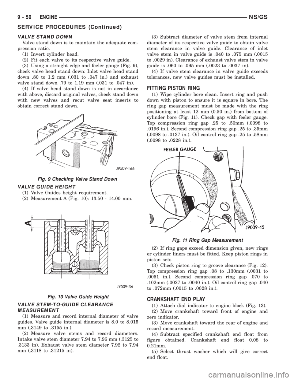
VALVE STAND DOWN
Valve stand down is to maintain the adequate com-
pression ratio.
(1) Invert cylinder head.
(2) Fit each valve to its respective valve guide.
(3) Using a straight edge and feeler gauge (Fig. 9),
check valve head stand down: Inlet valve head stand
down .80 to 1.2 mm (.031 to .047 in.) and exhaust
valve stand down .79 to 1.19 mm (.031 to .047 in).
(4) If valve head stand down is not in accordance
with above, discard original valves, check stand down
with new valves and recut valve seat inserts to
obtain correct stand down.
VALVE GUIDE HEIGHT
(1) Valve Guides height requirement.
(2) Measurement A (Fig. 10): 13.50 - 14.00 mm.
VALVE STEM-TO-GUIDE CLEARANCE
MEASUREMENT
(1) Measure and record internal diameter of valve
guides. Valve guide internal diameter is 8.0 to 8.015
mm (.3149 to .3155 in.).
(2) Measure valve stems and record diameters.
Intake valve stem diameter 7.94 to 7.96 mm (.3125 to
.3133 in). Exhaust valve stem diameter 7.92 to 7.94
mm (.3118 to .31215 in).(3) Subtract diameter of valve stem from internal
diameter of its respective valve guide to obtain valve
stem clearance in valve guide. Clearance of inlet
valve stem in valve guide is .040 to .075 mm (.0015
to .0029 in). Clearance of exhaust valve stem in valve
guide is .060 to .095 mm (.0023 to .0037 in).
(4) If valve stem clearance in valve guide exceeds
tolerances, new valve guides must be installed.
FITTING PISTON RING
(1) Wipe cylinder bore clean. Insert ring and push
down with piston to ensure it is square in bore. The
ring gap measurement must be made with the ring
positioning at least 12 mm (0.50 in.) from bottom of
cylinder bore (Fig. 11). Check gap with feeler gauge.
Top compression ring gap .25 to .50mm (.0098 to
.0196 in.). Second compression ring gap .25 to .35mm
(.0098 to .0137 in.). Oil control ring gap .25 to .58mm
(.0098 to .0228 in.).
(2) If ring gaps exceed dimension given, new rings
or cylinder liners must be fitted. Keep piston rings in
piston sets.
(3) Check piston ring to groove clearance (Fig. 12).
Top compression ring gap .08 to .130mm (.0031 to
.0051 in.). Second compression ring gap .070 to
.102mm (.0027 to .0040 in.). Oil control ring gap .040
to .072mm (.0015 to .0028 in.).
CRANKSHAFT END PLAY
(1) Attach dial indicator to engine block (Fig. 13).
(2) Move crankshaft toward front of engine and
zero indicator.
(3) Move crankshaft toward the rear of engine and
record measurement.
(4) Subtract specified crankshaft end float from
figure obtained. Crankshaft end float 0.08 to
0.21mm.
(5) Select thrust washer which will give correct
end float.
Fig. 9 Checking Valve Stand Down
Fig. 10 Valve Guide Height
Fig. 11 Ring Gap Measurement
9 - 50 ENGINENS/GS
SERVICE PROCEDURES (Continued)