compression ratio CHRYSLER VOYAGER 1996 Owner's Manual
[x] Cancel search | Manufacturer: CHRYSLER, Model Year: 1996, Model line: VOYAGER, Model: CHRYSLER VOYAGER 1996Pages: 1938, PDF Size: 55.84 MB
Page 1249 of 1938
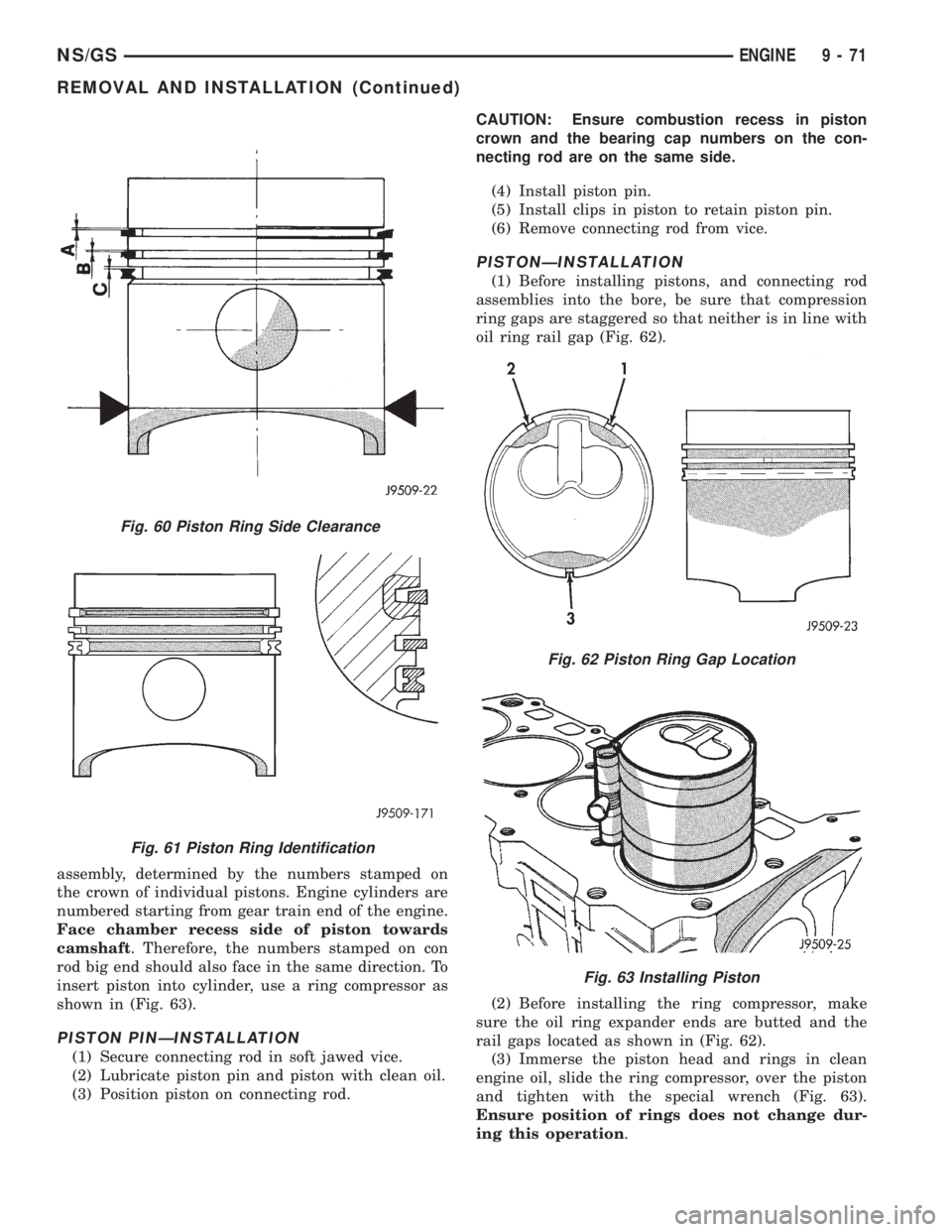
assembly, determined by the numbers stamped on
the crown of individual pistons. Engine cylinders are
numbered starting from gear train end of the engine.
Face chamber recess side of piston towards
camshaft. Therefore, the numbers stamped on con
rod big end should also face in the same direction. To
insert piston into cylinder, use a ring compressor as
shown in (Fig. 63).
PISTON PINÐINSTALLATION
(1) Secure connecting rod in soft jawed vice.
(2) Lubricate piston pin and piston with clean oil.
(3) Position piston on connecting rod.CAUTION: Ensure combustion recess in piston
crown and the bearing cap numbers on the con-
necting rod are on the same side.
(4) Install piston pin.
(5) Install clips in piston to retain piston pin.
(6) Remove connecting rod from vice.
PISTONÐINSTALLATION
(1) Before installing pistons, and connecting rod
assemblies into the bore, be sure that compression
ring gaps are staggered so that neither is in line with
oil ring rail gap (Fig. 62).
(2) Before installing the ring compressor, make
sure the oil ring expander ends are butted and the
rail gaps located as shown in (Fig. 62).
(3) Immerse the piston head and rings in clean
engine oil, slide the ring compressor, over the piston
and tighten with the special wrench (Fig. 63).
Ensure position of rings does not change dur-
ing this operation.
Fig. 60 Piston Ring Side Clearance
Fig. 61 Piston Ring Identification
Fig. 62 Piston Ring Gap Location
Fig. 63 Installing Piston
NS/GSENGINE 9 - 71
REMOVAL AND INSTALLATION (Continued)
Page 1256 of 1938
(3) If internal diameter of original bearing is being
checked and figures are not within specifications,
new bearings must be used.
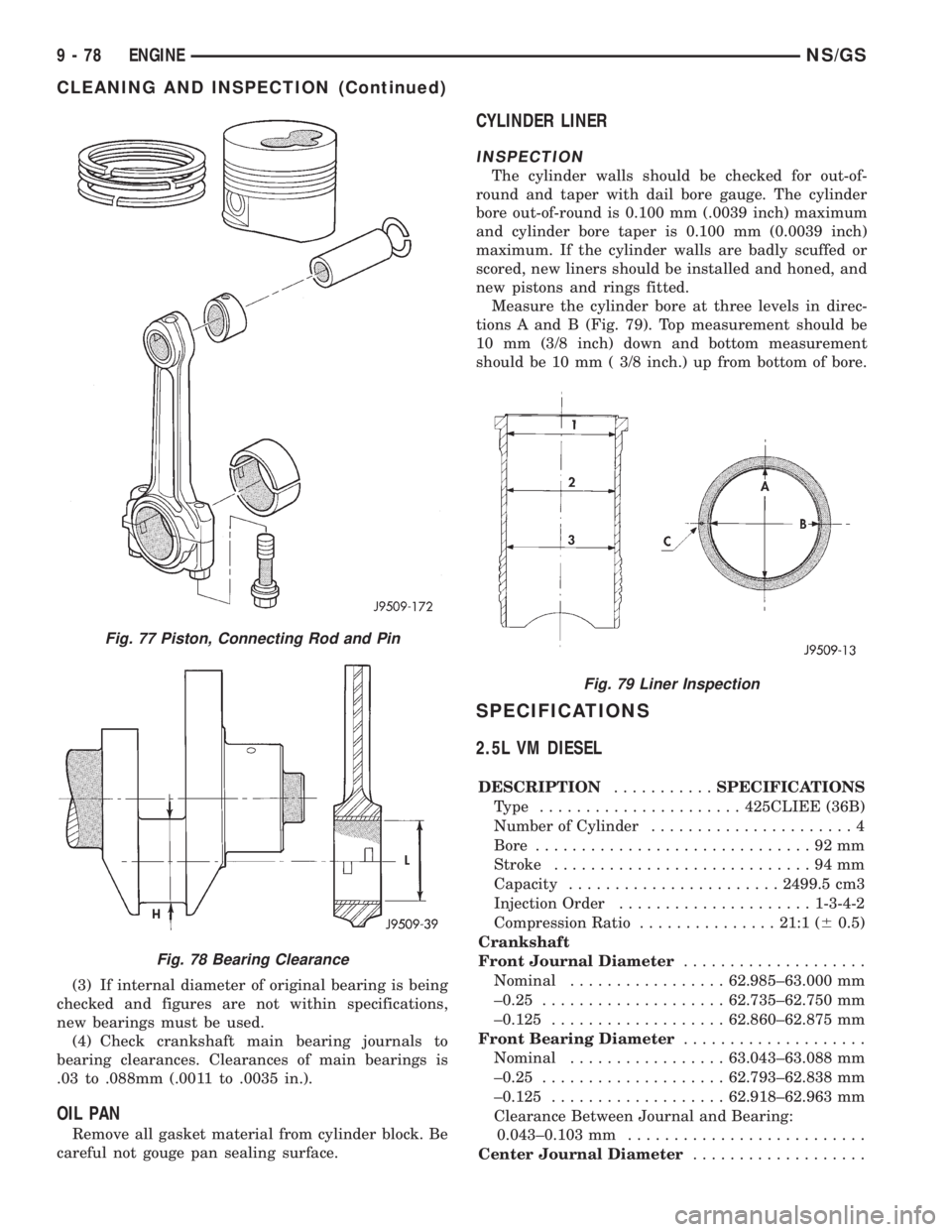
(4) Check crankshaft main bearing journals to
bearing clearances. Clearances of main bearings is
.03 to .088mm (.0011 to .0035 in.).
OIL PAN
Remove all gasket material from cylinder block. Be
careful not gouge pan sealing surface.
CYLINDER LINER
INSPECTION
The cylinder walls should be checked for out-of-
round and taper with dail bore gauge. The cylinder
bore out-of-round is 0.100 mm (.0039 inch) maximum
and cylinder bore taper is 0.100 mm (0.0039 inch)
maximum. If the cylinder walls are badly scuffed or
scored, new liners should be installed and honed, and
new pistons and rings fitted.
Measure the cylinder bore at three levels in direc-
tions A and B (Fig. 79). Top measurement should be
10 mm (3/8 inch) down and bottom measurement
should be 10 mm ( 3/8 inch.) up from bottom of bore.
SPECIFICATIONS
2.5L VM DIESEL
DESCRIPTION...........SPECIFICATIONS
Type ......................425CLIEE (36B)
Number of Cylinder......................4
Bore..............................92mm
Stroke............................94mm
Capacity.......................2499.5 cm3
Injection Order.....................1-3-4-2
Compression Ratio...............21:1 (60.5)
Crankshaft
Front Journal Diameter....................
Nominal.................62.985±63.000 mm
±0.25....................62.735±62.750 mm
±0.125...................62.860±62.875 mm
Front Bearing Diameter....................
Nominal.................63.043±63.088 mm
±0.25....................62.793±62.838 mm
±0.125...................62.918±62.963 mm
Clearance Between Journal and Bearing:
0.043±0.103 mm..........................
Center Journal Diameter...................
Fig. 77 Piston, Connecting Rod and Pin
Fig. 78 Bearing Clearance
Fig. 79 Liner Inspection
9 - 78 ENGINENS/GS
CLEANING AND INSPECTION (Continued)
Page 1339 of 1938
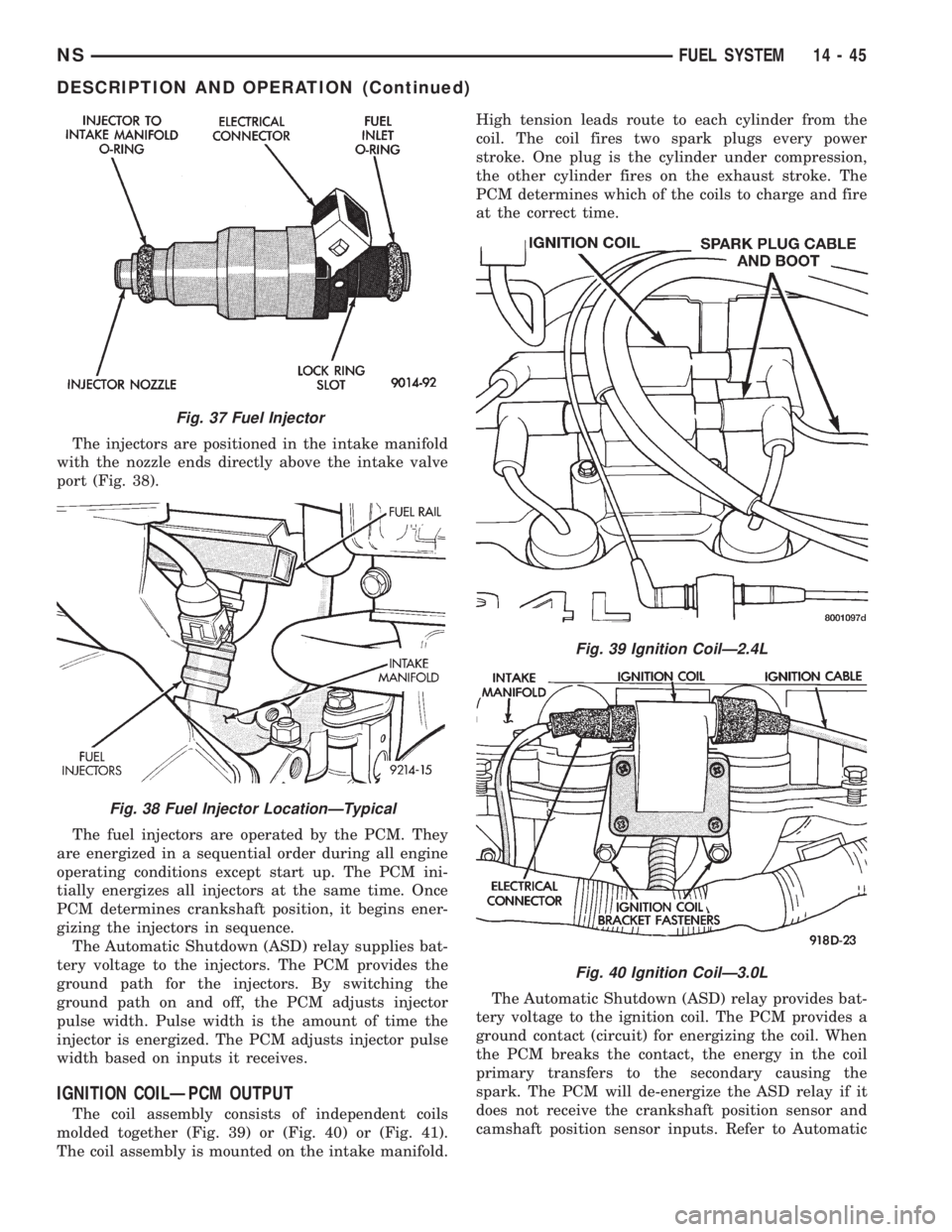
The injectors are positioned in the intake manifold
with the nozzle ends directly above the intake valve
port (Fig. 38).
The fuel injectors are operated by the PCM. They
are energized in a sequential order during all engine
operating conditions except start up. The PCM ini-
tially energizes all injectors at the same time. Once
PCM determines crankshaft position, it begins ener-
gizing the injectors in sequence.
The Automatic Shutdown (ASD) relay supplies bat-
tery voltage to the injectors. The PCM provides the
ground path for the injectors. By switching the
ground path on and off, the PCM adjusts injector
pulse width. Pulse width is the amount of time the
injector is energized. The PCM adjusts injector pulse
width based on inputs it receives.
IGNITION COILÐPCM OUTPUT
The coil assembly consists of independent coils
molded together (Fig. 39) or (Fig. 40) or (Fig. 41).
The coil assembly is mounted on the intake manifold.High tension leads route to each cylinder from the
coil. The coil fires two spark plugs every power
stroke. One plug is the cylinder under compression,
the other cylinder fires on the exhaust stroke. The
PCM determines which of the coils to charge and fire
at the correct time.
The Automatic Shutdown (ASD) relay provides bat-
tery voltage to the ignition coil. The PCM provides a
ground contact (circuit) for energizing the coil. When
the PCM breaks the contact, the energy in the coil
primary transfers to the secondary causing the
spark. The PCM will de-energize the ASD relay if it
does not receive the crankshaft position sensor and
camshaft position sensor inputs. Refer to Automatic
Fig. 37 Fuel Injector
Fig. 38 Fuel Injector LocationÐTypical
Fig. 39 Ignition CoilÐ2.4L
Fig. 40 Ignition CoilÐ3.0L
NSFUEL SYSTEM 14 - 45
DESCRIPTION AND OPERATION (Continued)
Page 1374 of 1938
Actual electric fuel timing (amount of advance) is
accomplished by the fuel timing solenoid mounted to
the bottom of the injection pump (Fig. 5). Fuel timing
will be adjusted by the PCM, which controls the fuel
timing solenoid.
An overflow valve is attached into the fuel return
line at the rear of the fuel injection pump (Fig. 4).
This valve serves two purposes. One is to ensure that
a certain amount of residual pressure is maintained
within the pump when the engine is switched off.
This will prevent the fuel timing mechanism within
the injection pump from returning to its zero posi-
tion. The other purpose is to allow excess fuel to be
returned to the fuel tank through the fuel return
line. The pressure values within this valve are preset
and can not be adjusted.
The fuel injection pump supplies high±pressure
fuel of approximately 45,000 kPa (6526 psi) to each
injector in precise metered amounts at the correct
time.
For mechanical injection pump timing, refer to
Fuel Injection Pump Timing in the Service Proce-
dures section of this group.
FUEL INJECTORS
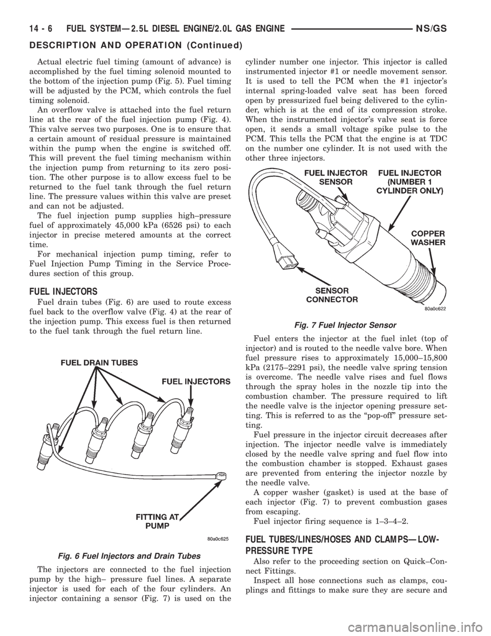
Fuel drain tubes (Fig. 6) are used to route excess
fuel back to the overflow valve (Fig. 4) at the rear of
the injection pump. This excess fuel is then returned
to the fuel tank through the fuel return line.
The injectors are connected to the fuel injection
pump by the high± pressure fuel lines. A separate
injector is used for each of the four cylinders. An
injector containing a sensor (Fig. 7) is used on thecylinder number one injector. This injector is called
instrumented injector #1 or needle movement sensor.
It is used to tell the PCM when the #1 injector's
internal spring-loaded valve seat has been forced
open by pressurized fuel being delivered to the cylin-
der, which is at the end of its compression stroke.
When the instrumented injector's valve seat is force
open, it sends a small voltage spike pulse to the
PCM. This tells the PCM that the engine is at TDC
on the number one cylinder. It is not used with the
other three injectors.
Fuel enters the injector at the fuel inlet (top of
injector) and is routed to the needle valve bore. When
fuel pressure rises to approximately 15,000±15,800
kPa (2175±2291 psi), the needle valve spring tension
is overcome. The needle valve rises and fuel flows
through the spray holes in the nozzle tip into the
combustion chamber. The pressure required to lift
the needle valve is the injector opening pressure set-
ting. This is referred to as the ªpop-offº pressure set-
ting.
Fuel pressure in the injector circuit decreases after
injection. The injector needle valve is immediately
closed by the needle valve spring and fuel flow into
the combustion chamber is stopped. Exhaust gases
are prevented from entering the injector nozzle by
the needle valve.
A copper washer (gasket) is used at the base of
each injector (Fig. 7) to prevent combustion gases
from escaping.
Fuel injector firing sequence is 1±3±4±2.
FUEL TUBES/LINES/HOSES AND CLAMPSÐLOW-
PRESSURE TYPE
Also refer to the proceeding section on Quick±Con-
nect Fittings.
Inspect all hose connections such as clamps, cou-
plings and fittings to make sure they are secure andFig. 6 Fuel Injectors and Drain Tubes
Fig. 7 Fuel Injector Sensor
14 - 6 FUEL SYSTEMÐ2.5L DIESEL ENGINE/2.0L GAS ENGINENS/GS
DESCRIPTION AND OPERATION (Continued)
Page 1861 of 1938
CAUTION: Do not damage the evaporator insulation
liner during installation.
(3) Carefully install the evaporator and expansion
valve straight into the unit. Do not scratch the seal-
ing surfaces with the plumbing extension tube pilots.
(4) Determine the amount of old refrigerant oil
drained from the evaporator. Add this amount (of
clean refrigerant oil) back into the system.
(5) Carefully align the expansion valve onto the
pilot tubes of the plumbing extension (do not scratch
the sealing surface). Install the bolt through the
plumbing plate into the unit sealing plate. Tighten
bolts to 2363 N´m (200630 inch pounds) torque.
(6) Install evaporator cover and blower scroll.
(7) Install quarter trim panel, evacuate/charge sys-
tem, and perform the performance test.
REAR AIR CONDITIONING LINES
WARNING: THE REFRIGERATION SYSTEM MUST
BE COMPLETELY EMPTY BEFORE PROCEEDING
WITH THIS OPERATION.
REMOVAL
(1) Hoist vehicle
(2) Remove compression fittings to the suction and
liquid lines located on the right, outboard side of the
underbody, rearward of the front crossmember. (Fig.
2)
(3) remove (1) bolt securing a/c lines to block
located on the right, outboard side of the underbody,
rearward of the rear wheel and tire. (Fig. 5)
(4) Remove (3) straps securing underbody lines.
(Fig. 1)
(5) Separate and remove a/c lines from vehicle.
INSTALLATION
(1) Before installation, replace all O-rings and gas-
kets. Coat all sealing surfaces with approved wax-
free refrigerant oil. Then, reverse the above
procedures.
(2) Evacuate and recharge system.
REAR HEATER A/C AIR OUTLETS
REMOVAL
Separate barrel from bezel by pulling outward.
INSTALLATION
For installation, push the outlet firmly into the
opening until it locks into place.
REAR HEATER-A/C AUXILIARY CONDENSER
If vehicle is equipped with a 3.3L or 3.8L engine
with rear heater and air conditioning, it will be
equipped with an auxiliary condenser. The auxiliarycondenser is mounted on the primary condenser in
front of the radiator. Both condenser must be
removed as an assembly and then separated.
WARNING: THE REFRIGERATION SYSTEM MUST
BE COMPLETELY EMPTY BEFORE PROCEEDING
WITH THIS OPERATION.
NOTE: Special effort must be used to keep all
R-134a system components moisture-free. Moisture
in the oil is very difficult to remove and will cause a
reliability problem with the compressor.
The condenser assembly must first be removed
from vehicle. Refer to CONDENSER ASSEMBLY
removal and installation in this section for service
procedures.
REMOVAL
(1) After condenser assembly removal, place on
bench for disassembly.
(2) Remove (1) bolt to liquid line on auxiliary con-
denser.
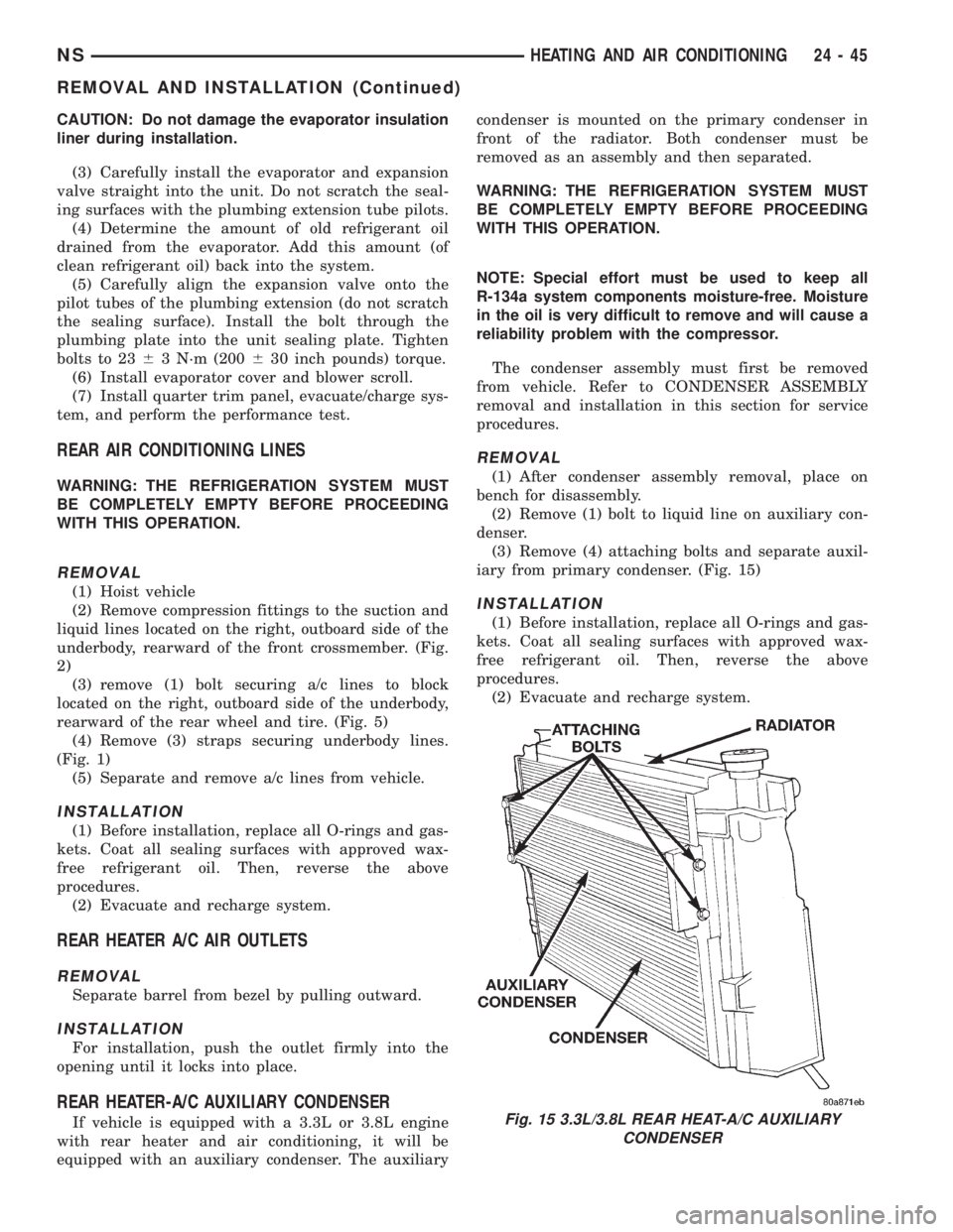
(3) Remove (4) attaching bolts and separate auxil-
iary from primary condenser. (Fig. 15)
INSTALLATION
(1) Before installation, replace all O-rings and gas-
kets. Coat all sealing surfaces with approved wax-
free refrigerant oil. Then, reverse the above
procedures.
(2) Evacuate and recharge system.
Fig. 15 3.3L/3.8L REAR HEAT-A/C AUXILIARY
CONDENSER
NSHEATING AND AIR CONDITIONING 24 - 45
REMOVAL AND INSTALLATION (Continued)
Page 1915 of 1938
components now have input (rationality) and output
(functionality) checks. Previously, a component like
the Throttle Position sensor (TPS) was checked by
the PCM for an open or shorted circuit. If one of
these conditions occurred, a DTC was set. Now there
is a check to ensure that the component is working.
This is done by watching for a TPS indication of a
greater or lesser throttle opening than MAP and
engine rpm indicate. In the case of the TPS, if engine
vacuum is high and engine rpm is 1600 or greater
and the TPS indicates a large throttle opening, a
DTC will be set. The same applies to low vacuum
and 1600 rpm.
Any component that has an associated limp in will
set a fault after 1 trip with the malfunction present.
Refer to the Diagnostic Trouble Codes Description
Charts in this section and the appropriate Power-
train Diagnostic Procedure Manual for diagnostic
procedures.
NON-MONITORED CIRCUITS
The PCM does not monitor all circuits, systems
and conditions that could have malfunctions causing
driveability problems. However, problems with these
systems may cause the PCM to store diagnostic trou-
ble codes for other systems or components. For exam-
ple, a fuel pressure problem will not register a fault
directly, but could cause a rich/lean condition or mis-
fire. This could cause the PCM to store an oxygen
sensor or misfire diagnostic trouble code.
The major non-monitored circuits are listed below
along with examples of failures modes that do not
directly cause the PCM to set a DTC, but for a sys-
tem that is monitored.
FUEL PRESSURE
The fuel pressure regulator controls fuel system
pressure. The PCM cannot detect a clogged fuel
pump inlet filter, clogged in-line fuel filter, or a
pinched fuel supply or return line. However, these
could result in a rich or lean condition causing the
PCM to store an oxygen sensor or fuel system diag-
nostic trouble code.
SECONDARY IGNITION CIRCUIT
The PCM cannot detect an inoperative ignition coil,
fouled or worn spark plugs, ignition cross firing, or
open spark plug cables.
CYLINDER COMPRESSION
The PCM cannot detect uneven, low, or high engine
cylinder compression.
EXHAUST SYSTEM
The PCM cannot detect a plugged, restricted or
leaking exhaust system. It may set a EGR or Fuel
system fault or O2S.
FUEL INJECTOR MECHANICAL
MALFUNCTIONS
The PCM cannot determine if a fuel injector is
clogged, the needle is sticking or if the wrong injector
is installed. However, these could result in a rich or
lean condition causing the PCM to store a diagnostic
trouble code for either misfire, an oxygen sensor, or
the fuel system.
EXCESSIVE OIL CONSUMPTION
Although the PCM monitors engine exhaust oxygen
content when the system is in closed loop, it cannot
determine excessive oil consumption.
THROTTLE BODY AIR FLOW
The PCM cannot detect a clogged or restricted air
cleaner inlet or filter element.
VACUUM ASSIST
The PCM cannot detect leaks or restrictions in the
vacuum circuits of vacuum assisted engine control
system devices. However, these could cause the PCM
to store a MAP sensor diagnostic trouble code and
cause a high idle condition.
PCM SYSTEM GROUND
The PCM cannot determine a poor system ground.
However, one or more diagnostic trouble codes may
be generated as a result of this condition. The mod-
ule should be mounted to the body at all times, also
during diagnostic.
PCM CONNECTOR ENGAGEMENT
The PCM may not be able to determine spread or
damaged connector pins. However, it might store
diagnostic trouble codes as a result of spread connec-
tor pins.
HIGH AND LOW LIMITS
The PCM compares input signal voltages from each
input device with established high and low limits for
the device. If the input voltage is not within limits
and other criteria are met, the PCM stores a diagnos-
tic trouble code in memory. Other diagnostic trouble
code criteria might include engine RPM limits or
input voltages from other sensors or switches that
must be present before verifying a diagnostic trouble
code condition.
NSEMISSION CONTROL SYSTEMS 25 - 11
DESCRIPTION AND OPERATION (Continued)
Page 1929 of 1938
EMISSION CONTROL SYSTEM
CONTENTS
page page
EMISSION CONTROL SYSTEMÐ
2.0L ENGINE.......................... 9
EXHAUST EMISSION CONTROLSÐ
2.5L DIESEL ENGINE................... 5ON-BOARD DIAGNOSTICSÐ
2.5L DIESEL ENGINE................... 1
ON-BOARD DIAGNOSTICSÐ2.5L DIESEL ENGINE
INDEX
page page
GENERAL INFORMATION
SYSTEM DESCRIPTIONÐ
2.5L DIESEL ENGINE................... 1DESCRIPTION AND OPERATION
DIAGNOSTIC TROUBLE CODES............ 2
GENERAL INFORMATION
SYSTEM DESCRIPTIONÐ2.5L DIESEL ENGINE
The 2.5L diesel Powertrain Control Module (PCM)
monitors and controls many different circuits in the
fuel injection pump and engine systems. If the PCM
senses a problem with a monitored circuit that indi-
cates an actual problem, a Diagnostic Trouble Code
(DTC) will be stored in the PCM's memory, and even-
tually will illuminate the Diesel Glow Plug lamp con-
stantly while the key is on. If the problem is
repaired, or is intermittent, the PCM will erase the
DTC after 40 warm-up cycles. A warm-up cycle con-
sists of starting the vehicle when the engine is cold,
then the engine to warms up to a certain tempera-
ture, and finally, the engine temperature falls to a
normal operating temperature, then the key is
turned off.
Certain criteria must be met for a DTC to be
entered into PCM memory. The criteria may be a
specific range of engine rpm, engine or fuel tempera-
ture and/or input voltage to the PCM. A DTC indi-
cates that the PCM has identified an abnormal
signal in a circuit or the system. A DTC may indicate
the result of a failure, but never identify the failed
component directly.
There are several operating conditions that the
PCM does not monitor and set a DTC for. Refer to
the following Monitored Circuits and Non±Monitored
Circuits in this section.
MONITORED CIRCUITS
The PCM can detect certain problems in the elec-
trical system.
Open or Shorted Circuit± The PCM can deter-
mine if sensor output (which is the input to PCM) is
within proper range. It also determines if the circuit
is open or shorted.
Output Device Current Flow± The PCM senses
whether the output devices are electrically connected.
If there is a problem with the circuit, the PCM
senses whether the circuit is open, shorted to ground
(±), or shorted to (+) voltage.
NON±MONITORED CIRCUITS
The PCM does not monitor the following circuits,
systems or conditions that could have malfunctions
that result in driveability problems. A DTC will not
be displayed for these conditions.
Fuel Pressure:Fuel pressure is controlled by the
fuel injection pump. The PCM cannot detect prob-
lems in this component.
Cylinder Compression:The PCM cannot detect
uneven, low, or high engine cylinder compression.
Exhaust System:The PCM cannot detect a
plugged, restricted or leaking exhaust system.
Fuel Injector Malfunctions:The PCM cannot
determine if the fuel injector is clogged, or the wrong
injector is installed. The fuel injectors on the diesel
engine arenot controlledby the PCM, although a
NS/GSEMISSION CONTROL SYSTEM 25 - 1