fuse diagram CHRYSLER VOYAGER 1996 User Guide
[x] Cancel search | Manufacturer: CHRYSLER, Model Year: 1996, Model line: VOYAGER, Model: CHRYSLER VOYAGER 1996Pages: 1938, PDF Size: 55.84 MB
Page 443 of 1938
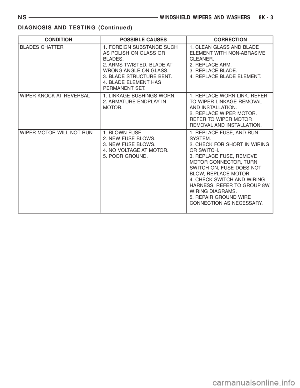
CONDITION POSSIBLE CAUSES CORRECTION
BLADES CHATTER 1. FOREIGN SUBSTANCE SUCH
AS POLISH ON GLASS OR
BLADES.
2. ARMS TWISTED, BLADE AT
WRONG ANGLE ON GLASS.
3. BLADE STRUCTURE BENT.
4. BLADE ELEMENT HAS
PERMANENT SET.1. CLEAN GLASS AND BLADE
ELEMENT WITH NON-ABRASIVE
CLEANER.
2. REPLACE ARM.
3. REPLACE BLADE.
4. REPLACE BLADE ELEMENT.
WIPER KNOCK AT REVERSAL 1. LINKAGE BUSHINGS WORN.
2. ARMATURE ENDPLAY IN
MOTOR.1. REPLACE WORN LINK. REFER
TO WIPER LINKAGE REMOVAL
AND INSTALLATION.
2. REPLACE WIPER MOTOR.
REFER TO WIPER MOTOR
REMOVAL AND INSTALLATION.
WIPER MOTOR WILL NOT RUN 1. BLOWN FUSE.
2. NEW FUSE BLOWS.
3. NEW FUSE BLOWS.
4. NO VOLTAGE AT MOTOR.
5. POOR GROUND.1. REPLACE FUSE, AND RUN
SYSTEM.
2. CHECK FOR SHORT IN WIRING
OR SWITCH.
3. REPLACE FUSE, REMOVE
MOTOR CONNECTOR, TURN
SWITCH ON, FUSE DOES NOT
BLOW, REPLACE MOTOR.
4. CHECK SWITCH AND WIRING
HARNESS. REFER TO GROUP 8W,
WIRING DIAGRAMS.
5. REPAIR GROUND WIRE
CONNECTION AS NECESSARY.
NSWINDSHIELD WIPERS AND WASHERS 8K - 3
DIAGNOSIS AND TESTING (Continued)
Page 453 of 1938

LAMPS
CONTENTS
page page
BULB APPLICATION...................... 25
EXTERIOR LAMP BULB SERVICE............ 9
EXTERIOR LAMP SERVICE................. 14HEADLAMP ALIGNMENT................... 5
INTERIOR LAMPS........................ 18
LAMP DIAGNOSIS........................ 1
LAMP DIAGNOSIS
INDEX
page page
GENERAL INFORMATION
ELECTRONIC DAYTIME RUNNING LIGHT (DRL).1
GENERAL INFORMATION.................. 1SAFETY PRECAUTIONS................... 1
DIAGNOSIS AND TESTING
DIAGNOSTIC PROCEDURES................ 2
GENERAL INFORMATION
GENERAL INFORMATION
NS vehicles use lighting on the interior and exte-
rior of the vehicle for illuminating and indicating
purposes. Lighting circuits are protected by fuses.
Lighting circuits require an overload protected power
source, on/off device, lamps and body ground to oper-
ate properly. Plastic lamps require a wire in the har-
ness to supply body ground to the lamp socket.
Replace sockets and bulbs that are corroded.
Some of the interior and exterior lighting functions
are governed by the body controller. The headlamp,
dome, and the door ajar switches provide signals to
the body controller. The body controller in turn acti-
vates relay(s) in order to provide either a ground or
feed line to the appropriate lamp(s).
Wire connectors can make intermittent contact or
become corroded. Before coupling wire connectors,
inspect the terminals inside the connector. Male ter-
minals should not be bent or disengaged from the
insulator. Female terminals should not be sprung
open or disengaged from the insulator. Bent and
sprung terminals can be repaired using needle nose
pliers and pick tool. Corroded terminals appear
chalky or green. Corroded terminals should be
replaced to avoid recurrence of the problem symp-
toms.
Begin electrical system failure diagnosis by testing
related fuses in the fuse block and power distribution
center. Verify that bulbs are in good condition andtest continuity of the circuit ground. Refer to Group
8W, Wiring Diagrams, for component location and cir-
cuit information.SAFETY PRECAUTIONS
WARNING: EYE PROTECTION SHOULD BE USED
WHEN SERVICING GLASS COMPONENTS. PER-
SONAL INJURY CAN RESULT.
CAUTION: Do not touch the glass of halogen bulbs
with fingers or other possibly oily surface, reduced
bulb life will result.
Do not use bulbs with higher candle power than
indicated in the Bulb Application table at the end of
this group. Damage to lamp and/or Daytime Run-
ning Lamp Module can result.
Do not use fuses, circuit breakers or relays hav-
ing greater amperage value than indicated on the
fuse panel or in the Owners Manual.
When it is necessary to remove components to ser-
vice another, it should not be necessary to apply
excessive force or bend a component to remove it.
Before damaging a trim component, verify hidden
fasteners or captured edges are not holding the com-
ponent in place.
ELECTRONIC DAYTIME RUNNING LIGHT (DRL)
The Combination Flasher/DRL is a module provid-
ing turn signal, hazard warning, and daytime run-
NSLAMPS 8L - 1
Page 479 of 1938

LAMPS
CONTENTS
page page
BULB APPLICATION..................... 17
HEADLAMP ALIGNMENT.................. 5
LAMP BULB SERVICE.................... 8LAMP DIAGNOSIS....................... 1
LAMP SERVICE........................ 13
LAMP DIAGNOSIS
INDEX
page page
GENERAL INFORMATION
HEADLAMP LEVELING MOTOR............. 2
INTRODUCTION........................ 1SAFETY PRECAUTIONS.................. 1
DIAGNOSIS AND TESTING
DIAGNOSTIC PROCEDURES.............. 2
GENERAL INFORMATION
INTRODUCTION
GS vehicles use lighting on the interior and exte-
rior of the vehicle for illuminating and indicating
purposes. Lighting circuits are protected by fuses.
Lighting circuits require an overload protected power
source, on/off device, lamps and body ground to oper-
ate properly. Plastic lamps require a wire in the har-
ness to supply body ground to the lamp socket.
Replace sockets and bulbs that are corroded.
Some of the interior and exterior lighting functions
are governed by the body controller. The headlamp,
dome, and the door ajar switches provide signals to
the body controller. The body controller in turn acti-
vates relay(s) in order to provide either a ground or
feed line to the appropriate lamp(s).
Wire connectors can make intermittent contact or
become corroded. Before coupling wire connectors,
inspect the terminals inside the connector. Male ter-
minals should not be bent or disengaged from the
insulator. Female terminals should not be sprung
open or disengaged from the insulator. Bent and
sprung terminals can be repaired using needle nose
pliers and pick tool. Corroded terminals appear
chalky or green. Corroded terminals should be
replaced to avoid recurrence of the problem symp-
toms.Begin electrical system failure diagnosis by testing
related fuses in the fuse block and power distribution
center. Verify that bulbs are in good condition and
test continuity of the circuit ground. Refer to Group
8W, Wiring Diagrams, for component location and cir-
cuit information.
SAFETY PRECAUTIONS
WARNING: EYE PROTECTION SHOULD BE USED
WHEN SERVICING GLASS COMPONENTS. PER-
SONAL INJURY CAN RESULT.
CAUTION: Do not touch the glass of halogen bulbs
with fingers or other possibly oily surface, reduced
bulb life will result.
Do not use bulbs with higher candle power than
indicated in the Bulb Application table at the end of
this group. Damage to lamp and/or Daytime Run-
ning Lamp Module can result.
Do not use fuses, circuit breakers or relays hav-
ing greater amperage value than indicated on the
fuse panel or in the Owners Manual.
When it is necessary to remove components to ser-
vice another, it should not be necessary to apply
excessive force or bend a component to remove it.
Before damaging a trim component, verify hidden
fasteners or captured edges are not holding the com-
ponent in place.
NS/GSLAMPS 8L - 1
Page 505 of 1938
ELECTRICALLY HEATED SYSTEMS
CONTENTS
page page
DESCRIPTION AND OPERATION
HVAC MOUNTED SWITCH................. 1
INTRODUCTION......................... 1
DIAGNOSIS AND TESTING
GRID LINE TEST......................... 2SYSTEM TEST.......................... 2
SERVICE PROCEDURES
GRID LINE AND TERMINAL REPAIR......... 3
DESCRIPTION AND OPERATION
INTRODUCTION
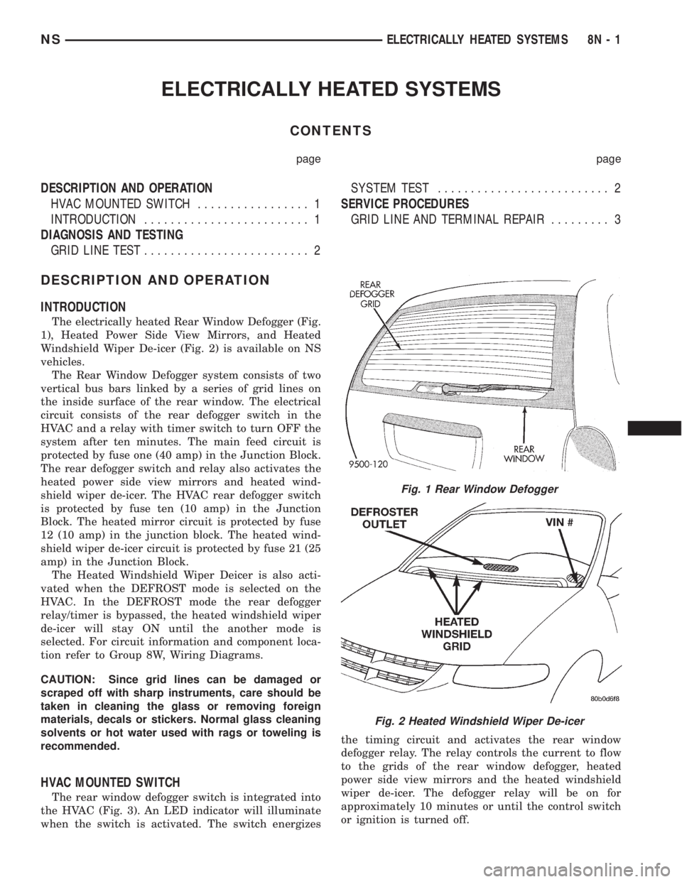
The electrically heated Rear Window Defogger (Fig.
1), Heated Power Side View Mirrors, and Heated
Windshield Wiper De-icer (Fig. 2) is available on NS
vehicles.
The Rear Window Defogger system consists of two
vertical bus bars linked by a series of grid lines on
the inside surface of the rear window. The electrical
circuit consists of the rear defogger switch in the
HVAC and a relay with timer switch to turn OFF the
system after ten minutes. The main feed circuit is
protected by fuse one (40 amp) in the Junction Block.
The rear defogger switch and relay also activates the
heated power side view mirrors and heated wind-
shield wiper de-icer. The HVAC rear defogger switch
is protected by fuse ten (10 amp) in the Junction
Block. The heated mirror circuit is protected by fuse
12 (10 amp) in the junction block. The heated wind-
shield wiper de-icer circuit is protected by fuse 21 (25
amp) in the Junction Block.
The Heated Windshield Wiper Deicer is also acti-
vated when the DEFROST mode is selected on the
HVAC. In the DEFROST mode the rear defogger
relay/timer is bypassed, the heated windshield wiper
de-icer will stay ON until the another mode is
selected. For circuit information and component loca-
tion refer to Group 8W, Wiring Diagrams.
CAUTION: Since grid lines can be damaged or
scraped off with sharp instruments, care should be
taken in cleaning the glass or removing foreign
materials, decals or stickers. Normal glass cleaning
solvents or hot water used with rags or toweling is
recommended.
HVAC MOUNTED SWITCH
The rear window defogger switch is integrated into
the HVAC (Fig. 3). An LED indicator will illuminate
when the switch is activated. The switch energizesthe timing circuit and activates the rear window
defogger relay. The relay controls the current to flow
to the grids of the rear window defogger, heated
power side view mirrors and the heated windshield
wiper de-icer. The defogger relay will be on for
approximately 10 minutes or until the control switch
or ignition is turned off.
Fig. 1 Rear Window Defogger
Fig. 2 Heated Windshield Wiper De-icer
NSELECTRICALLY HEATED SYSTEMS 8N - 1
Page 506 of 1938

DIAGNOSIS AND TESTING
SYSTEM TEST
Electrically heated rear window defogger or the
heated windshield wiper deicer operation can be
checked on the vehicle in the following manner:
(1) Turn the ignition switch to the ON position.
(2) Using a ammeter on the battery, turn the rear
defogger control switch to the ON position, a distinct
increase in amperage draw should be noted.
(3) The rear window defogger or the heated wind-
shield wiper deicer operation can be checked by feel-
ing the glass. A distinct difference in temperature
between the grid lines and adjacent clear glass can
be detected in 3 to 4 minutes of operation.
(4) Using a DC voltmeter (Fig. 4) contact terminal
B with the negative lead, and terminal A with the
positive lead. The voltmeter should read 10-14 volts.
(5) Indicator light illumination means that there is
power available at the switch only and does not nec-
essarily verify system operation.
(6) If turning the defogger switch ON, no distinct
current draw on the ammeter the problem should be
isolated in the following manner:
²Confirm that ignition switch is ON.
²Ensure that the heated rear window or the
heated windshield wiper deicer feed pigtail is con-
nected to the wiring harness and that the ground
pigtail is in fact grounded.
²Ensure that the proper fuse in the Junction
Block is OK.(7) When the above steps have been completed and
the system is still inoperative, one or more of the fol-
lowing is defective:
²HVAC switch
²Rear window defogger relay in the relay bank.
²Check for loose connector or a wire pushed out
of connector.
²Rear window or the windshield grid lines (all
grid lines would have to be broken, or one of the feed
pigtails not connected to the bus bar, for no ammeter
deflection).
(8) If turning the switch ON produces severe volt-
meter deflection, the circuit should be closely checked
for a shorting condition.
(9) If the system operation has been verified but
indicator LED does not light, replace switch.
(10) For detailed wiring information, refer to
Group 8W, Wiring Diagrams.
GRID LINE TEST
The horizontal grid lines and vertical bus bar lines
printed and baked on inside surface of the window
glass makes up an electrical parallel circuit. The
electrically conductive lines are composed of a silver
ceramic material which when baked on glass
becomes bonded to the glass and is highly resistant
to abrasion. It is possible, however, that a break may
exist or occur in an individual grid line resulting in
no current flow through the line. To detect breaks in
grid lines, the following procedure is required:
(1) Turn ignition and rear window defogger control
switch ON. The indicator light should come on.
(2) Using a DC voltmeter with 0-15 volt range,
contact vertical bus bar connecting grid lines on pas-
senger side of vehicle at terminal A with negative
lead of voltmeter (Fig. 4). With positive lead of volt-
meter, contact vertical bus bar on driver side of vehi-
cle at terminal B. The voltmeter should read 10-14
volts.
Fig. 3 HVAC Rear Window Defogger Switch
Fig. 4 Grid Line Test
8N - 2 ELECTRICALLY HEATED SYSTEMSNS
DIAGNOSIS AND TESTING (Continued)
Page 521 of 1938
determine whether a valid key is in the ignition lock
cylinder.
The Smart Key transponder cannot be repaired
and, if faulty or damaged, it must be replaced.
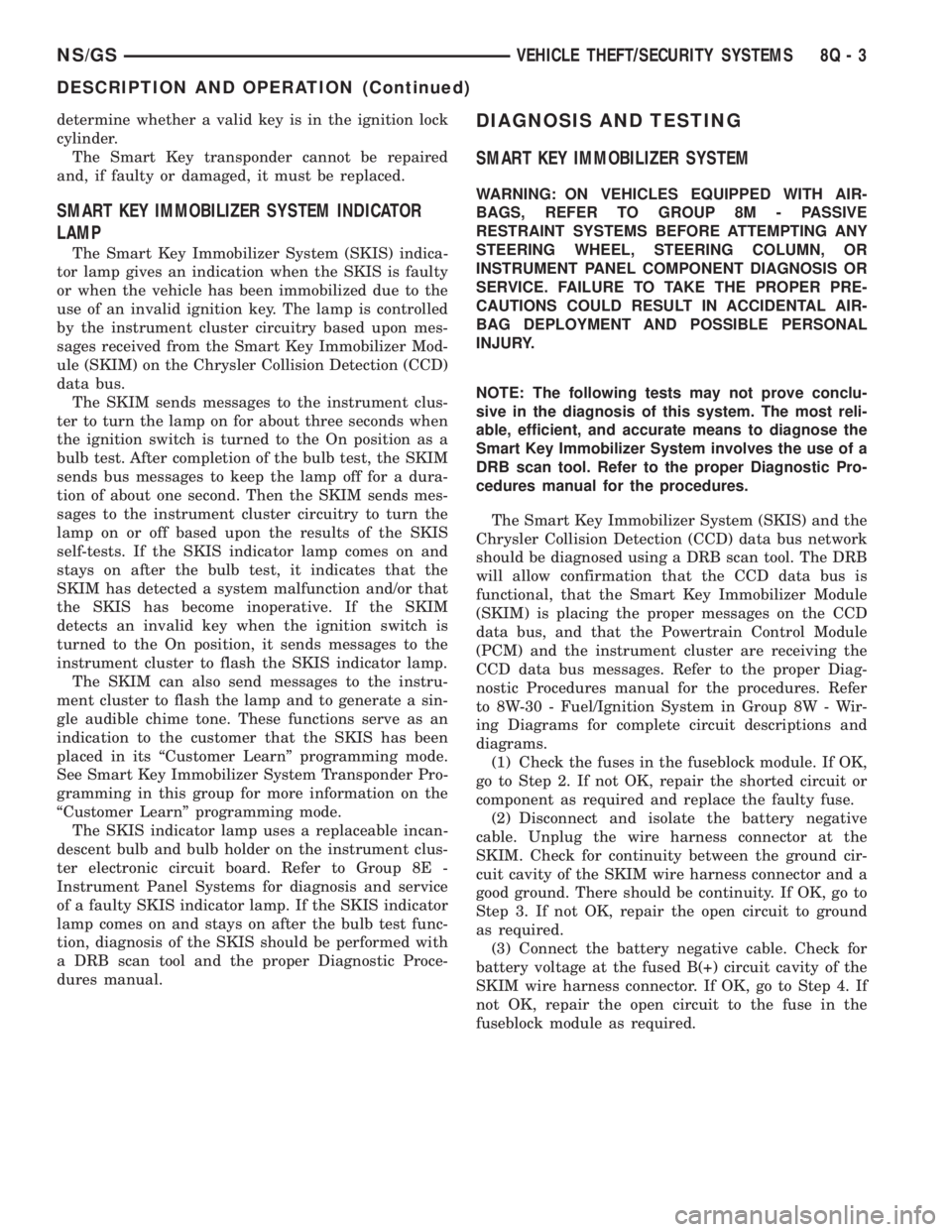
SMART KEY IMMOBILIZER SYSTEM INDICATOR
LAMP
The Smart Key Immobilizer System (SKIS) indica-
tor lamp gives an indication when the SKIS is faulty
or when the vehicle has been immobilized due to the
use of an invalid ignition key. The lamp is controlled
by the instrument cluster circuitry based upon mes-
sages received from the Smart Key Immobilizer Mod-
ule (SKIM) on the Chrysler Collision Detection (CCD)
data bus.
The SKIM sends messages to the instrument clus-
ter to turn the lamp on for about three seconds when
the ignition switch is turned to the On position as a
bulb test. After completion of the bulb test, the SKIM
sends bus messages to keep the lamp off for a dura-
tion of about one second. Then the SKIM sends mes-
sages to the instrument cluster circuitry to turn the
lamp on or off based upon the results of the SKIS
self-tests. If the SKIS indicator lamp comes on and
stays on after the bulb test, it indicates that the
SKIM has detected a system malfunction and/or that
the SKIS has become inoperative. If the SKIM
detects an invalid key when the ignition switch is
turned to the On position, it sends messages to the
instrument cluster to flash the SKIS indicator lamp.
The SKIM can also send messages to the instru-
ment cluster to flash the lamp and to generate a sin-
gle audible chime tone. These functions serve as an
indication to the customer that the SKIS has been
placed in its ªCustomer Learnº programming mode.
See Smart Key Immobilizer System Transponder Pro-
gramming in this group for more information on the
ªCustomer Learnº programming mode.
The SKIS indicator lamp uses a replaceable incan-
descent bulb and bulb holder on the instrument clus-
ter electronic circuit board. Refer to Group 8E -
Instrument Panel Systems for diagnosis and service
of a faulty SKIS indicator lamp. If the SKIS indicator
lamp comes on and stays on after the bulb test func-
tion, diagnosis of the SKIS should be performed with
a DRB scan tool and the proper Diagnostic Proce-
dures manual.
DIAGNOSIS AND TESTING
SMART KEY IMMOBILIZER SYSTEM
WARNING: ON VEHICLES EQUIPPED WITH AIR-
BAGS, REFER TO GROUP 8M - PASSIVE
RESTRAINT SYSTEMS BEFORE ATTEMPTING ANY
STEERING WHEEL, STEERING COLUMN, OR
INSTRUMENT PANEL COMPONENT DIAGNOSIS OR
SERVICE. FAILURE TO TAKE THE PROPER PRE-
CAUTIONS COULD RESULT IN ACCIDENTAL AIR-
BAG DEPLOYMENT AND POSSIBLE PERSONAL
INJURY.
NOTE: The following tests may not prove conclu-
sive in the diagnosis of this system. The most reli-
able, efficient, and accurate means to diagnose the
Smart Key Immobilizer System involves the use of a
DRB scan tool. Refer to the proper Diagnostic Pro-
cedures manual for the procedures.
The Smart Key Immobilizer System (SKIS) and the
Chrysler Collision Detection (CCD) data bus network
should be diagnosed using a DRB scan tool. The DRB
will allow confirmation that the CCD data bus is
functional, that the Smart Key Immobilizer Module
(SKIM) is placing the proper messages on the CCD
data bus, and that the Powertrain Control Module
(PCM) and the instrument cluster are receiving the
CCD data bus messages. Refer to the proper Diag-
nostic Procedures manual for the procedures. Refer
to 8W-30 - Fuel/Ignition System in Group 8W - Wir-
ing Diagrams for complete circuit descriptions and
diagrams.
(1) Check the fuses in the fuseblock module. If OK,
go to Step 2. If not OK, repair the shorted circuit or
component as required and replace the faulty fuse.
(2) Disconnect and isolate the battery negative
cable. Unplug the wire harness connector at the
SKIM. Check for continuity between the ground cir-
cuit cavity of the SKIM wire harness connector and a
good ground. There should be continuity. If OK, go to
Step 3. If not OK, repair the open circuit to ground
as required.
(3) Connect the battery negative cable. Check for
battery voltage at the fused B(+) circuit cavity of the
SKIM wire harness connector. If OK, go to Step 4. If
not OK, repair the open circuit to the fuse in the
fuseblock module as required.
NS/GSVEHICLE THEFT/SECURITY SYSTEMS 8Q - 3
DESCRIPTION AND OPERATION (Continued)
Page 527 of 1938
If motor grunts and does not move, verify that reg-
ulator is not binding.
WIRING VOLTAGE TEST
The following wiring test determines whether or
not voltage is continuous through the body harness
to switch.
(1) Remove the master power window switch and
bezel assembly from the driver door. Refer to Group
23, Body for proper procedures.
(2) Disconnect wire connector from back of power
window switch.
(3) Switch ignition ON position.
(4) Connect the clip end of a 12 volt test light to
Pin 13 in door harness connector at the window
switch. Touch the test light probe to Pin 9 and then
to Pin 11.
²If the test light illuminates, the wiring circuit
between the battery and switch is OK.
²If light does not illuminate, check the 40 amp
fuse in the Power Distribution Center or for a broken
wire.
²The power window motors are protected with
Positive Temperature Coefficient (PTC) device that
prevents motor burn out. Check Junction Block.
²Refer to Group 8W, Wiring Diagrams for circuit
information and component locations.
REMOVAL AND INSTALLATION
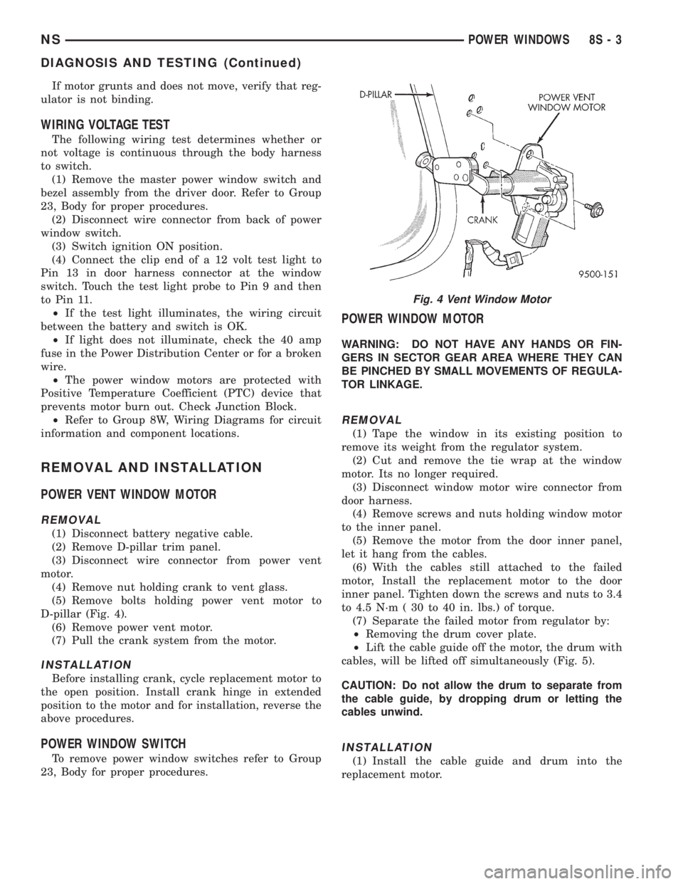
POWER VENT WINDOW MOTOR
REMOVAL
(1) Disconnect battery negative cable.
(2) Remove D-pillar trim panel.
(3) Disconnect wire connector from power vent
motor.
(4) Remove nut holding crank to vent glass.
(5) Remove bolts holding power vent motor to
D-pillar (Fig. 4).
(6) Remove power vent motor.
(7) Pull the crank system from the motor.
INSTALLATION
Before installing crank, cycle replacement motor to
the open position. Install crank hinge in extended
position to the motor and for installation, reverse the
above procedures.
POWER WINDOW SWITCH
To remove power window switches refer to Group
23, Body for proper procedures.
POWER WINDOW MOTOR
WARNING: DO NOT HAVE ANY HANDS OR FIN-
GERS IN SECTOR GEAR AREA WHERE THEY CAN
BE PINCHED BY SMALL MOVEMENTS OF REGULA-
TOR LINKAGE.
REMOVAL
(1) Tape the window in its existing position to
remove its weight from the regulator system.
(2) Cut and remove the tie wrap at the window
motor. Its no longer required.
(3) Disconnect window motor wire connector from
door harness.
(4) Remove screws and nuts holding window motor
to the inner panel.
(5) Remove the motor from the door inner panel,
let it hang from the cables.
(6) With the cables still attached to the failed
motor, Install the replacement motor to the door
inner panel. Tighten down the screws and nuts to 3.4
to 4.5 N´m ( 30 to 40 in. lbs.) of torque.
(7) Separate the failed motor from regulator by:
²Removing the drum cover plate.
²Lift the cable guide off the motor, the drum with
cables, will be lifted off simultaneously (Fig. 5).
CAUTION: Do not allow the drum to separate from
the cable guide, by dropping drum or letting the
cables unwind.
INSTALLATION
(1) Install the cable guide and drum into the
replacement motor.
Fig. 4 Vent Window Motor
NSPOWER WINDOWS 8S - 3
DIAGNOSIS AND TESTING (Continued)
Page 529 of 1938
POWER SEATS
CONTENTS
page page
MEMORY SEAT AND MIRROR SYSTEM....... 3POWER SEATS........................... 1
POWER SEATS
INDEX
page page
GENERAL INFORMATION
INTRODUCTION......................... 1
DIAGNOSIS AND TESTING
DIAGNOSTIC PROCEDURES................ 1POWER SEAT SWITCH.................... 1
SEATMOTORS .......................... 1
GENERAL INFORMATION
INTRODUCTION
Power seats can be adjusted in eight directions; up,
down, forward, back, tilt forward, or tilt rearward.
Four reversible motors and a transmission located on
the seat tracks provide the various seat movements.
The electrical circuit is protected by a 40 amp fuse in
the Power Distribution Center (PDC) and a 30 amp
circuit breaker located in the wire harness under the
driver's seat.
DIAGNOSIS AND TESTING
DIAGNOSTIC PROCEDURES
Before testing the seat functions, verify that the
battery is fully charged and the terminals cleaned
and tightened to ensure proper connections. If the
battery is not fully charged, refer to Group 8A Bat-
tery for proper testing procedures.
The following test will determine if the circuit is
complete through the body harness to the switch:
Using a voltmeter, verify the condition of the power
seat circuit breaker located under the driver's seat.
The circuit breaker also protects the passenger side
power seat track circuit. Check both sides of the cir-
cuit breaker connector for voltage, on the wire side.
²If not OK replace circuit breaker.
²If battery voltage is detected on both sides of the
circuit breaker. Refer to Seat Motor in the Diagnostic
and Testing in this section.²If seat motors test OK, refer to the Seat Switch
in the Diagnostic and Testing in this section.
²Refer to Group 8W Wiring Diagrams for wire
circuit information.
SEAT MOTORS
(1) Remove power seat switch from seat. Refer to
Group 23 Body for procedures.
(2) Disconnect wire connector.
(3) Using a voltmeter check for battery voltage at
Pin 5. Using an ohmmeter, check Pin 1 for ground.
(4) To test the seat motors, refer to (Fig. 1) and
verify proper seat responses. Using two jumper
wires, connect one to a battery supply and the other
to a ground. Connect the other ends to the seat wire
harness connector as described in (Fig. 1). If any
motor fails to operate, check wire connectors to the
motor. If not OK, repair as necessary. If OK, replace
seat motor/track assembly.
POWER SEAT SWITCH
(1) Remove power seat switch from seat. Refer to
Group 23 Body for procedures.
(2) Using an ohmmeter, perform the switch conti-
nuity tests in (Fig. 2). If there is no continuity at any
of the switch positions, replace switch.
NSPOWER SEATS 8R - 1
Page 566 of 1938
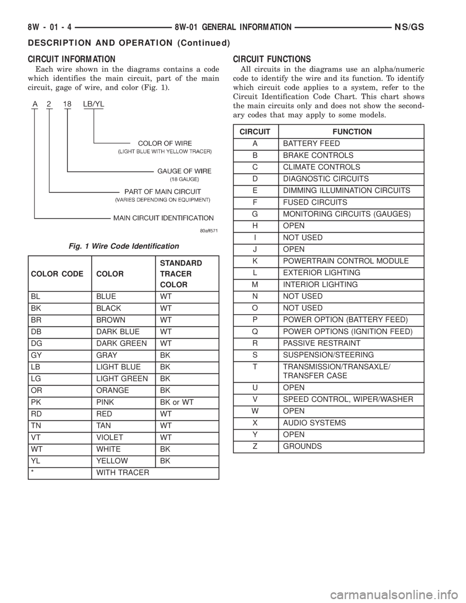
CIRCUIT INFORMATION
Each wire shown in the diagrams contains a code
which identifies the main circuit, part of the main
circuit, gage of wire, and color (Fig. 1).
CIRCUIT FUNCTIONS
All circuits in the diagrams use an alpha/numeric
code to identify the wire and its function. To identify
which circuit code applies to a system, refer to the
Circuit Identification Code Chart. This chart shows
the main circuits only and does not show the second-
ary codes that may apply to some models.
Fig. 1 Wire Code Identification
COLOR CODE COLORSTANDARD
TRACER
COLOR
BL BLUE WT
BK BLACK WT
BR BROWN WT
DB DARK BLUE WT
DG DARK GREEN WT
GY GRAY BK
LB LIGHT BLUE BK
LG LIGHT GREEN BK
OR ORANGE BK
PK PINK BK or WT
RD RED WT
TN TAN WT
VT VIOLET WT
WT WHITE BK
YL YELLOW BK
* WITH TRACER
CIRCUIT FUNCTION
A BATTERY FEED
B BRAKE CONTROLS
C CLIMATE CONTROLS
D DIAGNOSTIC CIRCUITS
E DIMMING ILLUMINATION CIRCUITS
F FUSED CIRCUITS
G MONITORING CIRCUITS (GAUGES)
H OPEN
I NOT USED
J OPEN
K POWERTRAIN CONTROL MODULE
L EXTERIOR LIGHTING
M INTERIOR LIGHTING
N NOT USED
O NOT USED
P POWER OPTION (BATTERY FEED)
Q POWER OPTIONS (IGNITION FEED)
R PASSIVE RESTRAINT
S SUSPENSION/STEERING
T TRANSMISSION/TRANSAXLE/
TRANSFER CASE
U OPEN
V SPEED CONTROL, WIPER/WASHER
W OPEN
X AUDIO SYSTEMS
Y OPEN
Z GROUNDS
8W - 01 - 4 8W-01 GENERAL INFORMATIONNS/GS
DESCRIPTION AND OPERATION (Continued)
Page 570 of 1938
WARNING: BE SURE THAT THE IGNITION SWITCH
ALWAYS IS IN THE OFF POSITION, UNLESS THE
PROCEDURE REQUIRES IT TO BE ON.
WARNING: SET THE PARKING BRAKE WHEN
WORKING ON ANY VEHICLE. AN AUTOMATIC
TRANSMISSION SHOULD BE IN PARK. A MANUAL
TRANSMISSION SHOULD BE IN NEUTRAL.
WARNING: OPERATE THE ENGINE ONLY IN A
WELL-VENTILATED AREA.
WARNING: KEEP AWAY FROM MOVING PARTS
WHEN THE ENGINE IS RUNNING, ESPECIALLY THE
FAN AND BELTS.
WARNING: TO PREVENT SERIOUS BURNS, AVOID
CONTACT WITH HOT PARTS SUCH AS THE RADIA-
TOR, EXHAUST MANIFOLD(S), TAIL PIPE, CATA-
LYTIC CONVERTER, AND MUFFLER.
WARNING: DO NOT ALLOW FLAME OR SPARKS
NEAR THE BATTERY. GASES ARE ALWAYS
PRESENT IN AND AROUND THE BATTERY.
WARNING: ALWAYS REMOVE RINGS, WATCHES,
LOOSE HANGING JEWELRY, AND LOOSE CLOTH-
ING.
TAKE OUTS
The abbreviation T/O is used in the component
location section to indicate a point in which the wir-
ing harness branches out to a component.
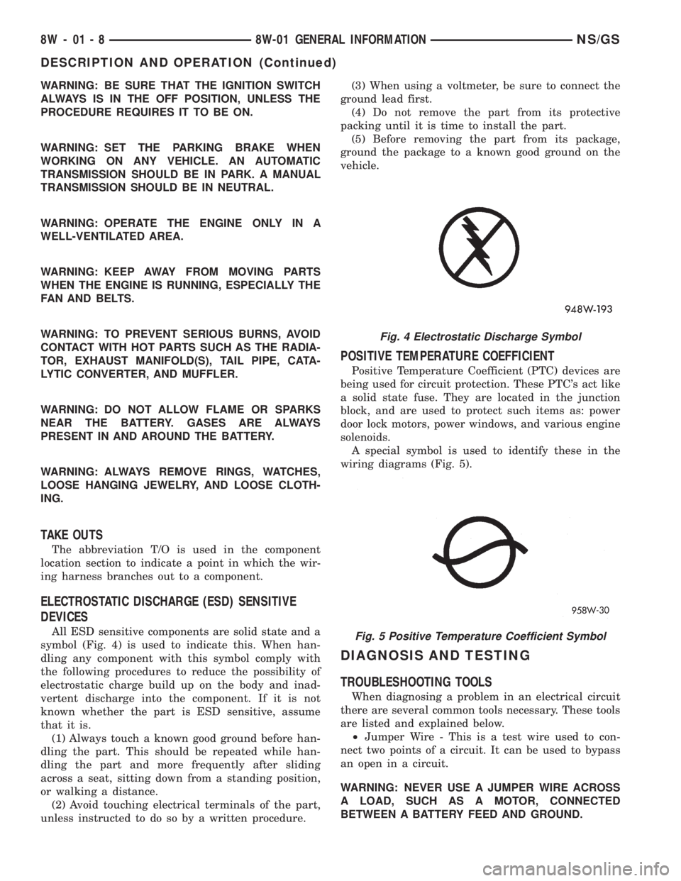
ELECTROSTATIC DISCHARGE (ESD) SENSITIVE
DEVICES
All ESD sensitive components are solid state and a
symbol (Fig. 4) is used to indicate this. When han-
dling any component with this symbol comply with
the following procedures to reduce the possibility of
electrostatic charge build up on the body and inad-
vertent discharge into the component. If it is not
known whether the part is ESD sensitive, assume
that it is.
(1) Always touch a known good ground before han-
dling the part. This should be repeated while han-
dling the part and more frequently after sliding
across a seat, sitting down from a standing position,
or walking a distance.
(2) Avoid touching electrical terminals of the part,
unless instructed to do so by a written procedure.(3) When using a voltmeter, be sure to connect the
ground lead first.
(4) Do not remove the part from its protective
packing until it is time to install the part.
(5) Before removing the part from its package,
ground the package to a known good ground on the
vehicle.
POSITIVE TEMPERATURE COEFFICIENT
Positive Temperature Coefficient (PTC) devices are
being used for circuit protection. These PTC's act like
a solid state fuse. They are located in the junction
block, and are used to protect such items as: power
door lock motors, power windows, and various engine
solenoids.
A special symbol is used to identify these in the
wiring diagrams (Fig. 5).
DIAGNOSIS AND TESTING
TROUBLESHOOTING TOOLS
When diagnosing a problem in an electrical circuit
there are several common tools necessary. These tools
are listed and explained below.
²Jumper Wire - This is a test wire used to con-
nect two points of a circuit. It can be used to bypass
an open in a circuit.
WARNING: NEVER USE A JUMPER WIRE ACROSS
A LOAD, SUCH AS A MOTOR, CONNECTED
BETWEEN A BATTERY FEED AND GROUND.
Fig. 4 Electrostatic Discharge Symbol
Fig. 5 Positive Temperature Coefficient Symbol
8W - 01 - 8 8W-01 GENERAL INFORMATIONNS/GS
DESCRIPTION AND OPERATION (Continued)