glove box CHRYSLER VOYAGER 1996 User Guide
[x] Cancel search | Manufacturer: CHRYSLER, Model Year: 1996, Model line: VOYAGER, Model: CHRYSLER VOYAGER 1996Pages: 1938, PDF Size: 55.84 MB
Page 393 of 1938
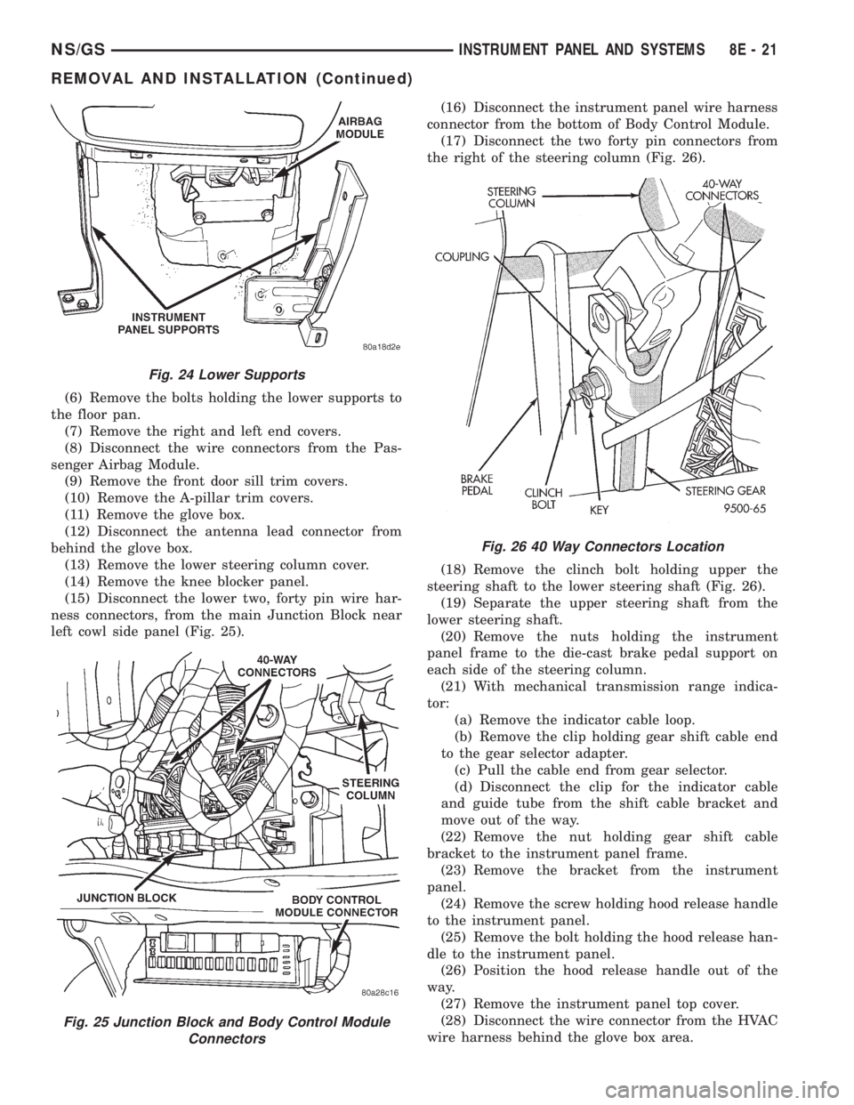
(6) Remove the bolts holding the lower supports to
the floor pan.
(7) Remove the right and left end covers.
(8) Disconnect the wire connectors from the Pas-
senger Airbag Module.
(9) Remove the front door sill trim covers.
(10) Remove the A-pillar trim covers.
(11) Remove the glove box.
(12) Disconnect the antenna lead connector from
behind the glove box.
(13) Remove the lower steering column cover.
(14) Remove the knee blocker panel.
(15) Disconnect the lower two, forty pin wire har-
ness connectors, from the main Junction Block near
left cowl side panel (Fig. 25).(16) Disconnect the instrument panel wire harness
connector from the bottom of Body Control Module.
(17) Disconnect the two forty pin connectors from
the right of the steering column (Fig. 26).
(18) Remove the clinch bolt holding upper the
steering shaft to the lower steering shaft (Fig. 26).
(19) Separate the upper steering shaft from the
lower steering shaft.
(20) Remove the nuts holding the instrument
panel frame to the die-cast brake pedal support on
each side of the steering column.
(21) With mechanical transmission range indica-
tor:
(a) Remove the indicator cable loop.
(b) Remove the clip holding gear shift cable end
to the gear selector adapter.
(c) Pull the cable end from gear selector.
(d) Disconnect the clip for the indicator cable
and guide tube from the shift cable bracket and
move out of the way.
(22) Remove the nut holding gear shift cable
bracket to the instrument panel frame.
(23) Remove the bracket from the instrument
panel.
(24) Remove the screw holding hood release handle
to the instrument panel.
(25) Remove the bolt holding the hood release han-
dle to the instrument panel.
(26) Position the hood release handle out of the
way.
(27) Remove the instrument panel top cover.
(28) Disconnect the wire connector from the HVAC
wire harness behind the glove box area.
Fig. 24 Lower Supports
Fig. 25 Junction Block and Body Control Module
Connectors
Fig. 26 40 Way Connectors Location
NS/GSINSTRUMENT PANEL AND SYSTEMS 8E - 21
REMOVAL AND INSTALLATION (Continued)
Page 398 of 1938
(3) Remove reinforcement.
INSTALLATION
(1) Place reinforcement in position.
(2) Install screws to hold knee blocker reinforce-
ment to instrument panel.
(3) Install lower steering column cover.
LOWER CONSOLE
REMOVAL
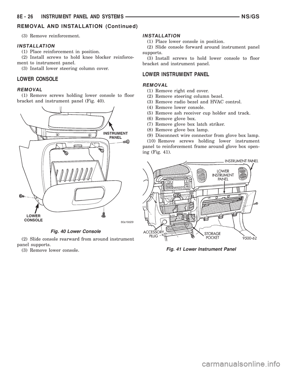
(1) Remove screws holding lower console to floor
bracket and instrument panel (Fig. 40).
(2) Slide console rearward from around instrument
panel supports.
(3) Remove lower console.
INSTALLATION
(1) Place lower console in position.
(2) Slide console forward around instrument panel
supports.
(3) Install screws to hold lower console to floor
bracket and instrument panel.
LOWER INSTRUMENT PANEL
REMOVAL
(1) Remove right end cover.
(2) Remove steering column bezel.
(3) Remove radio bezel and HVAC control.
(4) Remove lower console.
(5) Remove ash receiver cup holder and track.
(6) Remove glove box.
(7) Remove glove box latch striker.
(8) Remove glove box lamp.
(9) Disconnect wire connector from glove box lamp.
(10) Remove screws holding lower instrument
panel to reinforcement frame around glove box open-
ing (Fig. 41).
Fig. 40 Lower Console
Fig. 41 Lower Instrument Panel
8E - 26 INSTRUMENT PANEL AND SYSTEMSNS/GS
REMOVAL AND INSTALLATION (Continued)
Page 404 of 1938

CD/3-band graphic equalizer (RBR sales code), or an
AM/FM/CD/cassette/3-band graphic equalizer (RAZ
sales code).
All factory-installed radio receivers are stereo Elec-
tronically Tuned Radios (ETR) and include an elec-
tronic digital clock function.
All factory-installed radio receivers, except the
RAS model, communicate on the Chrysler Collision
Detection (CCD) data bus network through a sepa-
rate two-way wire harness connector. The CCD data
bus network allows the sharing of sensor informa-
tion. This helps to reduce wire harness complexity,
internal controller hardware, and component sensor
current loads. At the same time, this system provides
increased reliability, enhanced diagnostics, and
allows the addition of many new feature capabilities.
In addition, radios connected to the CCD data bus
have several audio system functions that can be diag-
nosed using a DRB scan tool. Refer to the proper
Diagnostic Procedures manual for more information
on DRB testing of the audio systems.
The radio can only be serviced by an authorized
radio repair station. Refer to the latest Warranty Pol-
icies and Procedures manual for a current listing of
authorized radio repair stations.
For more information on radio features, setting
procedures, and control functions refer to the owner's
manual in the vehicle glove box.
RADIO IGNITION INTERFERENCE
If receiving ignition/engine interference noise on
the radio stations, check and clean all engine and
body ground connections. Tighten properly after
cleaning. Example (Fig. 1), (Fig. 2), (Fig. 3) and (Fig.
4).
Ensure all ground connections are without corro-
sion.
CHOKEÐINFINITY SPEAKERS
If the audio system is lacking bass response, check
for continuity across the choke connector. If no conti-
nuity Replace choke. The choke is located on the
Fig. 1 Motor Mount to Frame Rail Ground
Fig. 2 2.4L Engine Block Ground
Fig. 3 3.0L Engine Block Ground
Fig. 4 3.3/3.8L Engine Block Ground
8F - 2 AUDIO SYSTEMSNS
DESCRIPTION AND OPERATION (Continued)
Page 405 of 1938

bracket behind the junction block/body control mod-
ule (Fig. 5).
REMOTE RADIO SWITCHES
A remote radio control switch option is available on
LXI models sold in North America with the AM/FM/
cassette/5-band graphic equalizer with CD changer
control feature (RBN sales code), or the AM/FM/CD/
cassette/3-band graphic equalizer (RAZ sales code)
radio receivers. Two rocker-type switches are
mounted on the back (instrument panel side) of the
steering wheel spokes. The switch on the left spoke is
the seek switch and has seek up, seek down, and pre-
set station advance functions. The switch on the
right spoke is the volume control switch and has vol-
ume up, and volume down functions (Fig. 6).
These switches are resistor multiplexed units that
are hard-wired to the Body Control Module (BCM)
through the clockspring. The BCM sends the propermessages on the Chrysler Collision Detection (CCD)
data bus network to the radio receiver. For diagnosis
of the BCM or the CCD data bus, the use of a DRB
scan tool and the proper Diagnostic Procedures man-
ual are recommended. For more information on the
operation of the remote radio switch controls, refer to
the owner's manual in the vehicle glove box.
NAME BRAND SPEAKER RELAY
Relay is located in the junction block. To test relay
refer to the Audio Diagnostic Test Procedures or use
a known good relay.
DIAGNOSIS AND TESTING
ANTENNA
WARNING: ON VEHICLES EQUIPPED WITH AIR-
BAGS, REFER TO GROUP 8M - PASSIVE
RESTRAINT SYSTEMS BEFORE ATTEMPTING ANY
STEERING WHEEL, STEERING COLUMN, OR
INSTRUMENT PANEL COMPONENT DIAGNOSIS OR
SERVICE. FAILURE TO TAKE THE PROPER PRE-
CAUTIONS COULD RESULT IN ACCIDENTAL AIR-
BAG DEPLOYMENT AND POSSIBLE PERSONAL
INJURY.
The following four tests are used to diagnose the
antenna with an ohmmeter:
²Test 1- Mast to ground test
²Test 2- Tip-of-mast to tip-of-conductor test
²Test 3- Body ground to battery ground test
²Test 4- Body ground to coaxial shield test.
The ohmmeter test lead connections for each test
are shown in Antenna Tests (Fig. 7).
NOTE: This model has a two-piece antenna coaxial
cable. Tests 2 and 4 must be conducted in two
steps to isolate a coaxial cable problem; from the
coaxial cable connection under the right end of the
instrument panel near the right cowl side panel to
the antenna base, and then from the coaxial cable
connection to the radio chassis connection.
TEST 1
Test 1 determines if the antenna mast is insulated
from the base. Proceed as follows:
(1) Unplug the antenna coaxial cable connector
from the radio chassis and isolate.
(2) Connect one ohmmeter test lead to the tip of
the antenna mast. Connect the other test lead to the
antenna base. Check for continuity.
(3) There should be no continuity. If continuity is
found, replace the faulty or damaged antenna base
and cable assembly.
Fig. 5 Choke Location
Fig. 6 Remote Radio Switch Operational View
NSAUDIO SYSTEMS 8F - 3
DESCRIPTION AND OPERATION (Continued)
Page 409 of 1938
REMOVAL AND INSTALLATION
ANTENNA MAST AND CABLE LEAD
REMOVAL
(1) Remove glove box from instrument panel, refer
to Group 8E, Instrument Panel and Systems for
proper procedures.
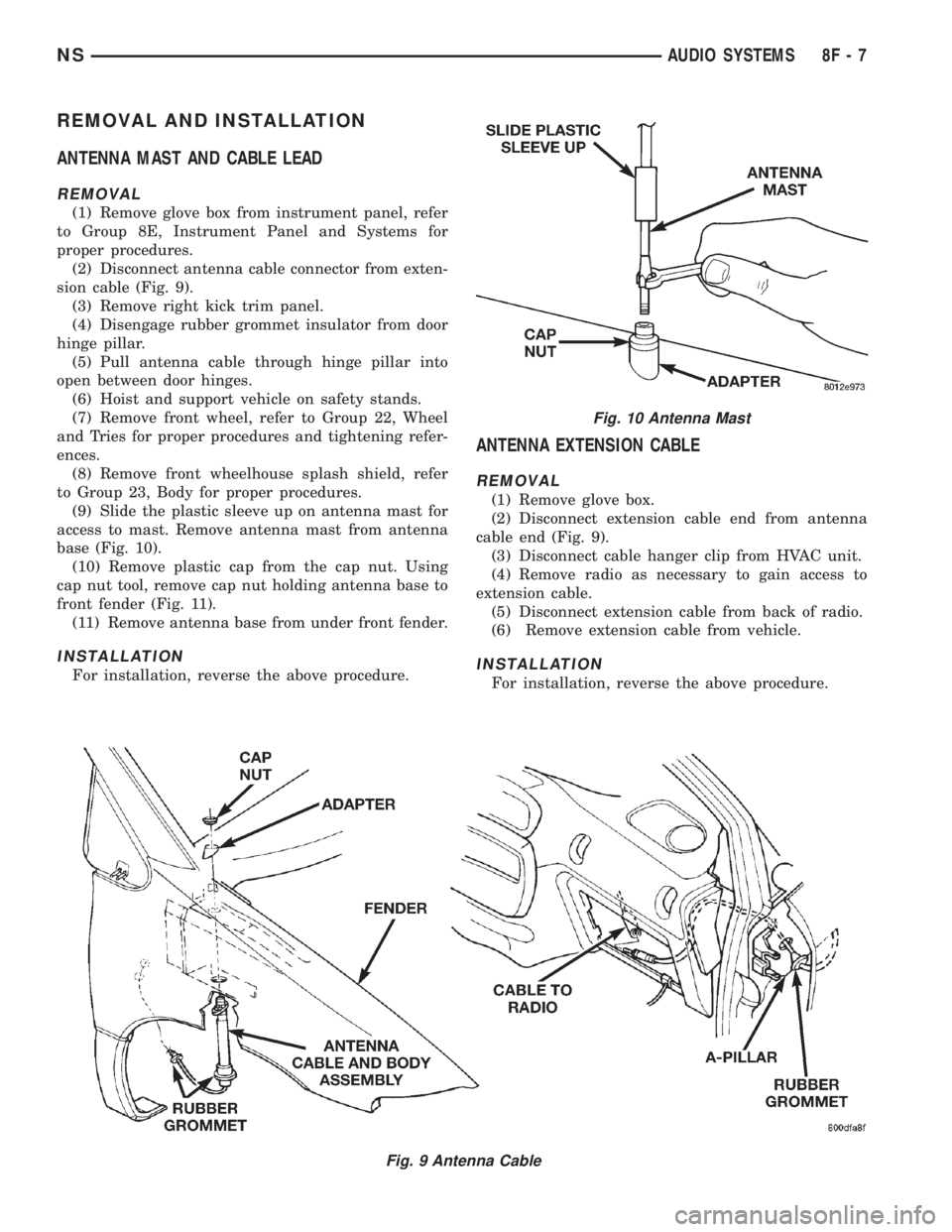
(2) Disconnect antenna cable connector from exten-
sion cable (Fig. 9).
(3) Remove right kick trim panel.
(4) Disengage rubber grommet insulator from door
hinge pillar.
(5) Pull antenna cable through hinge pillar into
open between door hinges.
(6) Hoist and support vehicle on safety stands.
(7) Remove front wheel, refer to Group 22, Wheel
and Tries for proper procedures and tightening refer-
ences.
(8) Remove front wheelhouse splash shield, refer
to Group 23, Body for proper procedures.
(9) Slide the plastic sleeve up on antenna mast for
access to mast. Remove antenna mast from antenna
base (Fig. 10).
(10) Remove plastic cap from the cap nut. Using
cap nut tool, remove cap nut holding antenna base to
front fender (Fig. 11).
(11) Remove antenna base from under front fender.
INSTALLATION
For installation, reverse the above procedure.
ANTENNA EXTENSION CABLE
REMOVAL
(1) Remove glove box.
(2) Disconnect extension cable end from antenna
cable end (Fig. 9).
(3) Disconnect cable hanger clip from HVAC unit.
(4) Remove radio as necessary to gain access to
extension cable.
(5) Disconnect extension cable from back of radio.
(6) Remove extension cable from vehicle.
INSTALLATION
For installation, reverse the above procedure.
Fig. 9 Antenna Cable
Fig. 10 Antenna Mast
NSAUDIO SYSTEMS 8F - 7
Page 470 of 1938
INTERIOR LAMPS
INDEX
page page
REMOVAL AND INSTALLATION
CONVENIENCE BIN LAMP................. 20
DOME LAMP BULB...................... 21
DOME LAMP........................... 21
FRONT DOOR COURTESY LAMP BULB...... 22
FRONT DOOR COURTESY LAMP........... 21
GLOVE BOX LAMP AND SWITCH........... 19
GLOVE BOX LAMP BULB.................. 19
HEADER READING/COURTESY LAMP BULB . . . 19HEADER READING/COURTESY LAMP....... 18
IGNITION HALO LAMP BULB............... 19
INSTRUMENT PANEL LAMPS AND SWITCHES . 20
LIFTGATE COURTESY LAMP BULB.......... 24
LIFTGATE COURTESY LAMP............... 23
OVERHEAD CONSOLE READING/COURTESY
LAMP BULB.......................... 18
RAIL LAMP MODULE BULB................ 23
REMOVAL AND INSTALLATION
OVERHEAD CONSOLE READING/COURTESY LAMP
BULB
REMOVAL
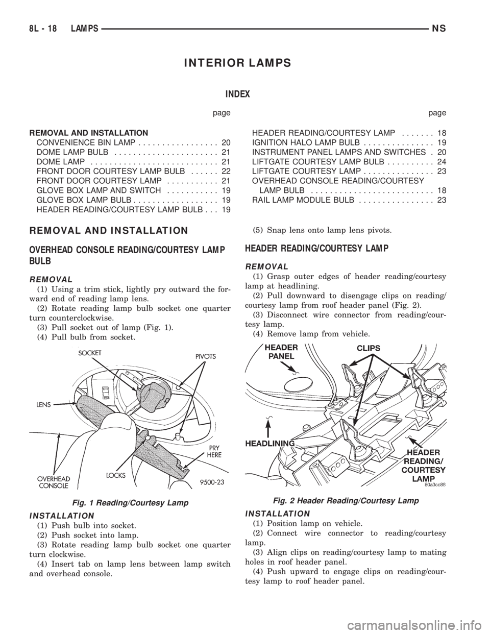
(1) Using a trim stick, lightly pry outward the for-
ward end of reading lamp lens.
(2) Rotate reading lamp bulb socket one quarter
turn counterclockwise.
(3) Pull socket out of lamp (Fig. 1).
(4) Pull bulb from socket.
INSTALLATION
(1) Push bulb into socket.
(2) Push socket into lamp.
(3) Rotate reading lamp bulb socket one quarter
turn clockwise.
(4) Insert tab on lamp lens between lamp switch
and overhead console.(5) Snap lens onto lamp lens pivots.
HEADER READING/COURTESY LAMP
REMOVAL
(1) Grasp outer edges of header reading/courtesy
lamp at headlining.
(2) Pull downward to disengage clips on reading/
courtesy lamp from roof header panel (Fig. 2).
(3) Disconnect wire connector from reading/cour-
tesy lamp.
(4) Remove lamp from vehicle.
INSTALLATION
(1) Position lamp on vehicle.
(2) Connect wire connector to reading/courtesy
lamp.
(3) Align clips on reading/courtesy lamp to mating
holes in roof header panel.
(4) Push upward to engage clips on reading/cour-
tesy lamp to roof header panel.
Fig. 1 Reading/Courtesy LampFig. 2 Header Reading/Courtesy Lamp
8L - 18 LAMPSNS
Page 471 of 1938
HEADER READING/COURTESY LAMP BULB
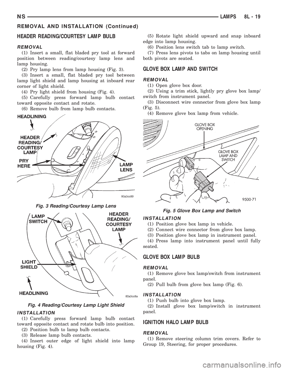
REMOVAL
(1) Insert a small, flat bladed pry tool at forward
position between reading/courtesy lamp lens and
lamp housing.
(2) Pry lamp lens from lamp housing (Fig. 3).
(3) Insert a small, flat bladed pry tool between
lamp light shield and lamp housing at inboard rear
corner of light shield.
(4) Pry light shield from housing (Fig. 4).
(5) Carefully press forward lamp bulb contact
toward opposite contact and rotate.
(6) Remove bulb from lamp bulb contacts.
INSTALLATION
(1) Carefully press forward lamp bulb contact
toward opposite contact and rotate bulb into position.
(2) Position bulb to lamp bulb contacts.
(3) Release lamp bulb contacts.
(4) Insert outer edge of light shield into lamp
housing (Fig. 4).(5) Rotate light shield upward and snap inboard
edge into lamp housing.
(6) Position lens switch tab to lamp switch.
(7) Press lens pivots to tabs on lamp housing until
both pivots are seated.
GLOVE BOX LAMP AND SWITCH
REMOVAL
(1) Open glove box door.
(2) Using a trim stick, lightly pry glove box lamp/
switch from instrument panel.
(3) Disconnect wire connector from glove box lamp
(Fig. 5).
(4) Remove glove box lamp from vehicle.
INSTALLATION
(1) Position glove box lamp in vehicle.
(2) Connect wire connector from glove box lamp.
(3) Position glove box lamp in instrument panel.
(4) Press lamp into instrument panel until fully
seated.
GLOVE BOX LAMP BULB
REMOVAL
(1) Remove glove box lamp/switch from instrument
panel.
(2) Pull bulb from glove box lamp (Fig. 6).
INSTALLATION
(1) Push bulb into glove box lamp.
(2) Install glove box lamp/switch in instrument
panel.
IGNITION HALO LAMP BULB
REMOVAL
(1) Remove steering column trim covers. Refer to
Group 19, Steering, for proper procedures.
Fig. 3 Reading/Courtesy Lamp Lens
Fig. 4 Reading/Courtesy Lamp Light Shield
Fig. 5 Glove Box Lamp and Switch
NSLAMPS 8L - 19
REMOVAL AND INSTALLATION (Continued)
Page 472 of 1938
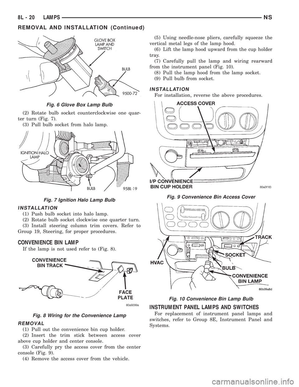
(2) Rotate bulb socket counterclockwise one quar-
ter turn (Fig. 7).
(3) Pull bulb socket from halo lamp.
INSTALLATION
(1) Push bulb socket into halo lamp.
(2) Rotate bulb socket clockwise one quarter turn.
(3) Install steering column trim covers. Refer to
Group 19, Steering, for proper procedures.
CONVENIENCE BIN LAMP
If the lamp is not used refer to (Fig. 8).
REMOVAL
(1) Pull out the convenience bin cup holder.
(2) Insert the trim stick between access cover
above cup holder and center console.
(3) Carefully pry the access cover from the center
console (Fig. 9).
(4) Remove the access cover from the vehicle.(5) Using needle-nose pliers, carefully squeeze the
vertical metal legs of the lamp hood.
(6) Lift the lamp hood upward from the cup holder
tray.
(7) Carefully pull the lamp and wiring rearward
from the instrument panel (Fig. 10).
(8) Pull the lamp hood from the lamp socket.
(9) Pull bulb from socket.
INSTALLATION
For installation, reverse the above procedures.
INSTRUMENT PANEL LAMPS AND SWITCHES
For replacement of instrument panel lamps and
switches, refer to Group 8E, Instrument Panel and
Systems.
Fig. 6 Glove Box Lamp Bulb
Fig. 7 Ignition Halo Lamp Bulb
Fig. 8 Wiring for the Convenience Lamp
Fig. 9 Convenience Bin Access Cover
Fig. 10 Convenience Bin Lamp Bulb
8L - 20 LAMPSNS
REMOVAL AND INSTALLATION (Continued)
Page 477 of 1938
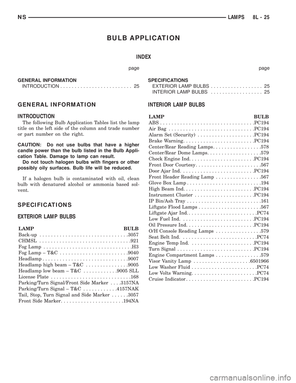
BULB APPLICATION
INDEX
page page
GENERAL INFORMATION
INTRODUCTION......................... 25SPECIFICATIONS
EXTERIOR LAMP BULBS.................. 25
INTERIOR LAMP BULBS.................. 25
GENERAL INFORMATION
INTRODUCTION
The following Bulb Application Tables list the lamp
title on the left side of the column and trade number
or part number on the right.
CAUTION: Do not use bulbs that have a higher
candle power than the bulb listed in the Bulb Appli-
cation Table. Damage to lamp can result.
Do not touch halogen bulbs with fingers or other
possibly oily surfaces. Bulb life will be reduced.
If a halogen bulb is contaminated with oil, clean
bulb with denatured alcohol or ammonia based sol-
vent.
SPECIFICATIONS
EXTERIOR LAMP BULBS
LAMP BULB
Back-up...............................3057
CHMSL................................921
Fog Lamp...............................H3
FogLamp±T&C ........................9040
Headlamp..............................9007
Headlamp high beam ± T&C...............9005
Headlamp low beam ± T&C............9005 SLL
License Plate............................168
Parking/Turn Signal/Front Side Marker. . . .3157NA
Parking/Turn Signal ± T&C............4157NAK
Tail, Stop, Turn Signal and Side Marker......3057
Front Side Marker......................194NA
INTERIOR LAMP BULBS
LAMP BULB
ABS.................................PC194
AirBag ..............................PC194
Alarm Set (Security)....................PC194
Brake Warning.........................PC194
Center/Rear Reading Lamps.................578
Center/Rear Dome Lamps...................579
Check Engine Ind.......................PC194
Front Door Courtesy.......................567
Door Ajar Ind..........................PC194
Front Header Reading Lamp................567
Glove Box Lamp..........................194
High Beam Ind.........................PC194
Instrument Cluster.....................PC194
IP Bin/Ash Tray..........................161
Liftgate Flood Lamps......................567
Liftgate Ajar Ind.........................PC74
Low Fuel Ind..........................PC194
Oil Pressure Ind........................PC194
O/H Console Reading Lamps................579
Seat Belt Ind...........................PC74
Engine Temp Ind.......................PC194
Turn Signal...........................PC194
Engine Compartment Lamps................579
Visor Vanity Lamp....................6501966
Low Washer Fluid.......................PC74
Low Volts Warning.......................PC74
Cruise Indicator........................PC194
NSLAMPS 8L - 25
Page 495 of 1938
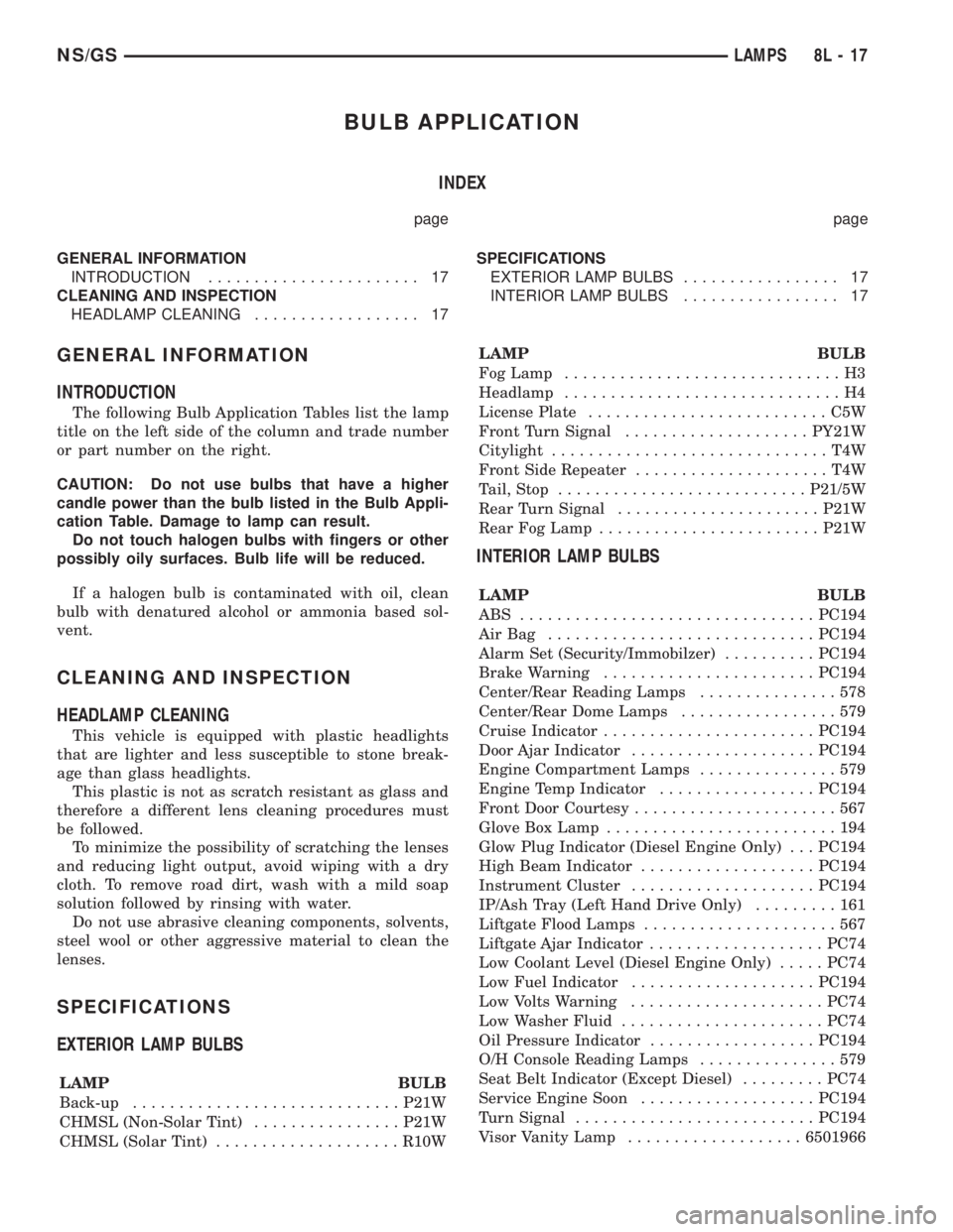
BULB APPLICATION
INDEX
page page
GENERAL INFORMATION
INTRODUCTION....................... 17
CLEANING AND INSPECTION
HEADLAMP CLEANING.................. 17SPECIFICATIONS
EXTERIOR LAMP BULBS................. 17
INTERIOR LAMP BULBS................. 17
GENERAL INFORMATION
INTRODUCTION
The following Bulb Application Tables list the lamp
title on the left side of the column and trade number
or part number on the right.
CAUTION: Do not use bulbs that have a higher
candle power than the bulb listed in the Bulb Appli-
cation Table. Damage to lamp can result.
Do not touch halogen bulbs with fingers or other
possibly oily surfaces. Bulb life will be reduced.
If a halogen bulb is contaminated with oil, clean
bulb with denatured alcohol or ammonia based sol-
vent.
CLEANING AND INSPECTION
HEADLAMP CLEANING
This vehicle is equipped with plastic headlights
that are lighter and less susceptible to stone break-
age than glass headlights.
This plastic is not as scratch resistant as glass and
therefore a different lens cleaning procedures must
be followed.
To minimize the possibility of scratching the lenses
and reducing light output, avoid wiping with a dry
cloth. To remove road dirt, wash with a mild soap
solution followed by rinsing with water.
Do not use abrasive cleaning components, solvents,
steel wool or other aggressive material to clean the
lenses.
SPECIFICATIONS
EXTERIOR LAMP BULBS
LAMP BULB
Back-up.............................P21W
CHMSL (Non-Solar Tint)................P21W
CHMSL (Solar Tint)....................R10WLAMP BULB
Fog Lamp..............................H3
Headlamp..............................H4
License Plate..........................C5W
Front Turn Signal....................PY21W
Citylight..............................T4W
Front Side Repeater.....................T4W
Tail, Stop...........................P21/5W
Rear Turn Signal......................P21W
Rear Fog Lamp........................P21W
INTERIOR LAMP BULBS
LAMP BULB
ABS ................................PC194
AirBag .............................PC194
Alarm Set (Security/Immobilzer)..........PC194
Brake Warning.......................PC194
Center/Rear Reading Lamps...............578
Center/Rear Dome Lamps.................579
Cruise Indicator.......................PC194
Door Ajar Indicator....................PC194
Engine Compartment Lamps...............579
Engine Temp Indicator.................PC194
Front Door Courtesy......................567
Glove Box Lamp.........................194
Glow Plug Indicator (Diesel Engine Only) . . . PC194
High Beam Indicator...................PC194
Instrument Cluster....................PC194
IP/Ash Tray (Left Hand Drive Only).........161
Liftgate Flood Lamps.....................567
Liftgate Ajar Indicator...................PC74
Low Coolant Level (Diesel Engine Only).....PC74
Low Fuel Indicator....................PC194
Low Volts Warning.....................PC74
Low Washer Fluid......................PC74
Oil Pressure Indicator..................PC194
O/H Console Reading Lamps...............579
Seat Belt Indicator (Except Diesel).........PC74
Service Engine Soon...................PC194
Turn Signal..........................PC194
Visor Vanity Lamp...................6501966
NS/GSLAMPS 8L - 17