key battery CHRYSLER VOYAGER 1996 User Guide
[x] Cancel search | Manufacturer: CHRYSLER, Model Year: 1996, Model line: VOYAGER, Model: CHRYSLER VOYAGER 1996Pages: 1938, PDF Size: 55.84 MB
Page 299 of 1938

IGNITION SYSTEM
CONTENTS
page page
GENERAL INFORMATION................... 1
2.4L ENGINE............................ 16
3.0L ENGINE............................ 233.3/3.8L ENGINE........................ 28
IGNITION SWITCH AND LOCK CYLINDER..... 35
GENERAL INFORMATION
INDEX
page page
GENERAL INFORMATION
AUTOMATIC SHUTDOWN (ASD) RELAY....... 4
CAMSHAFT POSITION SENSOR............. 5
CRANKSHAFT POSITION SENSOR........... 5
ENGINE COOLANT TEMPERATURE (ECT)
SENSOR.............................. 6
IGNITION COIL.......................... 4
IGNITION SYSTEM....................... 2
INTRODUCTION......................... 1
KNOCK SENSOR......................... 7
LOCK KEY CYLINDER..................... 7
MANIFOLD ABSOLUTE PRESSURE (MAP)
SENSOR.............................. 6
POWERTRAIN CONTROL MODULE........... 1
SPARK PLUG CABLE...................... 3
SPARK PLUGSÐ2.4/3.0L................... 2
SPARK PLUGSÐ3.3/3.8L................... 2
THROTTLE POSITION SENSOR (TPS)........ 7DIAGNOSIS AND TESTING
CAMSHAFT POSITION SENSOR AND
CRANKSHAFT POSITION SENSOR......... 11
CHECK COIL TESTÐ2.4L.................. 9
CHECK COIL TESTÐ3.3/3.8L................ 9
ENGINE COOLANT TEMPERATURE SENSOR . . 11
FAILURE TO START TEST................. 10
IGNITION TIMING PROCEDURE............ 11
INTAKE AIR TEMPERATURE SENSOR........ 11
MANIFOLD ABSOLUTE PRESSURE (MAP)
SENSOR TEST........................ 11
SPARK PLUG CONDITION................. 11
TESTING FOR SPARK AT COILÐ2.4/3.3/3.8L
ENGINES............................. 8
TESTING FOR SPARK AT COILÐ3.0L......... 8
THROTTLE POSITION SENSOR............ 13
SERVICE PROCEDURES
IGNITION TIMING PROCEDURE............ 15
POWERTRAIN CONTROL MODULE.......... 13
SPARK PLUG GAP ADJUSTMENT........... 13
GENERAL INFORMATION
INTRODUCTION
This group describes the ignition systems for the
2.4, 3.0, and 3.3/3.8L engines.
On Board Diagnostics is described in Group 25 -
Emission Control Systems.
Group 0 - Lubrication and Maintenance, contains
general maintenance information for ignition related
items. The Owner's Manual also contains mainte-
nance information.
POWERTRAIN CONTROL MODULE
The ignition system is regulated by the Powertrain
Control Module (PCM) (Fig. 1). The PCM supplies
battery voltage to the ignition coil through the Auto
Shutdown (ASD) Relay. The PCM also controls
ground circuit for the ignition coil. By switching the
ground path for the coil on and off, the PCM adjusts
ignition timing to meet changing engine operating
conditions.
During the crank-start period the PCM advances
ignition timing a set amount. During engine opera-
tion, the amount of spark advance provided by the
PCM is determined by the following input factors:
NSIGNITION SYSTEM 8D - 1
Page 308 of 1938

(3) Remove ignition cables from the secondary tow-
ers of the coil. Measure the secondary resistance of
the coil between the towers of each individual coil
(Fig. 21). Secondary resistance should be 7,000 to
15,800 ohms. Replace the coil if resistance is not
within tolerance.
FAILURE TO START TEST
This no-start test checks the camshaft position sen-
sor and crankshaft position sensor.
The Powertrain Control Module (PCM) supplies 8
volts to the camshaft position sensor and crankshaft
position sensor through one circuit. If the 8 volt sup-
ply circuit shorts to ground, neither sensor will pro-
duce a signal (output voltage to the PCM).
When the ignition key is turned and left in the On
position, the PCM automatically energizes the Auto
Shutdown (ASD) relay. However, the controller de-en-
ergizes the relay within one second because it has
not received a camshaft position sensor signal indi-
cating engine rotation.
During cranking, the ASD relay will not energize
until the PCM receives a camshaft position sensor
signal. Secondly, the ASD relay remains energized
only if the controller senses a crankshaft position
sensor signal immediately after detecting the cam-
shaft position sensor signal.
(1) Check battery voltage. Voltage should be
approximately 12.66 volts or higher to perform fail-
ure to start test.
(2) Disconnect the harness connector from the coil
pack.
(3) Connect a test light to the B+ (battery voltage)
terminal of the coil electrical connector and ground
as shown in (Fig. 22). The B+ wire for the DIS coil is
dark green with an orange tracer.Do not spread
the terminal with the test light probe.(4) Turn the ignition key to theON position.The
test light should flash On and then Off.Do not turn
the Key to off position, leave it in the On posi-
tion.
(a) If the test light flashes momentarily, the
PCM grounded the Auto Shutdown (ASD) relay.
Proceed to step 5.
(b) If the test light did not flash, the ASD relay
did not energize. The cause is either the relay or
one of the relay circuits. Use the DRB scan tool to
test the ASD relay and circuits. Refer to the appro-
priate Powertrain Diagnostics Procedure Manual.
Refer to the wiring diagrams section for circuit
information.
(5) Crank the engine. (If the key was placed in the
off position after step 4, place the key in the On posi-
tion before cranking. Wait for the test light to flash
once, then crank the engine.)
(6) If the test light momentarily flashes during
cranking, the PCM is not receiving a crankshaft posi-
tion sensor signal. Use the DRB scan tool to test the
crankshaft position sensor and sensor circuits. Refer
to the appropriate Powertrain Diagnostics Procedure
Manual. Refer to the wiring diagrams section for cir-
cuit information.
(7) If the test light did not flash during cranking,
unplug the crankshaft position sensor connector.
Turn the ignition key to the off position. Turn the
key to the On position, wait for the test light to
momentarily flash once, then crank the engine. If the
test light momentarily flashes, the crankshaft posi-
tion sensor is shorted and must be replaced. If the
light did not flash, the cause of the no-start is in
Fig. 21 Checking Ignition Coil Secondary
ResistanceFig. 22 Ignition Coil Engine Harness Connector
8D - 10 IGNITION SYSTEMNS
DIAGNOSIS AND TESTING (Continued)
Page 334 of 1938
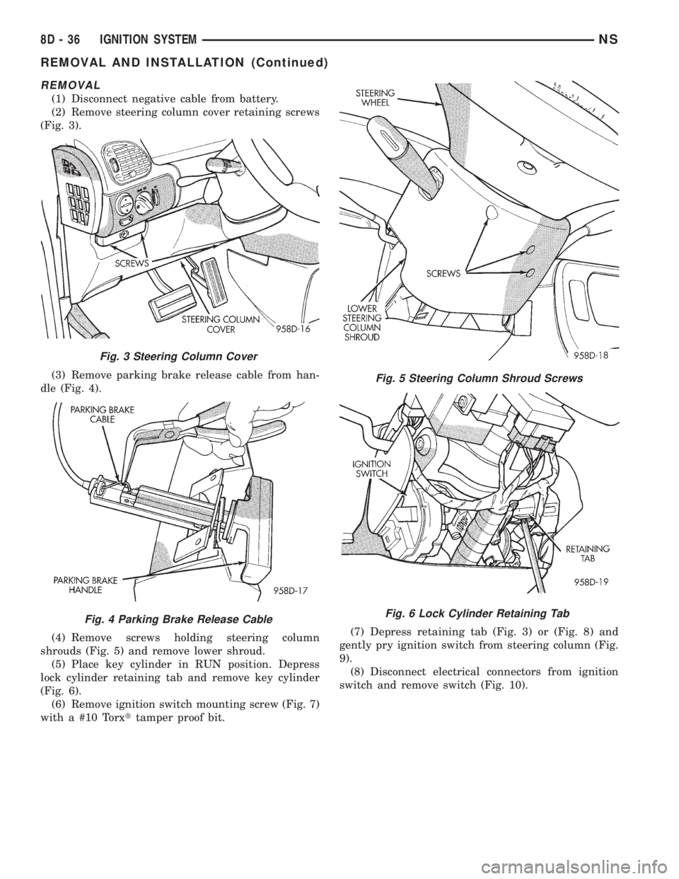
REMOVAL
(1) Disconnect negative cable from battery.
(2) Remove steering column cover retaining screws
(Fig. 3).
(3) Remove parking brake release cable from han-
dle (Fig. 4).
(4) Remove screws holding steering column
shrouds (Fig. 5) and remove lower shroud.
(5) Place key cylinder in RUN position. Depress
lock cylinder retaining tab and remove key cylinder
(Fig. 6).
(6) Remove ignition switch mounting screw (Fig. 7)
with a #10 Torxttamper proof bit.(7) Depress retaining tab (Fig. 3) or (Fig. 8) and
gently pry ignition switch from steering column (Fig.
9).
(8) Disconnect electrical connectors from ignition
switch and remove switch (Fig. 10).
Fig. 3 Steering Column Cover
Fig. 4 Parking Brake Release Cable
Fig. 5 Steering Column Shroud Screws
Fig. 6 Lock Cylinder Retaining Tab
8D - 36 IGNITION SYSTEMNS
REMOVAL AND INSTALLATION (Continued)
Page 335 of 1938
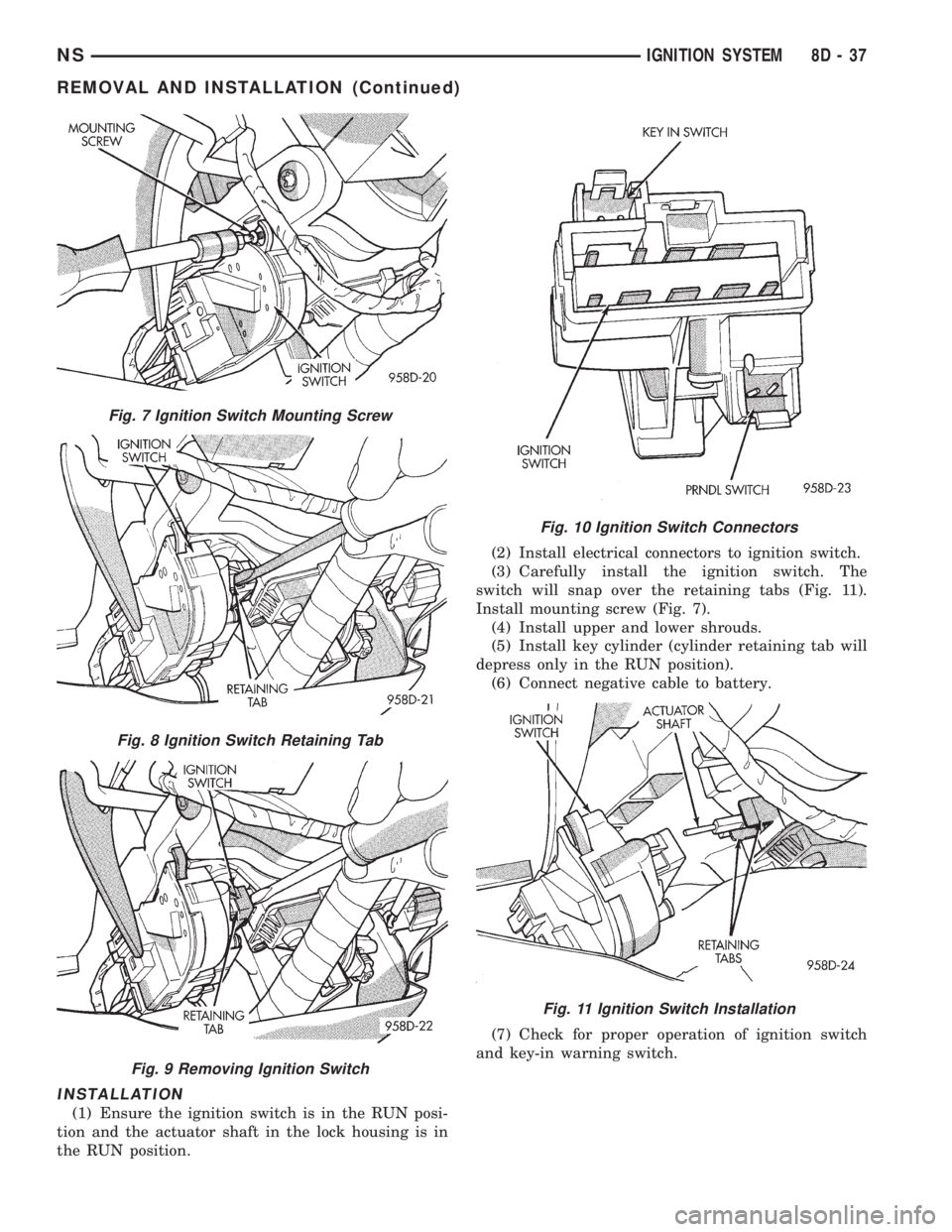
INSTALLATION
(1) Ensure the ignition switch is in the RUN posi-
tion and the actuator shaft in the lock housing is in
the RUN position.(2) Install electrical connectors to ignition switch.
(3) Carefully install the ignition switch. The
switch will snap over the retaining tabs (Fig. 11).
Install mounting screw (Fig. 7).
(4) Install upper and lower shrouds.
(5) Install key cylinder (cylinder retaining tab will
depress only in the RUN position).
(6) Connect negative cable to battery.
(7) Check for proper operation of ignition switch
and key-in warning switch.
Fig. 7 Ignition Switch Mounting Screw
Fig. 8 Ignition Switch Retaining Tab
Fig. 9 Removing Ignition Switch
Fig. 10 Ignition Switch Connectors
Fig. 11 Ignition Switch Installation
NSIGNITION SYSTEM 8D - 37
REMOVAL AND INSTALLATION (Continued)
Page 336 of 1938
LOCK KEY CYLINDER
REMOVAL
(1) Disconnect negative cable from battery.
(2) Remove steering column cover retaining screws
(Fig. 3).
(3) Remove screws holding steering column
shrouds (Fig. 5) and remove lower shroud.
(4) Place key cylinder in RUN position. Depress
lock cylinder retaining tab and remove key cylinder
(Fig. 6).
INSTALLATION
(1) Install key in lock cylinder. Turn key to run
position (retaining tab on lock cylinder can be
depressed).
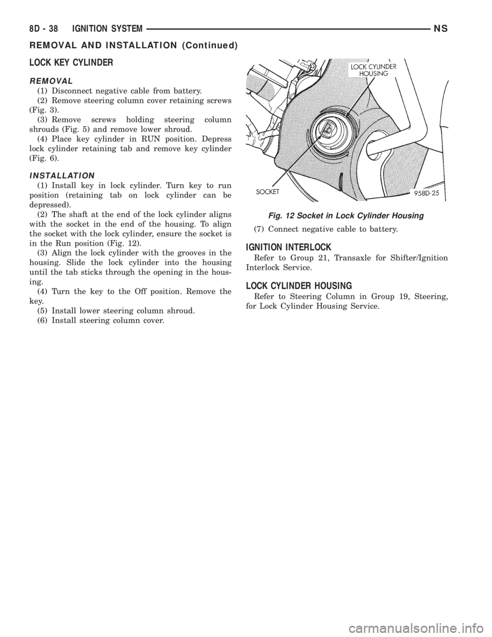
(2) The shaft at the end of the lock cylinder aligns
with the socket in the end of the housing. To align
the socket with the lock cylinder, ensure the socket is
in the Run position (Fig. 12).
(3) Align the lock cylinder with the grooves in the
housing. Slide the lock cylinder into the housing
until the tab sticks through the opening in the hous-
ing.
(4) Turn the key to the Off position. Remove the
key.
(5) Install lower steering column shroud.
(6) Install steering column cover.(7) Connect negative cable to battery.
IGNITION INTERLOCK
Refer to Group 21, Transaxle for Shifter/Ignition
Interlock Service.
LOCK CYLINDER HOUSING
Refer to Steering Column in Group 19, Steering,
for Lock Cylinder Housing Service.
Fig. 12 Socket in Lock Cylinder Housing
8D - 38 IGNITION SYSTEMNS
REMOVAL AND INSTALLATION (Continued)
Page 425 of 1938
INSTALLATION
Transfer speed control cable to replacement speed
control servo. Reverse the preceding operation.
SPEED CONTROL SWITCHES
REMOVAL
(1) Release hood latch and open hood.
(2) Disconnect battery negative cable.
(3) Remove airbag/horn pad from steering wheel,
refer to Group 8M, Restraint Systems for proper pro-
cedures.
(4) Disconnect wire connector from horn switch,
airbag, and speed control switches.
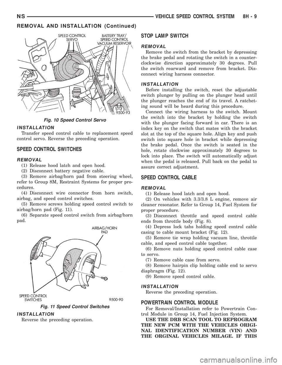
(5) Remove screws holding speed control switch to
airbag/horn pad (Fig. 11).
(6) Separate speed control switch from airbag/horn
pad.
INSTALLATION
Reverse the preceding operation.
STOP LAMP SWITCH
REMOVAL
Remove the switch from the bracket by depressing
the brake pedal and rotating the switch in a counter-
clockwise direction approximately 30 degrees. Pull
the switch rearward and remove from bracket. Dis-
connect wiring harness connector.
INSTALLATION
Before installing the switch, reset the adjustable
switch plunger by pulling on the plunger head until
the plunger reaches the end of its travel. A ratchet-
ing sound will be heard during this procedure.
Connect the wiring harness to the switch. Mount
the switch into the bracket by holding the switch
with the plunger facing forward in car. There is an
index key on the switch that mates with the bracket
slot at the top of the square hole. Align key and push
switch into square hole in bracket while depressing
the brake pedal. Once the switch is seated in the
hole, rotate clockwise approximately 30 degrees to
lock into place. The switch will automatically adjust
when the pedal is released. Pull back on the pedal to
assure correct adjustment.
SPEED CONTROL CABLE
REMOVAL
(1) Release hood latch and open hood.
(2) On vehicles with 3.3/3.8 L engine, remove air
cleaner resonator. Refer to Group 14, Fuel System for
proper procedure.
(3) Disconnect throttle and speed control cable
ends from throttle body (Fig. 8).
(4) Depress lock tabs holding speed control cable
casing to cable mount bracket (Fig. 12).
(5) Remove tie wrap holding vacuum line, throttle
cable, and speed control cable together.
(6) Remove nuts holding speed control cable case
to servo.
(7) Remove cable case from servo.
(8) Remove hairpin clip holding cable end to servo
diaphragm (Fig. 12).
(9) Remove speed control cable.
INSTALLATION
Reverse the preceding operation.
POWERTRAIN CONTROL MODULE
For Removal/Installation refer to Powertrain Con-
trol Module in Group 14, Fuel Injection System.
USE THE DRB SCAN TOOL TO REPROGRAM
THE NEW PCM WITH THE VEHICLES ORIGI-
NAL IDENTIFICATION NUMBER (VIN) AND
THE ORGINAL VEHICLES MILAGE. IF THIS
Fig. 10 Speed Control Servo
Fig. 11 Speed Control Switches
NSVEHICLE SPEED CONTROL SYSTEM 8H - 9
REMOVAL AND INSTALLATION (Continued)
Page 498 of 1938

ACM monitors the system to determine the system
readiness. The ACM contains on-board diagnostics
and will light the AIRBAG warning lamp in the mes-
sage center when a problem occurs.
The driver and passenger airbag system is a safety
device designed to reduce the risk of fatality or seri-
ous injury, caused by a frontal impact of the vehicle.
The impact sensor provides verification of the
direction and severity of the impact. One impact sen-
sor is used. It is located inside the Airbag Control
Module (ACM) which is mounted on a bracket, just
forward of the center console. The impact sensor is
an accelerometer that senses deceleration. The decel-
eration pulses are sent to a microprocessor which
contains a decision algorithm. When an impact is
severe enough to require airbag protection, the ACM
micro processor sends a signal that completes the
electrical circuit to the driver and passenger airbags.
The sensor is calibrated for the specific vehicle and
reacts to the severity and direction of the impact.
CLOCKSPRING
The clockspring is snapped into a plastic mounting
platform on the steering column behind the steering
wheel. The clockspring is used to maintain a contin-
uous electrical circuit between the wiring harness
and the driver's airbag module. This assembly con-
sists of a flat ribbon like electrically conductive tape
which winds and unwinds with the steering wheel
rotation.
DRIVER AND PASSENGER AIRBAG MODULES
The Driver Airbag Module is located in the center
of the steering wheel. The Passenger Airbag Module
is located in the instrument panel above the glove
box (Fig. 1). The Driver Airbag Module cover contains
the horn switch, inflator device, and a fabric bag. The
airbag cover/horn switch is serviced separately from
the inflator and bag components. Refer to Group 8G,
Horns for proper service procedure for horn switch.
The Passenger Airbag Module is serviced as an
assembly.
WARNING: WHEN THE AIRBAG SYSTEM IS
DEPLOYED BECAUSE OF A COLLISION, THE FOL-
LOWING MUST BE REPLACED:
²COMPLETE STEERING COLUMN ASSEMBLY
²LOWER STEERING COUPLER
²STEERING WHEEL
²STEERING COLUMN CLOCKSPRING
²DRIVER AIRBAG COVER/HORN SWITCH
²DRIVER AIRBAG MODULE
²PASSENGER AIRBAG MODULE
²UPPER INSTRUMENT PANEL WITH PAD
DIAGNOSIS AND TESTING
AIRBAG SYSTEM TEST
(1) Disconnect and isolate the battery negative
cable.
WARNING: DISCONNECT AND ISOLATE THE BAT-
TERY NEGATIVE CABLE BEFORE BEGINNING AIR-
BAG SYSTEM COMPONENT SERVICE
PROCEDURES. THIS WILL DISABLE THE AIRBAG
SYSTEM. FAILURE TO DISCONNECT THE BATTERY
COULD RESULT IN ACCIDENTAL AIRBAG DEPLOY-
MENT AND POSSIBLE PERSONAL INJURY. ALLOW
SYSTEM CAPACITOR TO DISCHARGE FOR TWO
MINUTES BEFORE REMOVING AIRBAG COMPO-
NENTS.
(2) Connect scan tool (DRB) to Data Link connec-
tor, located at left side of the steering column and at
the lower edge of the lower instrument panel.
(3) Turn the ignition key to ON position. Exit vehi-
cle with scan tool. Use the latest version of the
proper cartridge.
(4) After checking that no one is inside the vehicle,
connect the battery negative terminal.
(5) Using the scan tool, read and record active
diagnostic code data.
(6) Read and record any stored diagnostic codes.
(7) Refer to the proper Body Diagnostic Procedures
Manual if any diagnostic codes are found in Step 5 or
Step 6.
(8) Erase stored diagnostic codes if there are no
active diagnostic codes. If problems remain, diagnos-
tic codes will not erase. Refer to the Passive
Restraint Diagnostic Test Manual to diagnose the
problem.If airbag warning lamp either fails to
light, or goes on and stays on, there is a system
malfunction. Refer to the proper Body Diagnos-
tic Procedures Manual to diagnose the problem.
Fig. 1 Airbag Module Locations
8M - 2 RESTRAINT SYSTEMNS
DESCRIPTION AND OPERATION (Continued)
Page 509 of 1938

POWER DOOR LOCKS
CONTENTS
page page
POWER DOOR LOCKS..................... 1REMOTE KEYLESS ENTRY.................. 5
POWER DOOR LOCKS
INDEX
page page
GENERAL INFORMATION
INTRODUCTION......................... 1
DESCRIPTION AND OPERATION
AUTOMATIC DOOR LOCK FEATURE.......... 1
DOOR LOCK CIRCUIT PROTECTION......... 1
DOOR LOCK INHIBIT FEATURE............. 2
SLIDING DOOR LOCK MEMORY FEATURE..... 2
DIAGNOSIS AND TESTING
AUTOMATIC DOOR LOCK SYSTEM TEST...... 2
DOOR LOCK MOTOR..................... 2DOOR LOCK SWITCH TEST................ 2
SERVICE PROCEDURES
AUTOMATIC DOOR LOCKS
DISABLE OR ENABLE.................... 3
REMOVAL AND INSTALLATION
FRONT DOOR LOCK MOTOR/LATCH......... 3
LIFTGATE LOCK MOTOR................... 3
SLIDING DOOR LOCK CONTACTS........... 3
SLIDING DOOR LOCK MOTOR.............. 4
SLIDING DOOR LOCK PLUNGER............ 4
GENERAL INFORMATION
INTRODUCTION
The Body Control Module (BCM) locks or unlocks
the doors when an actuation input signal from a door
lock switch or Remote Keyless Entry Module (RKE)
is received. The BCM signals lock and unlock relays
in the Junction Block to actuate the door lock motors.
The front doors, sliding door(s) and liftgate are
equipped with actuator motors to lock or unlock the
latch mechanisms. The front door lock actuator motor
is not serviced separately from the door latch. The
BCM locks the doors and liftgate automatically when
the vehicle is driven beyond the speed of 25.7 Km/h
(16 mph). The automatic door lock feature can be dis-
abled if desired. All doors and liftgate can be locked
or unlocked using mechanical button or key cylinder
methods.
DESCRIPTION AND OPERATION
AUTOMATIC DOOR LOCK FEATURE
The vehicle comes with two options for power door
locks:
²Rolling automatic lock (ENABLE), doors auto-
matically lock at approximately at 25.7 Km/h (16
mph).
²No rolling automatic lock (DISABLE), doors do
not automatically lock when the vehicle is moving.
The BCM is equipped with a disable feature to
stop the speed sensitive automatic door locks from
functioning. The DISABLE feature can be switched
ON or OFF as desired. When the system is DIS-
ABLED the door locks will operate normally, but will
not lock automatically when the vehicle is rolling.
When the door locks are ENABLED the door locks
will automatically lock when the vehicle is moving at
about 25.7 Km/h (16 mph).
DOOR LOCK CIRCUIT PROTECTION
The BCM controls the door lock relay's operation.
If the door lock switch is actuated continuously for
more than one second the BCM will interrupt the
relay circuit. The door lock system is protected by a
40 amp fuse located in the Power Distribution Center
(PDC). The LOCK and UNLOCK relays are located
in the Junction Block. The Power Distribution Center
is located along side of the battery. The lock motors
are protected with Positive Temperature Coefficient
(PTC) device that prevents motor burn out.
NSPOWER DOOR LOCKS 8P - 1
Page 510 of 1938

DOOR LOCK INHIBIT FEATURE
The BCM cancels out the door lock switch actua-
tion, when the key is in the Ignition Switch and a
door is open. After the key is removed from the Igni-
tion Switch, or the doors are closed, the power door
locks will operate normally.
SLIDING DOOR LOCK MEMORY FEATURE
The door locks on the sliding door(s) can be actu-
ated when the door(s) are closed. If the sliding
door(s) are open when the door locks are actuated,
the BCM will hold the lock command in memory
until the door(s) is closed. When the door is closed
and the door jamb terminals make contact, signaling
the BCM to lock the sliding door(s) automatically.
Actuating the door lock switch to the unlock position
before the sliding door(s) are closed will cancel the
lock request.
DIAGNOSIS AND TESTING
AUTOMATIC DOOR LOCK SYSTEM TEST
When using a scan tool (DRB) for testing the auto-
matic door lock system, refer to the Body Diagnostic
Procedures Manual. Refer to Group 8W, Wiring Dia-
grams for circuit information and component loca-
tions.
DOOR LOCK MOTOR
Verify battery condition before testing door lock
motor(s), refer to Group 8A, Battery for proper diag-
nosis procedures.
To determine which motor is faulty, check each
individual door for electrical lock and unlock or dis-
connect the motor connectors one at a time, while
operating the door lock switch. In the event that
none of the motors work, the problem may be caused
by a shorted motor, a relay or a bad switch. Discon-
necting the defective motor will allow the others to
work.
To test an individual door lock motor, disconnect
the electrical connector from the motor. To lock the
door, connect a 12 volt power source to the positive
pin of the lock motor and a ground wire to the other
pin (Fig. 1), (Fig. 2), (Fig. 3) and refer to Group 8W,
Wiring Diagrams for pin locations. To unlock the door
reverse the wire connections at the motor pin termi-
nals. If these results are NOT obtained, replace the
motor.
DOOR LOCK SWITCH TEST
(1) Remove door lock switch bezel assembly from
door. Refer to Group 23, Body for removal proce-
dures.
(2) Disconnect wire connector from back of door
lock switch.(3) Depress switch to LOCK position.
(4) Using an ohmmeter, test switch resistance
between Pins 2 and 3. Refer to Door Lock Switch
Test and (Fig. 4).
(5) Depress switch to UNLOCK position.
(6) Test resistance between Pins 2 and 3.
(7) If resistance values are not within the param-
eters shown replace the door lock switch.
Fig. 1 Sliding Door Lock Motor±Typical
Fig. 2 Front Door Lock Motor
8P - 2 POWER DOOR LOCKSNS
DESCRIPTION AND OPERATION (Continued)
Page 513 of 1938
REMOTE KEYLESS ENTRY
INDEX
page page
DESCRIPTION AND OPERATION
INTRODUCTION......................... 5
VEHICLE ACCESS CODE (VAC)
PROGRAMMING........................ 5
DIAGNOSIS AND TESTING
RKE DIAGNOSTICS....................... 5
SERVICE PROCEDURES
HORN CHIRP DISABLE OR ENABLE.......... 6REMOVAL AND INSTALLATION
RKE MODULE........................... 6
ADJUSTMENTS
PROGRAMMING RKE MODULE.............. 6
SPECIFICATIONS
RKE TRANSMITTER BATTERY.............. 6
RKE TRANSMITTER RANGE................ 6
DESCRIPTION AND OPERATION
INTRODUCTION
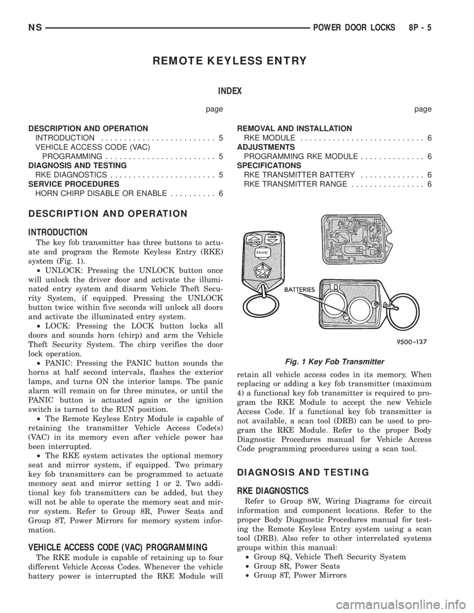
The key fob transmitter has three buttons to actu-
ate and program the Remote Keyless Entry (RKE)
system (Fig. 1).
²UNLOCK: Pressing the UNLOCK button once
will unlock the driver door and activate the illumi-
nated entry system and disarm Vehicle Theft Secu-
rity System, if equipped. Pressing the UNLOCK
button twice within five seconds will unlock all doors
and activate the illuminated entry system.
²LOCK: Pressing the LOCK button locks all
doors and sounds horn (chirp) and arm the Vehicle
Theft Security System. The chirp verifies the door
lock operation.
²PANIC: Pressing the PANIC button sounds the
horns at half second intervals, flashes the exterior
lamps, and turns ON the interior lamps. The panic
alarm will remain on for three minutes, or until the
PANIC button is actuated again or the ignition
switch is turned to the RUN position.
²The Remote Keyless Entry Module is capable of
retaining the transmitter Vehicle Access Code(s)
(VAC) in its memory even after vehicle power has
been interrupted.
²The RKE system activates the optional memory
seat and mirror system, if equipped. Two primary
key fob transmitters can be programmed to actuate
memory seat and mirror setting 1 or 2. Two addi-
tional key fob transmitters can be added, but they
will not be able to operate the memory seat and mir-
ror system. Refer to Group 8R, Power Seats and
Group 8T, Power Mirrors for memory system infor-
mation.
VEHICLE ACCESS CODE (VAC) PROGRAMMING
The RKE module is capable of retaining up to four
different Vehicle Access Codes. Whenever the vehicle
battery power is interrupted the RKE Module willretain all vehicle access codes in its memory. When
replacing or adding a key fob transmitter (maximum
4) a functional key fob transmitter is required to pro-
gram the RKE Module to accept the new Vehicle
Access Code. If a functional key fob transmitter is
not available, a scan tool (DRB) can be used to pro-
gram the RKE Module. Refer to the proper Body
Diagnostic Procedures manual for Vehicle Access
Code programming procedures using a scan tool.
DIAGNOSIS AND TESTING
RKE DIAGNOSTICS
Refer to Group 8W, Wiring Diagrams for circuit
information and component locations. Refer to the
proper Body Diagnostic Procedures manual for test-
ing the Remote Keyless Entry system using a scan
tool (DRB). Also refer to other interrelated systems
groups within this manual:
²Group 8Q, Vehicle Theft Security System
²Group 8R, Power Seats
²Group 8T, Power Mirrors
Fig. 1 Key Fob Transmitter
NSPOWER DOOR LOCKS 8P - 5