spark plugs replace CHRYSLER VOYAGER 1996 User Guide
[x] Cancel search | Manufacturer: CHRYSLER, Model Year: 1996, Model line: VOYAGER, Model: CHRYSLER VOYAGER 1996Pages: 1938, PDF Size: 55.84 MB
Page 326 of 1938
3.3/3.8L ENGINE
INDEX
page page
DESCRIPTION AND OPERATION
FIRING ORDERÐ3.3/3.8L................. 28
REMOVAL AND INSTALLATION
CAMSHAFT POSITION SENSOR............ 31
CRANKSHAFT POSITION SENSOR.......... 30
ENGINE COOLANT TEMPERATURE SENSOR . . 32
IGNITION COIL......................... 30
KNOCK SENSORÐ3.3/3.8L................ 32
MANIFOLD ABSOLUTE PRESSURE (MAP)
SENSOR............................. 32SPARK PLUG CABLE SERVICEÐ3.3/3.8L
ENGINES............................ 28
SPARK PLUG SERVICEÐ3.3/3.8L ENGINES . . . 29
THROTTLE POSITION SENSOR............ 32
SPECIFICATIONS
IGNITION COIL......................... 33
SPARK PLUG CABLE RESISTANCEÐ3.3/3.8L . . 34
SPARK PLUG........................... 33
TORQUE.............................. 34
DESCRIPTION AND OPERATION
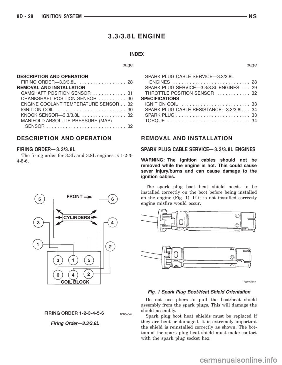
FIRING ORDERÐ3.3/3.8L
The firing order for 3.3L and 3.8L engines is 1-2-3-
4-5-6.
REMOVAL AND INSTALLATION
SPARK PLUG CABLE SERVICEÐ3.3/3.8L ENGINES
WARNING: The ignition cables should not be
removed while the engine is hot. This could cause
sever injury/burns and can cause damage to the
ignition cables.
The spark plug boot heat shield needs to be
installed correctly on the boot before being installed
on the engine (Fig. 1). If it is not installed correctly
engine misfire would occur.
Do not use pliers to pull the boot/heat shield
assembly from the spark plugs. This will damage the
shield assembly.
Spark plug boot heat shields must be replaced if
they are bent or damaged. It is extremely important
the shield is reinstalled correctly as shown. The bot-
tom of the spark plug heat shield must make contact
with the spark plug socket hex.
Firing OrderÐ3.3/3.8L
Fig. 1 Spark Plug Boot/Heat Shield Orientation
8D - 28 IGNITION SYSTEMNS
Page 1052 of 1938
made to seal the area between the bedplate and cyl-
inder block without disturbing the bearing clearance
or alignment of these components.
GASKET DISASSEMBLY
Parts assembled with form-in-place gaskets may be
disassembled without unusual effort. In some
instances, it may be necessary to lightly tap the part
with a mallet or other suitable tool to break the seal
between the mating surfaces. A flat gasket scraper
may also be lightly tapped into the joint but care
must be taken not to damage the mating surfaces.
SURFACE PREPARATION
Scrape clean or wire brush all gasket surfaces to
remove all loose material. Inspect stamped parts to
ensure gasket rails are flat. Gasket surfaces must be
free of oil and dirt. Make sure old gasket material is
removed from blind attaching holes.
FORM-IN-PLACE GASKET APPLICATION
Assembling parts using a form-in-place gasket
requires care but it's easier then using precut gas-
kets.
MopartGasket Maker material should be applied
sparingly 1 mm (0.040 in.) diameter or less of sealant
to one gasket surface. Be certain the material sur-
rounds each mounting hole. Excess material can eas-
ily be wiped off. Components should be torqued in
place within 15 minutes. The use of a locating dowel
is recommended during assembly to prevent smear-
ing the material off location.
TheMopartSilicone Rubber Adhesive Sealant
gasket material or equivalent should be applied in a
continuous bead approximately 3 mm (0.120 in.) in
diameter. All mounting holes must be circled. For
corner sealing, a 3.17 or 6.35 mm (1/8 or 1/4 in.) drop
is placed in the center of the gasket contact area.
Uncured sealant may be removed with a shop towels.
Components should be torqued in place while the
sealant is still wet to the touch (within 10 minutes).
The usage of a locating dowel is recommended during
assembly to prevent smearing of material off loca-
tion.
CRANKSHAFT SPROCKET BOLT ACCESS PLUG
An Access plug is located in the right inner fender
shield. Remove the plug and insert the proper size
socket, extension and ratchet, when crankshaft rota-
tion is necessary.
ENGINE CORE PLUGS
REMOVAL
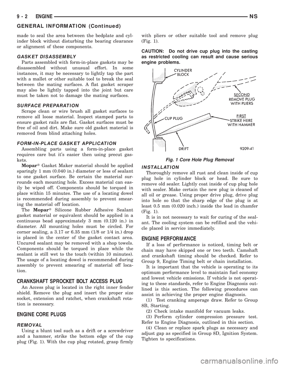
Using a blunt tool such as a drift or a screwdriver
and a hammer, strike the bottom edge of the cup
plug (Fig. 1). With the cup plug rotated, grasp firmlywith pliers or other suitable tool and remove plug
(Fig. 1).
CAUTION: Do not drive cup plug into the casting
as restricted cooling can result and cause serious
engine problems.
INSTALLATION
Thoroughly remove all rust and clean inside of cup
plug hole in cylinder block or head. Be sure to
remove old sealer. Lightly coat inside of cup plug hole
with sealer. Make certain the new plug is cleaned of
all oil or grease. Using proper drive plug, drive plug
into hole so that the sharp edge of the plug is at
least 0.5 mm (0.020 inch.) inside the lead in chamfer
(Fig. 1).
It is in not necessary to wait for curing of the seal-
ant. The cooling system can be refilled and the vehi-
cle placed in service immediately.
ENGINE PERFORMANCE
If a loss of performance is noticed, timing belt or
chain may have skipped one or two teeth. Camshaft
and crankshaft timing should be checked. Refer to
Group 9, Engine Timing belt or chain installation.
It is important that the vehicle is operating to its
optimum performance level to maintain fuel economy
and lowest vehicle emissions. If vehicle is not operat-
ing to these standards, refer to Engine Diagnosis out-
lined is this section. The following procedures can
assist in achieving the proper engine diagnosis.
(1) Test cranking amperage draw. Refer to Group
8B, Starting.
(2) Check intake manifold for vacuum leaks.
(3) Perform cylinder compression pressure test.
Refer to Engine Diagnosis, outlined in this section.
(4) Clean or replace spark plugs as necessary and
adjust gap as specified in Group 8D, Ignition System.
Tighten to specifications.
Fig. 1 Core Hole Plug Removal
9 - 2 ENGINENS
GENERAL INFORMATION (Continued)
Page 1058 of 1938
cause of low compression unless some malfunc-
tion is present.
(11) Clean or replace spark plugs as necessary
and adjust gap as specified in Group 8, Electrical.
Tighten to specifications.
(12) Test resistance of spark plug cables. Refer to
Group 8, Electrical Ignition System Secondary Cir-
cuit Inspection.
(13) Test coil output voltage, primary and second-
ary resistance. Replace parts as necessary. Refer to
Group 8, Electrical Ignition System.
(14) Check fuel pump pressure at idle and differ-
ent RPM ranges. Refer to Group 14, Fuel System for
Specifications.
(15) The air filter elements should be replaced as
specified in Group 0, Lubrication and Maintenance,.
(16) Inspect crankcase ventilation system as out
lined in Group 0, Lubrication and Maintenance. For
emission controls see Group 25, Emission Controls
for service procedures.
(17) Inspect and adjust accessory belt drives refer-
ring to Group 7, Cooling System, Accessory Drive
Belts for proper adjustments.
(18) Road test vehicle as a final test.
CYLINDER COMBUSTION PRESSURE LEAKAGE
TEST
The combustion pressure leakage test provides an
accurate means for determining engine condition.
Combustion pressure leakage testing will detect:
²Exhaust and intake valve leaks (improper seat-
ing).
²Leaks between adjacent cylinders or into water
jacket.
²Any causes for combustion/compression pressure
loss.
WARNING: DO NOT REMOVE THE RADIATOR CAP
WITH THE SYSTEM HOT AND UNDER PRESSURE
BECAUSE SERIOUS BURNS FROM COOLANT CAN
OCCUR.
Check the coolant level and fill as required. DO
NOT install the radiator cap.
Start and operate the engine until it attains nor-
mal operating temperature, then turn the engine
OFF.
Clean spark plug recesses with compressed air.
Remove the spark plugs.
Remove the oil filler cap.
Remove the air cleaner.
Calibrate the tester according to the manufactur-
er's instructions. The shop air source for testing
should maintain 483 kPa (70 psi) minimum, 1 379
kPa (200 psi) maximum and 552 kPa (80 psi) recom-
mended.Perform the test procedures on each cylinder
according to the tester manufacturer's instructions.
While testing, listen for pressurized air escaping
through the throttle body, tailpipe and oil filler cap
opening. Check for bubbles in the radiator coolant.
All gauge pressure indications should be equal,
with no more than 25% leakage.
FOR EXAMPLE:At 552 kPa (80 psi) input pres-
sure, a minimum of 414 kPa (60 psi) should be main-
tained in the cylinder.
LASH ADJUSTER (TAPPET) NOISE DIAGNOSIS
A tappet-like noise may be produced from several
items. Check the following items.
(1) Engine oil level too high or too low. This may
cause aerated oil to enter the adjusters and cause
them to be spongy.
(2) Insufficient running time after rebuilding cylin-
der head. Low speed running up to 1 hour may be
required.
(3) During this time, turn engine off and let set for
a few minutes before restarting. Repeat this several
times after engine has reached normal operating
temperature.
(4) Low oil pressure.
(5) The oil restrictor pressed into the vertical oil
passage to the cylinder head is plugged with debris.
(6) Air ingested into oil due to broken or cracked
oil pump pick up.
(7) Worn valve guides.
(8) Rocker arm ears contacting valve spring
retainer.
(9) Rocker arm loose, adjuster stuck or at maxi-
mum extension and still leaves lash in the system.
(10) Faulty lash adjuster.
a. Check lash adjusters for sponginess while
installed in cylinder head. Depress part of rocker
arm over adjuster. Normal adjusters should feel very
firm. Spongy adjusters can be bottomed out easily.
b. Remove suspected lash adjusters, and disassem-
bleDo not reuse retainer caps. Do not inter-
change parts and make sure that care and
cleanliness is exercised in the handling of parts.
c. Clean out dirt and varnish with solvent.
d. Reassemble with engine oil.
e. Check for sponginess.
f. If still spongy, replace with new adjuster.
INSPECTION (ENGINE OIL LEAKS IN GENERAL)
Begin with a through visual inspection of the
engine, particularly at the area of the suspected leak.
If an oil leak source is not readily identifiable, the
following steps should be followed:
(1) Do not clean or degrease the engine at this
time because some solvents may cause rubber to
swell, temporarily stopping the leak.
9 - 8 ENGINENS
DIAGNOSIS AND TESTING (Continued)
Page 1060 of 1938
ENGINE DIAGNOSISÐPERFORMANCE
CONDITION POSSIBLE CAUSE CORRECTION
ENGINE WILL NOT START 1. Weak battery. 1. Test battery. Charge or replace
as necessary.Refer to Group 8A,
Battery.
2. Corroded or loose battery
connections.2. Clean and tighten battery
connections. Apply a coat of light
mineral grease to terminals.
3. Faulty starter. Test starting system. Refer to Group
8B, Starting.
4. Moisture on ignition wires. 4. Remove moisture from wires.
5. Faulty ignition cables. 5. Replace any cracked or shorted
cables.
6. Faulty coil or control unit. 6. Test and replace as needed.
Refer to Group 8D, Ignition System
7. Incorrect spark plug gap. 7. Set gap. Refer to Group 8D,
Ignition System.
8. Contamination in fuel system. 8. Clean system and replace fuel
filter.
9. Faulty fuel pump. 9. Test fuel pump and replace as
needed. Refer to Group 14, Fuel
System.
ENGINE STALLS OR IDLES
ROUGH1. Idle speed too low. 1. Test minimum air flow. Refer to
Group 14, Fuel System.
2. Incorrect fuel mixture. 2. Refer to Group 14, Fuel System.
3. Intake manifold leakage. 3. Inspect intake manifold, manifold
gasket, and vacuum hoses. Refer to
Group 11, Exhaust System and
Intake Manifold.
4. Incorrect ignition wiring. 4. Install correct wiring.
5. Faulty coil(s) 5. Test and replace as necessary.
Refer to Group 8D, Ignition System.
ENGINE LOSS OF POWER 1. Dirty or incorrectly gapped plugs. 1. Clean plugs and set gap. Refer to
Group 8D, Ignition System.
2. Contamination in fuel system. 2. Clean system and replace fuel
filter.
3. Faulty fuel pump. 3. Test and replace as necessary.
Refer to Group 14, Fuel System.
4. Incorrect valve timing. 4. Correct valve timing.
5. Leaking cylinder head gasket. 5. Replace cylinder head gasket.
6. Low compression. 6. Test compression of each
cylinder.
7. Burned, warped, or pitted valves. 7. Replace valves.
8. Plugged or restricted exhaust
system.8. Install new parts, as necessary.
9. Faulty ignition cables. 9. Replace any cracked or shorted
cables.
10. Faulty coil(s). 10. Test and replace as necessary.
Refer to Group 8D, Ignition System.
9 - 10 ENGINENS
DIAGNOSIS AND TESTING (Continued)
Page 1061 of 1938
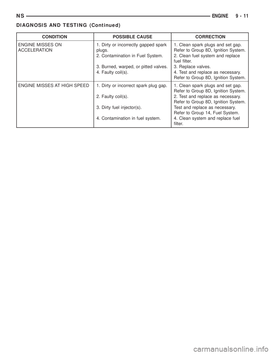
CONDITION POSSIBLE CAUSE CORRECTION
ENGINE MISSES ON
ACCELERATION1. Dirty or incorrectly gapped spark
plugs.1. Clean spark plugs and set gap.
Refer to Group 8D, Ignition System.
2. Contamination in Fuel System. 2. Clean fuel system and replace
fuel filter.
3. Burned, warped, or pitted valves. 3. Replace valves.
4. Faulty coil(s). 4. Test and replace as necessary.
Refer to Group 8D, Ignition System.
ENGINE MISSES AT HIGH SPEED 1. Dirty or incorrect spark plug gap. 1. Clean spark plugs and set gap.
Refer to Group 8D, Ignition System.
2. Faulty coil(s). 2. Test and replace as necessary.
Refer to Group 8D, Ignition System.
3. Dirty fuel injector(s). Test and replace as necessary.
Refer to Group 14, Fuel System.
4. Contamination in fuel system. 4. Clean system and replace fuel
filter.
NSENGINE 9 - 11
DIAGNOSIS AND TESTING (Continued)
Page 1063 of 1938
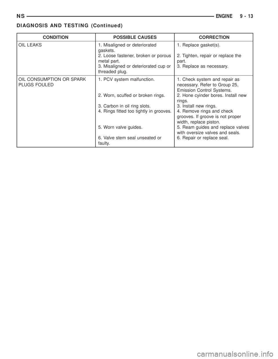
CONDITION POSSIBLE CAUSES CORRECTION
OIL LEAKS 1. Misaligned or deteriorated
gaskets.1. Replace gasket(s).
2. Loose fastener, broken or porous
metal part.2. Tighten, repair or replace the
part.
3. Misaligned or deteriorated cup or
threaded plug.3. Replace as necessary.
OIL CONSUMPTION OR SPARK
PLUGS FOULED1. PCV system malfunction. 1. Check system and repair as
necessary. Refer to Group 25,
Emission Control Systems.
2. Worn, scuffed or broken rings. 2. Hone cyinder bores. Install new
rings.
3. Carbon in oil ring slots. 3. Install new rings.
4. Rings fitted too tightly in grooves. 4. Remove rings and check
grooves. If groove is not proper
width, replace piston.
5. Worn valve guides. 5. Ream guides and replace valves
with oversize valves and seals.
6. Valve stem seal unseated or
faulty.6. Repair or replace seal.
NSENGINE 9 - 13
DIAGNOSIS AND TESTING (Continued)
Page 1157 of 1938
(4) Remove upper intake manifold. Refer to Group
11, Exhaust System and Intake Manifolds for proce-
dure.
(5) Remove cylinder head covers and spark plugs.
(6) Remove electrical connector from ignition coils.
(7) Using suitable socket and flex handle at crank-
shaft pulley retaining screw, turn engine so the num-
ber 1 piston is at Top Dead Center on the
compression stroke.
(8) Remove rocker arms with rocker shaft and
install a dummy shaft. The rocker arms should not
be disturbed and left on shaft.
(9) With air hose attached to spark plug adapter
installed in number 1 spark plug hole, apply 90 to
100 psi air pressure (620.5 to 689 kPa). This is to
hold valves in place while servicing components.
(10) Using Tool C-4682 or equivalent, compress
valve spring and remove retainer valve locks and
valve spring.
(11) The intake valve stem seals should be pushed
firmly and squarely over the valve guide using the
valve stem as guide.Do Not Forceseal against top
of guide. When installing the valve retainer locks,
compress the springonly enoughto install the
locks.
CAUTION: Do not pinch seal between retainer and
top of valve guide.
(12) Follow the same procedure on the remaining 5
cylinders using the firing sequence 1-2-3-4-5-6.Make
sure piston in cylinder is at TDC on the valve
spring that is being covered.
(13) Remove spark plug adapter tool.
(14) Remove dummy shaft and install rocker shaft
assembly and tighten screws to 28 N´m (250 in. lbs.).
(15) Install cylinder head covers tighten screws to
14 N´m (120 in. lbs.) and electrical connector to igni-
tion coils.
(16) Install Intake Manifold. Refer to Group 11,
Exhaust System and Intake Manifold for procedure.
(17) Connect negative cable to battery.
CYLINDER HEAD COVER
REMOVAL
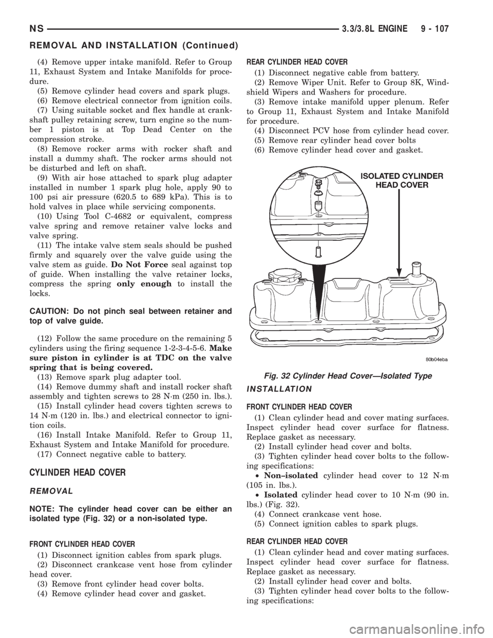
NOTE: The cylinder head cover can be either an
isolated type (Fig. 32) or a non-isolated type.
FRONT CYLINDER HEAD COVER
(1) Disconnect ignition cables from spark plugs.
(2) Disconnect crankcase vent hose from cylinder
head cover.
(3) Remove front cylinder head cover bolts.
(4) Remove cylinder head cover and gasket.REAR CYLINDER HEAD COVER
(1) Disconnect negative cable from battery.
(2) Remove Wiper Unit. Refer to Group 8K, Wind-
shield Wipers and Washers for procedure.
(3) Remove intake manifold upper plenum. Refer
to Group 11, Exhaust System and Intake Manifold
for procedure.
(4) Disconnect PCV hose from cylinder head cover.
(5) Remove rear cylinder head cover bolts
(6) Remove cylinder head cover and gasket.
INSTALLATION
FRONT CYLINDER HEAD COVER
(1) Clean cylinder head and cover mating surfaces.
Inspect cylinder head cover surface for flatness.
Replace gasket as necessary.
(2) Install cylinder head cover and bolts.
(3) Tighten cylinder head cover bolts to the follow-
ing specifications:
²Non±isolatedcylinder head cover to 12 N´m
(105 in. lbs.).
²Isolatedcylinder head cover to 10 N´m (90 in.
lbs.) (Fig. 32).
(4) Connect crankcase vent hose.
(5) Connect ignition cables to spark plugs.
REAR CYLINDER HEAD COVER
(1) Clean cylinder head and cover mating surfaces.
Inspect cylinder head cover surface for flatness.
Replace gasket as necessary.
(2) Install cylinder head cover and bolts.
(3) Tighten cylinder head cover bolts to the follow-
ing specifications:
Fig. 32 Cylinder Head CoverÐIsolated Type
NS3.3/3.8L ENGINE 9 - 107
REMOVAL AND INSTALLATION (Continued)
Page 1159 of 1938
(7) Inspect push rods and replace worn or bent
rods.
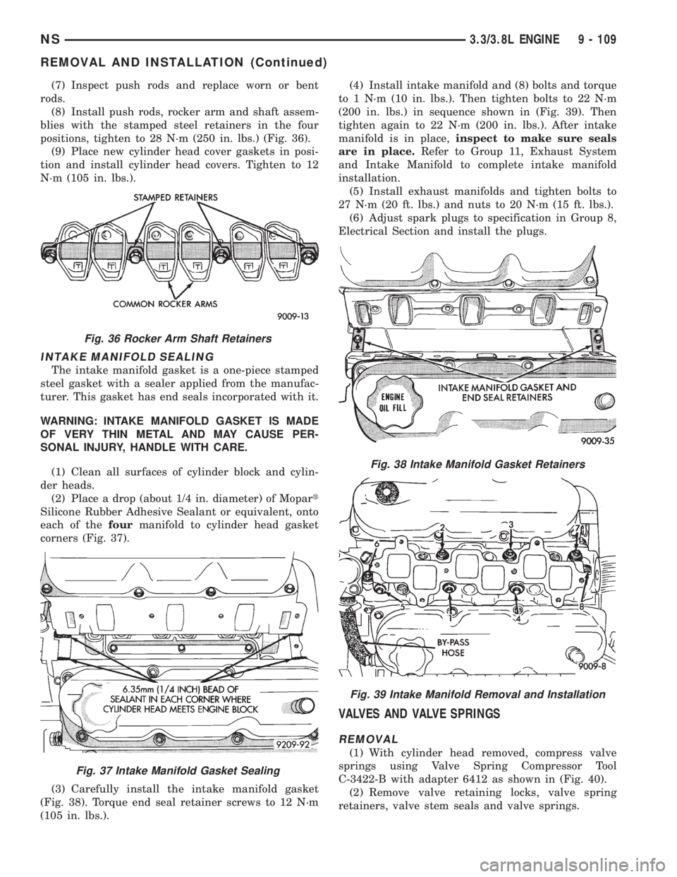
(8) Install push rods, rocker arm and shaft assem-
blies with the stamped steel retainers in the four
positions, tighten to 28 N´m (250 in. lbs.) (Fig. 36).
(9) Place new cylinder head cover gaskets in posi-
tion and install cylinder head covers. Tighten to 12
N´m (105 in. lbs.).
INTAKE MANIFOLD SEALING
The intake manifold gasket is a one-piece stamped
steel gasket with a sealer applied from the manufac-
turer. This gasket has end seals incorporated with it.
WARNING: INTAKE MANIFOLD GASKET IS MADE
OF VERY THIN METAL AND MAY CAUSE PER-
SONAL INJURY, HANDLE WITH CARE.
(1) Clean all surfaces of cylinder block and cylin-
der heads.
(2) Place a drop (about 1/4 in. diameter) of Mopart
Silicone Rubber Adhesive Sealant or equivalent, onto
each of thefourmanifold to cylinder head gasket
corners (Fig. 37).
(3) Carefully install the intake manifold gasket
(Fig. 38). Torque end seal retainer screws to 12 N´m
(105 in. lbs.).(4) Install intake manifold and (8) bolts and torque
to 1 N´m (10 in. lbs.). Then tighten bolts to 22 N´m
(200 in. lbs.) in sequence shown in (Fig. 39). Then
tighten again to 22 N´m (200 in. lbs.). After intake
manifold is in place,inspect to make sure seals
are in place.Refer to Group 11, Exhaust System
and Intake Manifold to complete intake manifold
installation.
(5) Install exhaust manifolds and tighten bolts to
27 N´m (20 ft. lbs.) and nuts to 20 N´m (15 ft. lbs.).
(6) Adjust spark plugs to specification in Group 8,
Electrical Section and install the plugs.
VALVES AND VALVE SPRINGS
REMOVAL
(1) With cylinder head removed, compress valve
springs using Valve Spring Compressor Tool
C-3422-B with adapter 6412 as shown in (Fig. 40).
(2) Remove valve retaining locks, valve spring
retainers, valve stem seals and valve springs.
Fig. 36 Rocker Arm Shaft Retainers
Fig. 37 Intake Manifold Gasket Sealing
Fig. 38 Intake Manifold Gasket Retainers
Fig. 39 Intake Manifold Removal and Installation
NS3.3/3.8L ENGINE 9 - 109
REMOVAL AND INSTALLATION (Continued)
Page 1263 of 1938
EXHAUST SYSTEM AND INTAKE MANIFOLD
CONTENTS
page page
GENERAL INFORMATION
CATALYTIC CONVERTERS................. 1
EXHAUST FLEX-JOINT COUPLING........... 2
EXHAUST GAS RECIRCULATION (EGR)....... 2
EXHAUST SYSTEM....................... 1
HEAT SHIELDS.......................... 2
DESCRIPTION AND OPERATION
INTAKE/EXHAUST MANIFOLDÐ2.4L ENGINE . . 3
INTAKE/EXHAUST MANIFOLDÐ3.0L ENGINE . . 3
INTAKE/EXHAUST MANIFOLDÐ3.3/3.8L
ENGINES............................. 3
DIAGNOSIS AND TESTING
EXHAUST SYSTEM....................... 3REMOVAL AND INSTALLATION
EXHAUST MANIFOLDÐ2.4L ENGINE........ 8
EXHAUST MANIFOLDÐ3.0L ENGINE....... 11
EXHAUST MANIFOLDSÐ3.3/3.8L ENGINE . . . 16
EXHAUST PIPES, MUFFLERS AND TAILPIPES . 4
INTAKE MANIFOLD LOWERÐ2.4L ENGINE.... 6
INTAKE MANIFOLDÐ3.0L ENGINE.......... 8
INTAKE MANIFOLDÐ3.3/3.8L ENGINE...... 12
UPPER INTAKE MANIFOLDÐ2.4L ENGINE.... 4
CLEANING AND INSPECTION
EXHAUST MANIFOLD.................... 17
INTAKE MANIFOLD...................... 17
SPECIFICATIONS
TORQUE CHART........................ 18
GENERAL INFORMATION
EXHAUST SYSTEM
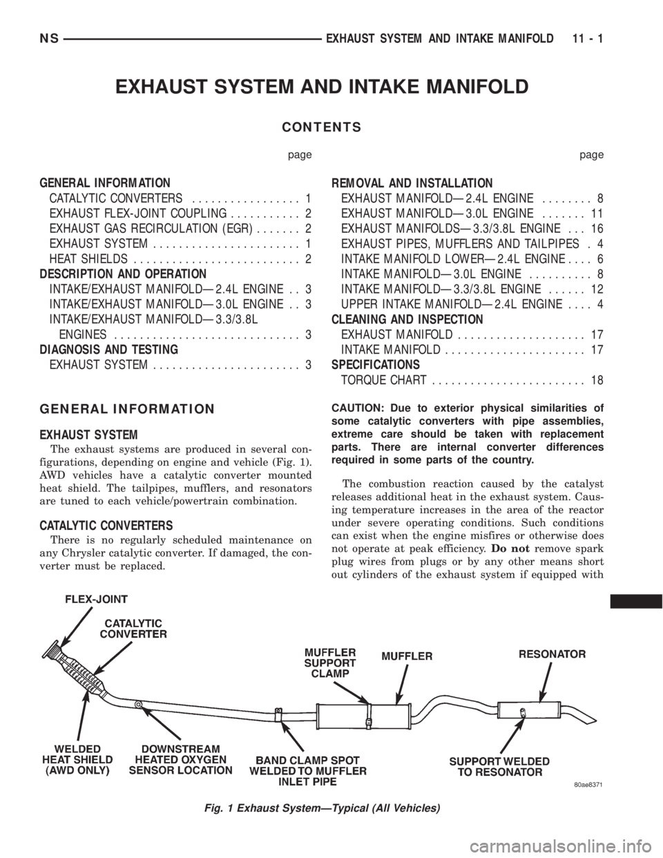
The exhaust systems are produced in several con-
figurations, depending on engine and vehicle (Fig. 1).
AWD vehicles have a catalytic converter mounted
heat shield. The tailpipes, mufflers, and resonators
are tuned to each vehicle/powertrain combination.
CATALYTIC CONVERTERS
There is no regularly scheduled maintenance on
any Chrysler catalytic converter. If damaged, the con-
verter must be replaced.CAUTION: Due to exterior physical similarities of
some catalytic converters with pipe assemblies,
extreme care should be taken with replacement
parts. There are internal converter differences
required in some parts of the country.
The combustion reaction caused by the catalyst
releases additional heat in the exhaust system. Caus-
ing temperature increases in the area of the reactor
under severe operating conditions. Such conditions
can exist when the engine misfires or otherwise does
not operate at peak efficiency.Do notremove spark
plug wires from plugs or by any other means short
out cylinders of the exhaust system if equipped with
Fig. 1 Exhaust SystemÐTypical (All Vehicles)
NSEXHAUST SYSTEM AND INTAKE MANIFOLD 11 - 1
Page 1381 of 1938
A defective fuel injection pump, defective fuel tim-
ing solenoid or misadjusted mechanical pump timing
can cause starting problems or prevent the engine
from revving up. It can also cause:
²Engine surge at idle
²Rough idle (warm engine)
²Low power
²Excessive fuel consumption
²Poor performance
²Low power
²Black smoke from the exhaust
²Blue or white fog like exhaust
²Incorrect idle or maximum speed
The electronically controlled fuel pump has no
mechanical governor like older mechanically con-
trolled fuel pumps. Do not remove the top cover of
the fuel pump, or the screws fastening the wiring
pigtail to the side of the pump.The warranty of
the injection pump and the engine may be void
if those seals have been removed or tampered
with.
FUEL SUPPLY RESTRICTIONS
LOW±PRESSURE LINES
Restricted or Plugged supply lines or fuel filter can
cause a timing fault that will cause the PCM to oper-
ate the engine in a ªLimp Homeº mode. See the
introduction of the Fuel Injection System in this
group for more information on the Limp Home mode.
Fuel supply line restrictions can cause starting prob-
lems and prevent the engine from revving up. The
starting problems include; low power and blue or
white fog like exhaust. Test all fuel supply lines for
restrictions or blockage. Flush or replace as neces-
sary. Bleed the fuel system of air once a fuel supply
line has been replaced. Refer to the Air Bleed Proce-
dure section of this group for procedures.
HIGH±PRESSURE LINES
Restricted (kinked or bent) high±pressure lines can
cause starting problems, poor engine performance
and black smoke from exhaust.
Examine all high±pressure lines for any damage.
Each radius on each high±pressure line must be
smooth and free of any bends or kinks.
Replace damaged, restricted or leaking high±pres-
sure fuel lines with the correct replacement line.
CAUTION: The high±pressure fuel lines must be
clamped securely in place in the holders. The lines
cannot contact each other or other components. Do
not attempt to weld high±pressure fuel lines or to
repair lines that are damaged. Only use the recom-
mended lines when replacement of high±pressure
fuel line is necessary.
FUEL SHUTDOWN SOLENOID TEST
Since diesel fuel injection does not use spark plugs
to start combustion, the only way to stop the engine
is to cut off the fuel supply. This is done with the
Fuel Shutdown Solenoid. If the engine cranks, but
refuses to start, it may be caused by a defective fuel
shutdown solenoid.
The fuel shutdown solenoid is not controlled
or operated by the PCM.Voltage to operate the
solenoid is supplied from the ignition (key) switch.
NOTE: Although the fuel shutdown solenoid is not
operated by the PCM, if the Fuel Shutdown Solenoid
has been disconnected, and the key turned on, the
PCM will sense that the solenoid is not in the circuit,
and will switch to a ªLimp Homeº mode. After recon-
necting the solenoid, the PCM will have to be reset
by clearing the codes with the DRBIII scan tool, or
disconnecting the vehicle's battery for several min-
utes. The DRBIII scan tool is the preferred method
for resetting the PCM. Refer to the 1998 GS 2.5L Die-
sel Powertrain Diagnostic Manual for procedure.
The fuel shutdown (shut±off) solenoid is used to
electrically shut off the diesel fuel supply to the high-
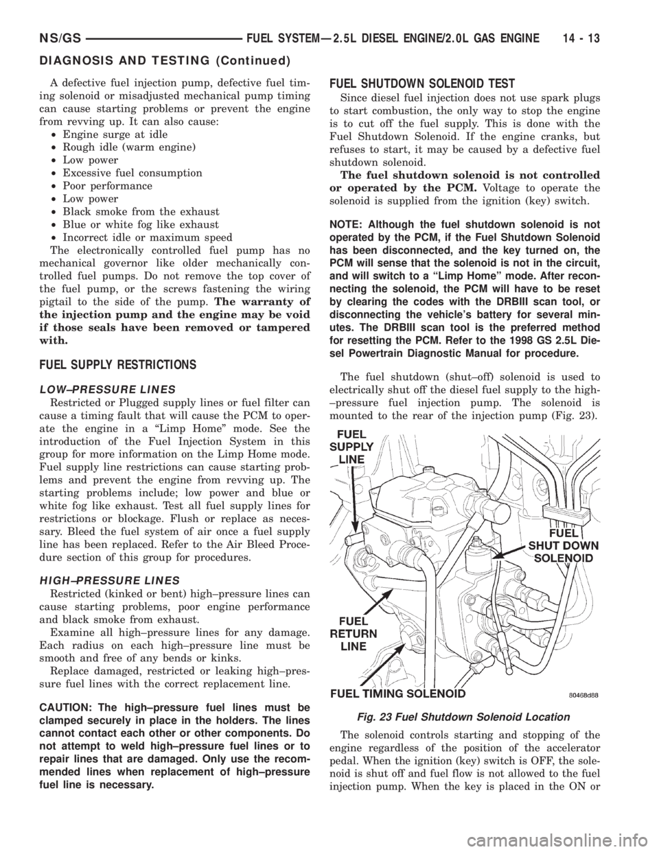
±pressure fuel injection pump. The solenoid is
mounted to the rear of the injection pump (Fig. 23).
The solenoid controls starting and stopping of the
engine regardless of the position of the accelerator
pedal. When the ignition (key) switch is OFF, the sole-
noid is shut off and fuel flow is not allowed to the fuel
injection pump. When the key is placed in the ON or
Fig. 23 Fuel Shutdown Solenoid Location
NS/GSFUEL SYSTEMÐ2.5L DIESEL ENGINE/2.0L GAS ENGINE 14 - 13
DIAGNOSIS AND TESTING (Continued)