relay CHRYSLER VOYAGER 1996 Service Manual
[x] Cancel search | Manufacturer: CHRYSLER, Model Year: 1996, Model line: VOYAGER, Model: CHRYSLER VOYAGER 1996Pages: 1938, PDF Size: 55.84 MB
Page 1315 of 1938
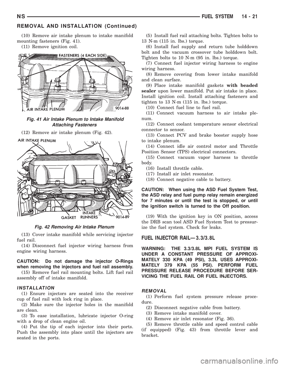
(10) Remove air intake plenum to intake manifold
mounting fasteners (Fig. 41).
(11) Remove ignition coil.
(12) Remove air intake plenum (Fig. 42).
(13) Cover intake manifold while servicing injector
fuel rail.
(14) Disconnect fuel injector wiring harness from
engine wiring harness.
CAUTION: Do not damage the injector O-Rings
when removing the injectors and fuel rail assembly.
(15) Remove fuel rail mounting bolts. Lift fuel rail
assembly off of intake manifold.
INSTALLATION
(1) Ensure injectors are seated into the receiver
cup of fuel rail with lock ring in place.
(2) Make sure the injector holes in the manifold
are clean.
(3) To ease installation, lubricate injector O-ring
with a drop of clean engine oil.
(4) Put the tip of each injector into their ports.
Push the assembly into place until the injectors are
seated in the ports.(5) Install fuel rail attaching bolts. Tighten bolts to
13 N´m (115 in. lbs.) torque.
(6) Install fuel supply and return tube holddown
bolt and the vacuum crossover tube holddown bolt.
Tighten bolts to 10 N´m (95 in. lbs.) torque.
(7) Connect fuel injector wiring harness to engine
wiring harness.
(8) Remove covering from lower intake manifold
and clean surface.
(9) Place intake manifold gasketswith beaded
sealerupon lower manifold. Put air intake in place.
Install ignition coil. Install attaching fasteners and
tighten to 13 N´m (115 in. lbs.) torque.
(10) Connect fuel line to fuel rail.
(11) Connect vacuum harness to air intake ple-
num.
(12) Connect coolant temperature sensor electrical
connector to sensor.
(13) Connect PCV and brake booster supply hose
to intake plenum.
(14) Connect idle air control motor and Throttle
Position Sensor (TPS) electrical connectors.
(15) Connect vacuum vapor harness to throttle
body.
(16) Install throttle cable.
(17) Install air inlet resonator.
(18) Connect negative cable to battery.
CAUTION: When using the ASD Fuel System Test,
the ASD relay and fuel pump relay remain energized
for 7 minutes or until the test is stopped, or until
the ignition switch is turned to the Off position.
(19) With the ignition key in ON position, access
the DRB scan tool ASD Fuel System Test to pressur-
ize the fuel system. Check for leaks.
FUEL INJECTOR RAILÐ3.3/3.8L
WARNING: THE 3.3/3.8L MPI FUEL SYSTEM IS
UNDER A CONSTANT PRESSURE OF APPROXI-
MATELY 330 KPA (49 PSI), 3.3L USES APPROXI-
MATELY 379 KPA (55 PSI). PERFORM FUEL
PRESSURE RELEASE PROCEDURE BEFORE SER-
VICING THE FUEL RAIL OR FUEL INJECTORS.
REMOVAL
(1) Perform fuel system pressure release proce-
dure.
(2) Disconnect negative cable from battery.
(3) Remove intake manifold cover.
(4) Remove air inlet resonator (Fig. 36).
(5) Remove throttle cable and speed control cable
(if equipped) (Fig. 43) from throttle lever and
bracket.
Fig. 41 Air Intake Plenum to Intake Manifold
Attaching Fasteners
Fig. 42 Removing Air Intake Plenum
NSFUEL SYSTEM 14 - 21
REMOVAL AND INSTALLATION (Continued)
Page 1318 of 1938
(4) Install the fuel rail mounting bolts. Tighten
bolts to 22 N´m (200 in. lbs.) torque (Fig. 51).
(5) Install fuel tube retaining bracket screw.
Tighten screw to 4 N´m (35 in. lbs.) torque.
(6) Connect electrical connectors to camshaft posi-
tion sensor and engine coolant temperature sensor.
(7) Remove covering on lower intake manifold and
clean surface.
(8) Place intake manifold gasket on lower mani-
fold. Put upper manifold into place and install bolts
finger tight.
(9) Install the generator bracket to intake mani-
fold bolt and the cylinder head to intake manifold
strut bolts (do not tighten.)(10) Following the tightening sequence in (Fig. 50),
tighten intake manifold bolts to 28 N´m (250 in. lbs.)
torque.
(11) Tighten generator bracket to intake manifold
bolt to 54 N´m (40 ft. lbs.) torque.
(12) Tighten the cylinder head to intake manifold
strut bolts to 54 N´m (40 ft. lbs.) torque.
(13) Connect ground strap and MAP sensor electri-
cal connector.
(14) Connect vacuum harness to intake plenum.
Connect PCV system hoses.
(15) Using a new gasket, connect the EGR tube to
the intake manifold plenum. Tighten screws to 22
N´m (200 in. lbs.) torque.
(16) Connect electrical connectors to the TPS and
idle air control motor.
(17) Connect vacuum harness to throttle body.
(18) Install the direct ignition system (DIS) coils.
Tighten fasteners to 12 N´m (105 in. lbs.) torque.
(19) Install fuel hose quick connector fitting to
chassis tubes.Refer to Fuel Hoses, Clamps and
Quick Connect Fittings in this Section.Push the
fitting onto the chassis tube until it clicks into place.
Pull on the fitting to ensure complete insertion.
(20) Install throttle cable and speed control cable
(if equipped).
(21) Install air inlet resonator.
(22) Connect negative cable to battery.
CAUTION: When using the ASD Fuel System Test,
the ASD relay and fuel pump relay remain energized
for 7 minutes or until the test is stopped, or until
the ignition switch is turned to the Off position.
(23) With the ignition key in ON position, access
the DRB scan tool ASD Fuel System Test to pressur-
ize the fuel system. Check for leaks.
FUEL INJECTORÐ2.4L
The fuel rail must be removed first. Refer to Fuel
Injector Rail Removal in this section.
REMOVAL
(1) Disconnect injector wiring connector from injec-
tor.
(2) Position fuel rail assembly so that the fuel
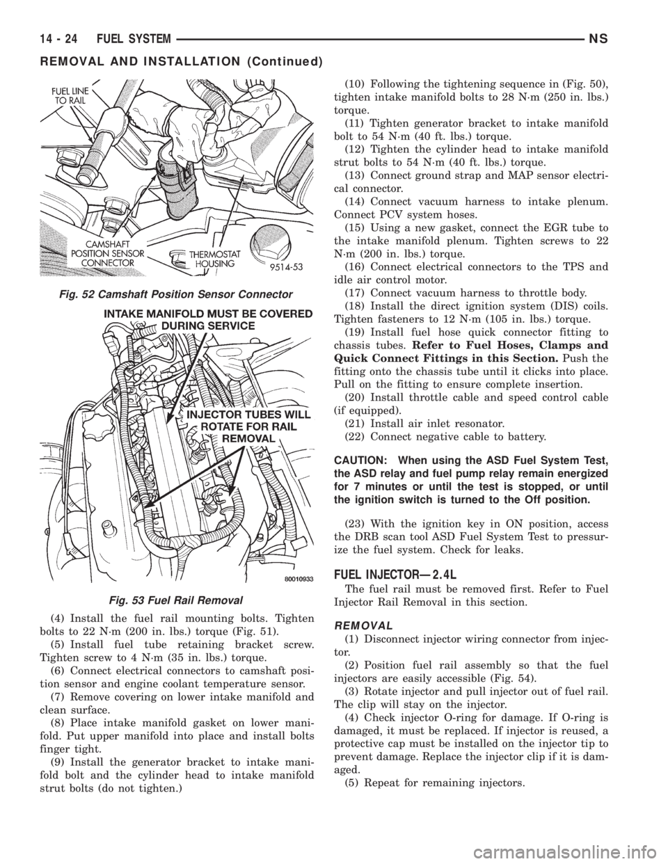
injectors are easily accessible (Fig. 54).
(3) Rotate injector and pull injector out of fuel rail.
The clip will stay on the injector.
(4) Check injector O-ring for damage. If O-ring is
damaged, it must be replaced. If injector is reused, a
protective cap must be installed on the injector tip to
prevent damage. Replace the injector clip if it is dam-
aged.
(5) Repeat for remaining injectors.
Fig. 52 Camshaft Position Sensor Connector
Fig. 53 Fuel Rail Removal
14 - 24 FUEL SYSTEMNS
REMOVAL AND INSTALLATION (Continued)
Page 1319 of 1938
INSTALLATION
(1) Before installing an injector the rubber O-ring
must be lubricated with a drop of clean engine oil to
aid in installation.
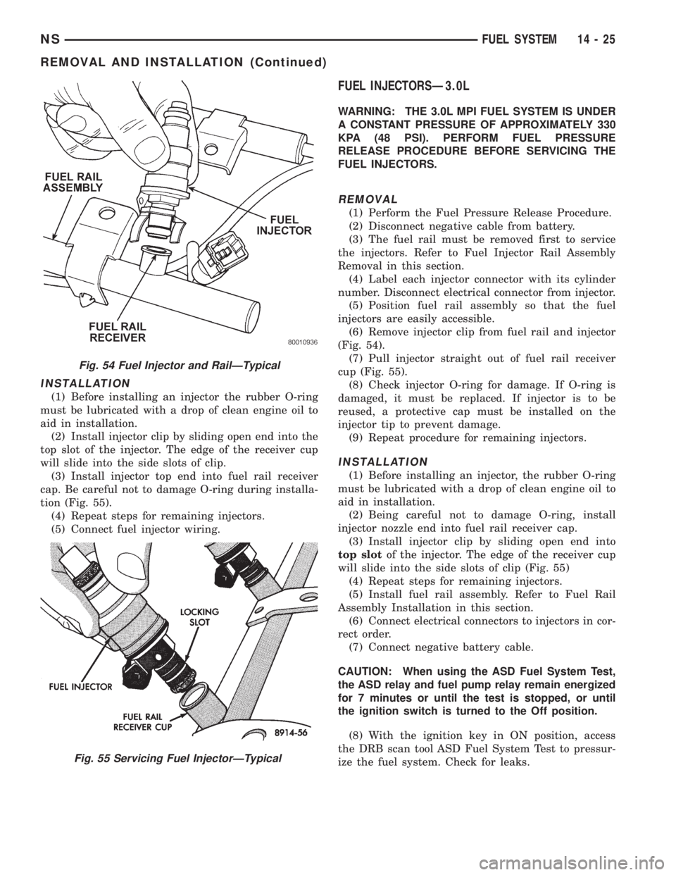
(2) Install injector clip by sliding open end into the
top slot of the injector. The edge of the receiver cup
will slide into the side slots of clip.
(3) Install injector top end into fuel rail receiver
cap. Be careful not to damage O-ring during installa-
tion (Fig. 55).
(4) Repeat steps for remaining injectors.
(5) Connect fuel injector wiring.
FUEL INJECTORSÐ3.0L
WARNING: THE 3.0L MPI FUEL SYSTEM IS UNDER
A CONSTANT PRESSURE OF APPROXIMATELY 330
KPA (48 PSI). PERFORM FUEL PRESSURE
RELEASE PROCEDURE BEFORE SERVICING THE
FUEL INJECTORS.
REMOVAL
(1) Perform the Fuel Pressure Release Procedure.
(2) Disconnect negative cable from battery.
(3) The fuel rail must be removed first to service
the injectors. Refer to Fuel Injector Rail Assembly
Removal in this section.
(4) Label each injector connector with its cylinder
number. Disconnect electrical connector from injector.
(5) Position fuel rail assembly so that the fuel
injectors are easily accessible.
(6) Remove injector clip from fuel rail and injector
(Fig. 54).
(7) Pull injector straight out of fuel rail receiver
cup (Fig. 55).
(8) Check injector O-ring for damage. If O-ring is
damaged, it must be replaced. If injector is to be
reused, a protective cap must be installed on the
injector tip to prevent damage.
(9) Repeat procedure for remaining injectors.
INSTALLATION
(1) Before installing an injector, the rubber O-ring
must be lubricated with a drop of clean engine oil to
aid in installation.
(2) Being careful not to damage O-ring, install
injector nozzle end into fuel rail receiver cap.
(3) Install injector clip by sliding open end into
top slotof the injector. The edge of the receiver cup
will slide into the side slots of clip (Fig. 55)
(4) Repeat steps for remaining injectors.
(5) Install fuel rail assembly. Refer to Fuel Rail
Assembly Installation in this section.
(6) Connect electrical connectors to injectors in cor-
rect order.
(7) Connect negative battery cable.
CAUTION: When using the ASD Fuel System Test,
the ASD relay and fuel pump relay remain energized
for 7 minutes or until the test is stopped, or until
the ignition switch is turned to the Off position.
(8) With the ignition key in ON position, access
the DRB scan tool ASD Fuel System Test to pressur-
ize the fuel system. Check for leaks.
Fig. 54 Fuel Injector and RailÐTypical
Fig. 55 Servicing Fuel InjectorÐTypical
NSFUEL SYSTEM 14 - 25
REMOVAL AND INSTALLATION (Continued)
Page 1323 of 1938
FUEL INJECTION SYSTEM
INDEX
page page
GENERAL INFORMATION
INTRODUCTION......................... 30
MODES OF OPERATION.................. 30
DESCRIPTION AND OPERATION
AIR CONDITIONING (A/C) CLUTCH RELAYÐ
PCM OUTPUT......................... 41
AIR CONDITIONING PRESSURE
TRANSDUCERÐPCM INPUT............. 33
AIR CONDITIONING SWITCH SENSEÐ
PCM INPUT........................... 33
AUTOMATIC SHUTDOWN (ASD) SENSEÐ
PCM INPUT........................... 33
AUTOMATIC SHUTDOWN RELAYÐPCM
OUTPUT............................. 42
AUTOMATIC TRANSAXLE CONTROL
MODULEÐPCM OUTPUT................ 44
BATTERY VOLTAGEÐPCM INPUT........... 33
BRAKE SWITCHÐPCM INPUT.............. 33
CAMSHAFT POSITION SENSORÐPCM INPUT . 33
CCDBUS .............................. 32
CRANKSHAFT POSITION SENSORÐPCM
INPUT............................... 35
DATA LINK CONNECTORÐPCM OUTPUT..... 44
DUTY CYCLE EVAP CANISTER PURGE
SOLENOIDÐPCM OUTPUT.............. 43
ELECTRONIC EGR TRANSDUCER
SOLENOIDÐPCM OUTPUT.............. 43
ENGINE COOLANT TEMPERATURE SENSORÐ
PCM INPUT........................... 36
FUEL INJECTORSÐPCM OUTPUT.......... 44
FUEL PUMP RELAYÐPCM OUTPUT......... 42
GENERATOR FIELDÐPCM OUTPUT......... 42
HEATED OXYGEN SENSOR (O2S SENSOR)Ð
PCM INPUT........................... 37
IDLE AIR CONTROL MOTORÐPCM OUTPUT . . 42
IGNITION COILÐPCM OUTPUT............. 45
INTAKE AIR TEMPERATURE SENSORÐPCM
INPUT (2.4L ONLY)..................... 41
KNOCK SENSORÐPCM INPUT............. 38
MALFUNCTION INDICATOR (CHECK ENGINE)
LAMPÐPCM OUTPUT.................. 46
MANIFOLD ABSOLUTE PRESSURE (MAP)
SENSORÐPCM INPUT.................. 39
POWERTRAIN CONTROL MODULE (PCM).... 32
PROPORTIONAL PURGE SOLENOID......... 43
SOLID STATE FAN RELAYÐPCM OUTPUT.... 46
SPEED CONTROL SOLENOIDSÐ
PCM OUTPUT......................... 46
SPEED CONTROLÐPCM INPUT............ 39STARTER RELAYÐPCM OUTPUT........... 42
SYSTEM DIAGNOSIS..................... 32
TACHOMETERÐPCM OUTPUT............. 47
THROTTLE BODY....................... 47
THROTTLE POSITION SENSOR (TPS)Ð
PCM INPUT........................... 40
TORQUE CONVERTER CLUTCH SOLENOIDÐ
PCM OUTPUT......................... 46
TRANSAXLE PARK/NEUTRAL SWITCHÐ
PCM INPUT........................... 40
VEHICLE SPEED AND DISTANCEÐ
PCM INPUT........................... 41
DIAGNOSIS AND TESTING
ASD AND FUEL PUMP RELAYS............. 59
CAMSHAFT AND CRANKSHAFT POSITION
SENSOR............................. 61
ENGINE COOLANT TEMPERATURE SENSOR . . 61
HEATED OXYGEN SENSOR............... 61
KNOCK SENSOR........................ 61
MANIFOLD ABSOLUTE PRESSURE (MAP)
SENSOR............................. 60
THROTTLE BODY MINIMUM AIR FLOW
CHECK PROCEDURE................... 62
THROTTLE POSITION SENSOR............ 62
VISUAL INSPECTIONÐ2.4L ENGINE......... 47
VISUAL INSPECTIONÐ3.0L ENGINE......... 52
VISUAL INSPECTIONÐ3.3/3.8L ENGINES..... 55
REMOVAL AND INSTALLATION
AIR CLEANER ELEMENT.................. 70
AUTOMATIC SHUTDOWN (ASD) RELAY...... 64
CAMSHAFT POSITION SENSOR............ 68
CRANKSHAFT POSITION SENSOR.......... 68
DOWNSTREAM OXYGEN SENSOR.......... 69
ENGINE COOLANT TEMPERATURE
SENSORÐ2.4L........................ 70
ENGINE COOLANT TEMPERATURE
SENSORÐ3.0L........................ 71
ENGINE COOLANT TEMPERATURE
SENSORÐ3.3/3.8L..................... 71
FUEL PUMP RELAY...................... 64
IDLE AIR CONTROL MOTOR............... 65
INTAKE AIR TEMPERATURE SENSORÐ2.4L . . . 72
KNOCK SENSOR........................ 70
MANIFOLD ABSOLUTE PRESSURE (MAP)
SENSORÐ2.4/3.3/3.8L.................. 66
MANIFOLD ABSOLUTE PRESSURE (MAP)
SENSORÐ3.0L........................ 66
POWERTRAIN CONTROL MODULE.......... 67
PROPORTIONAL PURGE SOLENOID VALVE . . . 66
NSFUEL SYSTEM 14 - 29
Page 1324 of 1938
THROTTLE BODY....................... 64
THROTTLE POSITION SENSOR............ 65
UPSTREAM OXYGEN SENSOR............. 68
SPECIFICATIONS
TORQUE.............................. 72SPECIAL TOOLS
FUEL................................. 72
GENERAL INFORMATION
INTRODUCTION
All engines used in this section have a sequential
Multi-Port Electronic Fuel Injection system. The MPI
system is computer regulated and provides precise
air/fuel ratios for all driving conditions. The Power-
train Control Module (PCM) operates the fuel injec-
tion system.
The PCM regulates:
²Ignition timing
²Air/fuel ratio
²Emission control devices
²Cooling fan
²Charging system
²Idle speed
²Vehicle speed control
Various sensors provide the inputs necessary for
the PCM to correctly operate these systems. In addi-
tion to the sensors, various switches also provide
inputs to the PCM.
All inputs to the PCM are converted into signals.
The PCM can adapt its programming to meet chang-
ing operating conditions.
Fuel is injected into the intake port above the
intake valve in precise metered amounts through
electrically operated injectors. The PCM fires the
injectors in a specific sequence. Under most operat-
ing conditions, the PCM maintains an air fuel ratio
of 14.7 parts air to 1 part fuel by constantly adjust-
ing injector pulse width. Injector pulse width is the
length of time the injector is open.
The PCM adjusts injector pulse width by opening
and closing the ground path to the injector. Engine
RPM (speed) and manifold absolute pressure (air
density) are the primary inputs that determine injec-
tor pulse width.
MODES OF OPERATION
As input signals to the PCM change, the PCM
adjusts its response to output devices. For example,
the PCM must calculate a different injector pulse
width and ignition timing for idle than it does for
Wide Open Throttle (WOT). There are several differ-
ent modes of operation that determine how the PCM
responds to the various input signals.
There are two different areas of operation, OPEN
LOOP and CLOSED LOOP.
During OPEN LOOP modes the PCM receives
input signals and responds according to preset PCMprogramming. Input from the oxygen (O2S) sensor is
not monitored during OPEN LOOP modes.
During CLOSED LOOP modes the PCM does mon-
itor the O2S sensor input. This input indicates to the
PCM whether or not the calculated injector pulse
width results in the ideal air/fuel ratio of 14.7 parts
air to 1 part fuel. By monitoring the exhaust oxygen
content through the O2S sensor, the PCM can fine
tune the injector pulse width. Fine tuning injector
pulse width allows the PCM to achieve optimum fuel
economy combined with low emissions.
The multi-port fuel injection system has the follow-
ing modes of operation:
²Ignition switch ON (zero RPM)
²Engine start-up
²Engine warm-up
²Cruise (Idle)
²Acceleration
²Deceleration
²Wide Open Throttle
²Ignition switch OFF
The engine start-up (crank), engine warm-up, and
wide open throttle modes are OPEN LOOP modes.
Under most operating conditions, the acceleration,
deceleration, and cruise modes,with the engine at
operating temperatureare CLOSED LOOP modes.
IGNITION SWITCH ON (ZERO RPM) MODE
When the multi-port fuel injection system is acti-
vated by the ignition switch, the following actions
occur:
²The PCM determines atmospheric air pressure
from the MAP sensor input to determine basic fuel
strategy.
²The PCM monitors the coolant temperature sen-
sor and throttle position sensor input. The PCM mod-
ifies fuel strategy based on this input.
When the key is in the ON position and the engine
is not running (zero rpm), the Automatic Shutdown
(ASD) relay and fuel pump relay are not energized.
Therefore battery voltage is not supplied to the fuel
pump, ignition coil, fuel injectors or oxygen sensor
heating element.
ENGINE START-UP MODE
This is an OPEN LOOP mode. The following
actions occur when the starter motor is engaged.
If the PCM receives the camshaft position sensor
and crankshaft position sensor signals, it energizes
the ASD relay and fuel pump relay. These relays sup-
ply battery voltage to the fuel pump, fuel injectors,
14 - 30 FUEL SYSTEMNS
SPECIFICATIONS (Continued)
Page 1325 of 1938
ignition coil, and oxygen sensor heating element. If
the PCM does not receive the camshaft position sen-
sor and crankshaft position sensor signals within
approximately one second, it de-energizes the ASD
relay and fuel pump relay.
The PCM energizes all injectors until it determines
crankshaft position from the camshaft position sen-
sor and crankshaft position sensor signals. The PCM
determines crankshaft position within 1 engine revo-
lution.
After determining crankshaft position, the PCM
begins energizing the injectors in sequence. The PCM
adjusts injector pulse width and controls injector syn-
chronization by turning the individual ground paths
to the injectors On and Off.
When the engine idles within664 RPM of its tar-
get RPM, the PCM compares current MAP sensor
value with the atmospheric pressure value received
during the Ignition Switch On (zero RPM) mode. If
the PCM does not detect a minimum difference
between the two values, it sets a MAP diagnostic
trouble code into memory.
Once the ASD and fuel pump relays have been
energized, the PCM:
²Determines injector pulse width based on engine
coolant temperature, MAP and the number of engine
revolutions since cranking was initiated.
²Monitors the engine coolant temperature sensor,
camshaft position sensor, crankshaft position sensor,
MAP sensor, and throttle position sensor to deter-
mine correct ignition timing.
ENGINE WARM-UP MODE
This is a OPEN LOOP mode. The following inputs
are received by the PCM:
²Engine coolant temperature
²Manifold absolute pressure
²Engine speed (crankshaft position sensor)
²Throttle position
²A/C switch
²Battery voltage
The PCM adjusts injector pulse width and controls
injector synchronization by turning the individual
ground paths to the injectors On and Off.
The PCM adjusts ignition timing and engine idle
speed. Engine idle speed is adjusted through the idle
air control motor.
CRUISE OR IDLE MODE
This is a CLOSED LOOP mode. The PCM recog-
nizes an abrupt increase in throttle position or MAP
pressure as a demand for increased engine output
and vehicle acceleration. The PCM increases injector
pulse width in response to increased fuel demand.
When the engine is at operating temperature this
is a CLOSED LOOP mode. During cruising speed the
following inputs are received by the PCM:²Engine coolant temperature
²Manifold absolute pressure
²Engine speed (crankshaft position sensor)
²Throttle position
²Exhaust gas oxygen content
²A/C control positions
²Battery voltage
The PCM adjusts injector pulse width and controls
injector synchronization by turning the individual
ground paths to the injectors On and Off.
The PCM adjusts engine idle speed and ignition
timing. The PCM adjusts the air/fuel ratio according
to the oxygen content in the exhaust gas.
ACCELERATION MODE
This is a CLOSED LOOP mode. The PCM recog-
nizes an abrupt increase in throttle position or MAP
pressure as a demand for increased engine output
and vehicle acceleration. The PCM increases injector
pulse width in response to increased fuel demand.
DECELERATION MODE
This is a CLOSED LOOP mode. During decelera-
tion the following inputs are received by the PCM:
²Engine coolant temperature
²Manifold absolute pressure
²Engine speed
²Throttle position
²Exhaust gas oxygen content
²A/C control positions
²Battery voltage
The PCM may receive a closed throttle input from
the Throttle Position Sensor (TPS) when it senses an
abrupt decrease in manifold pressure. This indicates
a hard deceleration. The PCM may reduce injector
pulse width or the number of injectors firing per
engine revolution. This helps maintain better control
of the air/fuel mixture (as sensed through the O2S
sensor).
WIDE OPEN THROTTLE (WOT) MODE
This is an OPEN LOOP mode. During WOT oper-
ation, the following inputs are received by the PCM:
²Engine coolant temperature
²Manifold absolute pressure
²Engine speed
²Throttle position
When the PCM senses WOT condition through the
Throttle Position Sensor (TPS) it will:
²De-energize the air conditioning relay. This dis-
ables the air conditioning system.
The exhaust gas oxygen content input is not
accepted by the PCM during WOT operation. The
PCM will adjust injector pulse width to supply a pre-
determined amount of additional fuel.
NSFUEL SYSTEM 14 - 31
GENERAL INFORMATION (Continued)
Page 1326 of 1938
IGNITION SWITCH OFF MODE
When the ignition switch is turned to the OFF
position, the following occurs:
²All outputs are turned off.
²No inputs are monitored.
²The PCM shuts down.
DESCRIPTION AND OPERATION
SYSTEM DIAGNOSIS
The PCM can test many of its own input and out-
put circuits. If the PCM senses a fault in a major
system, the PCM stores a Diagnostic Trouble Code
(DTC) in memory.
For DTC information, refer to Group 25, Emission
Control Systems. See On-Board Diagnostics.
CCD BUS
Various controllers and modules exchange informa-
tion through a communications port called the CCD
Bus. The PCM transmits the malfunction indicator
(check engine) lamp On/Off signal, engine RPM and
vehicle load information on the CCD Bus.
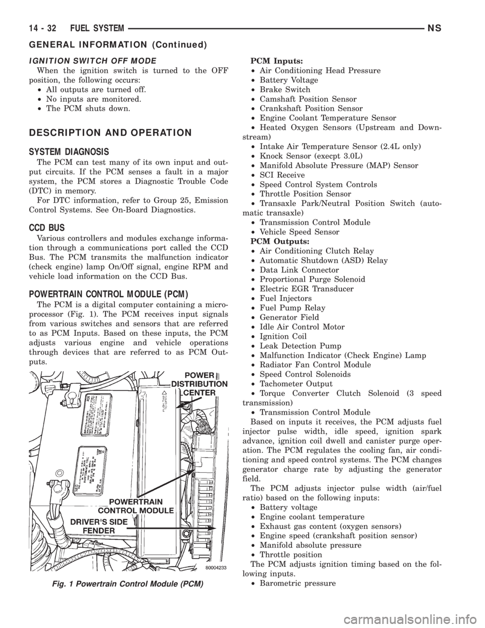
POWERTRAIN CONTROL MODULE (PCM)
The PCM is a digital computer containing a micro-
processor (Fig. 1). The PCM receives input signals
from various switches and sensors that are referred
to as PCM Inputs. Based on these inputs, the PCM
adjusts various engine and vehicle operations
through devices that are referred to as PCM Out-
puts.PCM Inputs:
²Air Conditioning Head Pressure
²Battery Voltage
²Brake Switch
²Camshaft Position Sensor
²Crankshaft Position Sensor
²Engine Coolant Temperature Sensor
²Heated Oxygen Sensors (Upstream and Down-
stream)
²Intake Air Temperature Sensor (2.4L only)
²Knock Sensor (execpt 3.0L)
²Manifold Absolute Pressure (MAP) Sensor
²SCI Receive
²Speed Control System Controls
²Throttle Position Sensor
²Transaxle Park/Neutral Position Switch (auto-
matic transaxle)
²Transmission Control Module
²Vehicle Speed Sensor
PCM Outputs:
²Air Conditioning Clutch Relay
²Automatic Shutdown (ASD) Relay
²Data Link Connector
²Proportional Purge Solenoid
²Electric EGR Transducer
²Fuel Injectors
²Fuel Pump Relay
²Generator Field
²Idle Air Control Motor
²Ignition Coil
²Leak Detection Pump
²Malfunction Indicator (Check Engine) Lamp
²Radiator Fan Control Module
²Speed Control Solenoids
²Tachometer Output
²Torque Converter Clutch Solenoid (3 speed
transmission)
²Transmission Control Module
Based on inputs it receives, the PCM adjusts fuel
injector pulse width, idle speed, ignition spark
advance, ignition coil dwell and canister purge oper-
ation. The PCM regulates the cooling fan, air condi-
tioning and speed control systems. The PCM changes
generator charge rate by adjusting the generator
field.
The PCM adjusts injector pulse width (air/fuel
ratio) based on the following inputs:
²Battery voltage
²Engine coolant temperature
²Exhaust gas content (oxygen sensors)
²Engine speed (crankshaft position sensor)
²Manifold absolute pressure
²Throttle position
The PCM adjusts ignition timing based on the fol-
lowing inputs.
²Barometric pressure
Fig. 1 Powertrain Control Module (PCM)
14 - 32 FUEL SYSTEMNS
GENERAL INFORMATION (Continued)
Page 1327 of 1938
²Engine coolant temperature
²Engine speed (crankshaft position sensor)
²Intake air temperature (2.4L only)
²Manifold absolute pressure
²Throttle position
²Transaxle gear selection (park/neutral switch)
The PCM also adjusts engine idle speed through
the idle air control motor based on the following
inputs.
²Air conditioning select switch head pressure
²Brake switch
²Engine coolant temperature
²Engine speed (crankshaft position sensor)
²Manifold absolute pressure
²Throttle position
²Transaxle gear selection (park/neutral switch)
²Vehicle distance (speed)
The Automatic Shutdown (ASD) and fuel pump
relays are located in the Power Distribution Center
(PDC).
The camshaft position sensor (distributor pick-up
signal 3.0L) and crankshaft position sensor signals
are sent to the PCM. If the PCM does not receive
both signals within approximately one second of
engine cranking, it deactivates the ASD relay and
fuel pump relay. When these relays are deactivated,
power is shut off to the fuel injectors, ignition coil,
oxygen sensor heating element and fuel pump.
The PCM contains a voltage converter that
changes battery voltage to a regulated 8.0 volts to
power the camshaft position sensor, crankshaft posi-
tion sensor and vehicle speed sensor. The PCM also
provides a 5.0 volt supply for the manifold absolute
pressure sensor, throttle position sensor and engine
coolant temperature sensor.
AIR CONDITIONING PRESSURE TRANSDUCERÐ
PCM INPUT
The Powertrain Control Module (PCM) monitors
the A/C compressor discharge (high side) pressure
through the air conditioning pressure transducer.
The transducer supplies an input to the PCM. The
PCM engages the A/C compressor clutch if pressure
is sufficient for A/C system operation.
AIR CONDITIONING SWITCH SENSEÐPCM INPUT
When the air conditioning or defrost switch is put
in the ON position and the low pressure switch, com-
bination valve, and high pressure switch close, the
PCM receives an A/C input. After receiving this
input, the PCM activates the A/C compressor clutch
by grounding the A/C clutch relay. The PCM also
adjusts idle speed to a scheduled RPM to compensate
for increased engine load.
AUTOMATIC SHUTDOWN (ASD) SENSEÐPCM
INPUT
The ASD sense circuit informs the PCM when the
ASD relay energizes. A 12 volt signal at this input
indicates to the PCM that the ASD has been acti-
vated. This input is used only to sense that the ASD
relay is energized.
When energized, the ASD relay supplies battery
voltage to the fuel injectors, ignition coils and the
heating element in each oxygen sensor. If the PCM
does not receive 12 volts from this input after
grounding the ASD relay, it sets a Diagnostic Trouble
Code (DTC).
BATTERY VOLTAGEÐPCM INPUT
The PCM monitors the battery voltage input to
determine fuel injector pulse width and generator
field control.
If battery voltage is low the PCM will increase
injector pulse width (period of time that the injector
is energized).
BRAKE SWITCHÐPCM INPUT
When the brake switch is activated, the PCM
receives an input indicating that the brakes are
being applied. After receiving this input the PCM
maintains idle speed to a scheduled RPM through
control of the idle air control motor. The brake switch
is mounted on the brake pedal support bracket.
CAMSHAFT POSITION SENSORÐPCM INPUT
The PCM determines fuel injection synchronization
and cylinder identification from inputs provided by
the camshaft position sensor and crankshaft position
sensor. From the two inputs, the PCM determines
crankshaft position.
3.3/3.8L
The sensor generates pulses as groups of notches
on the camshaft sprocket pass underneath it (Fig. 2).
The PCM keeps track of crankshaft rotation and
identifies each cylinder by the pulses generated by
the notches on the camshaft sprocket. Four crank-
shaft pulses follow each group of camshaft pulses.
When the PCM receives two camshaft pulses fol-
lowed by the long flat spot on the camshaft sprocket,
it knows that the crankshaft timing marks for cylin-
der one are next (on driveplate). When the PCM
receives one camshaft pulse after the long flat spot
on the sprocket, cylinder number two crankshaft tim-
ing marks are next. After 3 camshaft pulses, the
PCM knows cylinder four crankshaft timing marks
follow. One camshaft pulse after the three pulses
indicates cylinder five. The two camshaft pulses after
cylinder 5 signals cylinder six (Fig. 3). The PCM can
synchronize on cylinders 1 or 4.
NSFUEL SYSTEM 14 - 33
DESCRIPTION AND OPERATION (Continued)
Page 1332 of 1938
system to enter into closed loop operation sooner.
Also, it allows the system to remain in closed loop
operation during periods of extended idle.
In Closed Loop operation the PCM monitors the
O2S input (along with other inputs) and adjusts the
injector pulse width accordingly. During Open Loop
operation the PCM ignores the O2 sensor input. The
PCM adjusts injector pulse width based on prepro-
grammed (fixed) values and inputs from other sen-
sors.
The Automatic Shutdown (ASD) relay supplies bat-
tery voltage to both the upstream and downstream
heated oxygen sensors. The oxygen sensors are
equipped with a heating element. The heating ele-
ments reduce the time required for the sensors to
reach operating temperature.
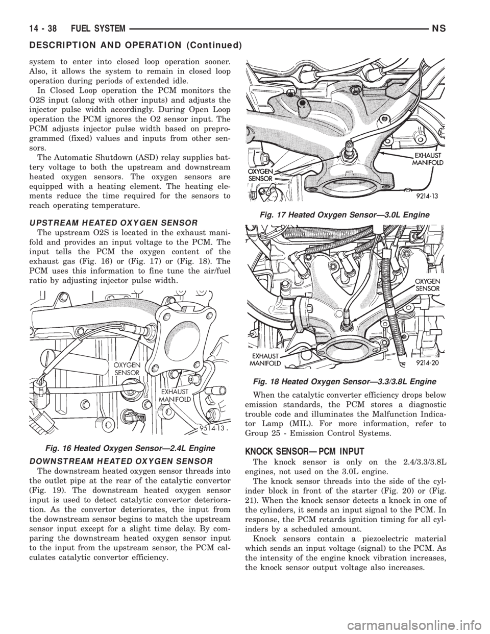
UPSTREAM HEATED OXYGEN SENSOR
The upstream O2S is located in the exhaust mani-
fold and provides an input voltage to the PCM. The
input tells the PCM the oxygen content of the
exhaust gas (Fig. 16) or (Fig. 17) or (Fig. 18). The
PCM uses this information to fine tune the air/fuel
ratio by adjusting injector pulse width.
DOWNSTREAM HEATED OXYGEN SENSOR
The downstream heated oxygen sensor threads into
the outlet pipe at the rear of the catalytic convertor
(Fig. 19). The downstream heated oxygen sensor
input is used to detect catalytic convertor deteriora-
tion. As the convertor deteriorates, the input from
the downstream sensor begins to match the upstream
sensor input except for a slight time delay. By com-
paring the downstream heated oxygen sensor input
to the input from the upstream sensor, the PCM cal-
culates catalytic convertor efficiency.When the catalytic converter efficiency drops below
emission standards, the PCM stores a diagnostic
trouble code and illuminates the Malfunction Indica-
tor Lamp (MIL). For more information, refer to
Group 25 - Emission Control Systems.
KNOCK SENSORÐPCM INPUT
The knock sensor is only on the 2.4/3.3/3.8L
engines, not used on the 3.0L engine.
The knock sensor threads into the side of the cyl-
inder block in front of the starter (Fig. 20) or (Fig.
21). When the knock sensor detects a knock in one of
the cylinders, it sends an input signal to the PCM. In
response, the PCM retards ignition timing for all cyl-
inders by a scheduled amount.
Knock sensors contain a piezoelectric material
which sends an input voltage (signal) to the PCM. As
the intensity of the engine knock vibration increases,
the knock sensor output voltage also increases.
Fig. 16 Heated Oxygen SensorÐ2.4L Engine
Fig. 17 Heated Oxygen SensorÐ3.0L Engine
Fig. 18 Heated Oxygen SensorÐ3.3/3.8L Engine
14 - 38 FUEL SYSTEMNS
DESCRIPTION AND OPERATION (Continued)
Page 1335 of 1938
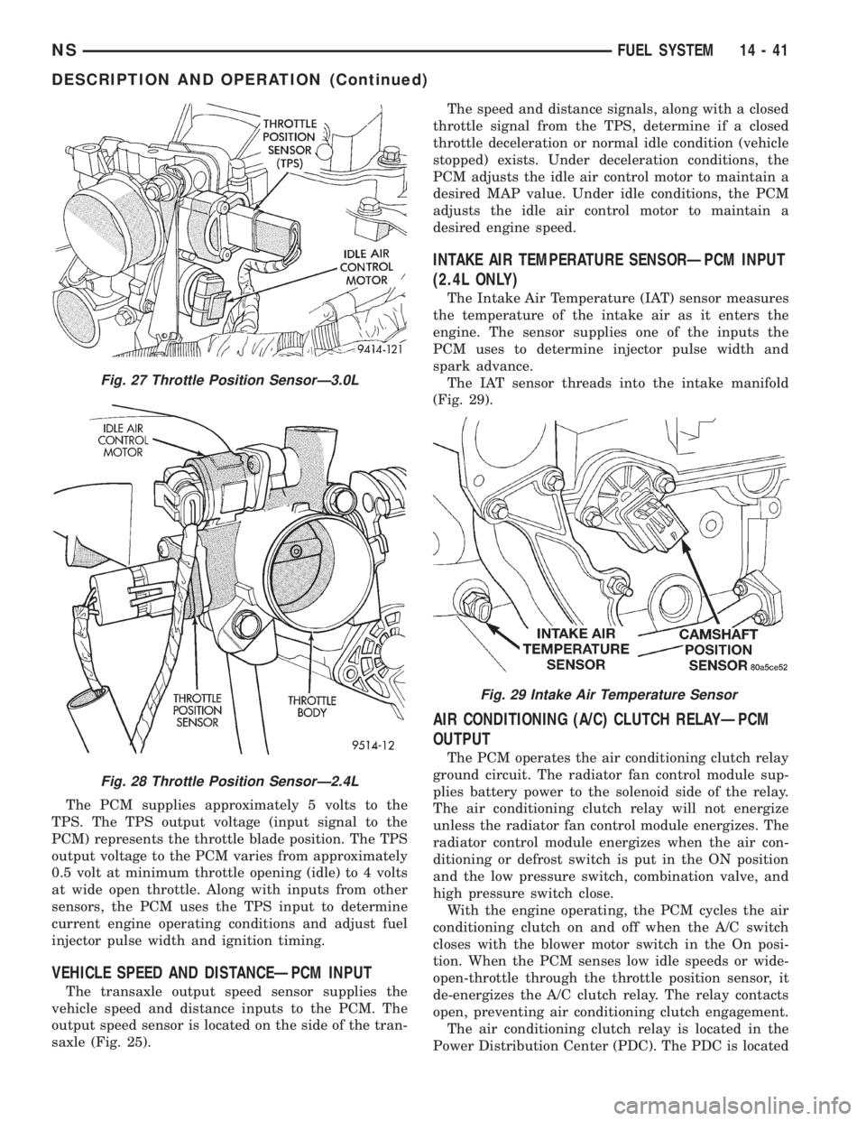
The PCM supplies approximately 5 volts to the
TPS. The TPS output voltage (input signal to the
PCM) represents the throttle blade position. The TPS
output voltage to the PCM varies from approximately
0.5 volt at minimum throttle opening (idle) to 4 volts
at wide open throttle. Along with inputs from other
sensors, the PCM uses the TPS input to determine
current engine operating conditions and adjust fuel
injector pulse width and ignition timing.
VEHICLE SPEED AND DISTANCEÐPCM INPUT
The transaxle output speed sensor supplies the
vehicle speed and distance inputs to the PCM. The
output speed sensor is located on the side of the tran-
saxle (Fig. 25).The speed and distance signals, along with a closed
throttle signal from the TPS, determine if a closed
throttle deceleration or normal idle condition (vehicle
stopped) exists. Under deceleration conditions, the
PCM adjusts the idle air control motor to maintain a
desired MAP value. Under idle conditions, the PCM
adjusts the idle air control motor to maintain a
desired engine speed.
INTAKE AIR TEMPERATURE SENSORÐPCM INPUT
(2.4L ONLY)
The Intake Air Temperature (IAT) sensor measures
the temperature of the intake air as it enters the
engine. The sensor supplies one of the inputs the
PCM uses to determine injector pulse width and
spark advance.
The IAT sensor threads into the intake manifold
(Fig. 29).
AIR CONDITIONING (A/C) CLUTCH RELAYÐPCM
OUTPUT
The PCM operates the air conditioning clutch relay
ground circuit. The radiator fan control module sup-
plies battery power to the solenoid side of the relay.
The air conditioning clutch relay will not energize
unless the radiator fan control module energizes. The
radiator control module energizes when the air con-
ditioning or defrost switch is put in the ON position
and the low pressure switch, combination valve, and
high pressure switch close.
With the engine operating, the PCM cycles the air
conditioning clutch on and off when the A/C switch
closes with the blower motor switch in the On posi-
tion. When the PCM senses low idle speeds or wide-
open-throttle through the throttle position sensor, it
de-energizes the A/C clutch relay. The relay contacts
open, preventing air conditioning clutch engagement.
The air conditioning clutch relay is located in the
Power Distribution Center (PDC). The PDC is located
Fig. 27 Throttle Position SensorÐ3.0L
Fig. 28 Throttle Position SensorÐ2.4L
Fig. 29 Intake Air Temperature Sensor
NSFUEL SYSTEM 14 - 41
DESCRIPTION AND OPERATION (Continued)