relay CHRYSLER VOYAGER 1996 Service Manual
[x] Cancel search | Manufacturer: CHRYSLER, Model Year: 1996, Model line: VOYAGER, Model: CHRYSLER VOYAGER 1996Pages: 1938, PDF Size: 55.84 MB
Page 1371 of 1938
FUEL DELIVERY SYSTEMÐ2.5L DIESEL ENGINE
INDEX
page page
DESCRIPTION AND OPERATION
FUEL DRAIN TUBES..................... 7
FUEL FILTER/WATER SEPARATOR.......... 4
FUEL GAUGE SENDING UNIT.............. 4
FUEL HEATER RELAY.................... 8
FUEL HEATER.......................... 8
FUEL INJECTION PUMP.................. 5
FUEL INJECTORS....................... 6
FUEL SHUTDOWN SOLENOID............. 5
FUEL SYSTEM PRESSURE WARNING....... 3
FUEL TANK MODULE.................... 4
FUEL TANK............................ 3
FUEL TUBES/LINES/HOSES AND CLAMPSÐ
LOW-PRESSURE TYPE................. 6
HIGH-PRESSURE FUEL LINES............. 7
INTRODUCTION........................ 3
QUICK-CONNECT FITTINGSÐLOW PRESSURE
TYPE............................... 7
WASTEGATE (TURBOCHARGER)........... 8
DIAGNOSIS AND TESTING
AIR IN FUEL SYSTEM................... 11
FUEL HEATER RELAY TEST.............. 12
FUEL INJECTION PUMP TEST............. 12
FUEL INJECTOR SENSOR TEST........... 12
FUEL INJECTOR TEST.................. 12
FUEL SHUTDOWN SOLENOID TEST........ 13
FUEL SUPPLY RESTRICTIONS............ 13GENERAL INFORMATION................. 9
HIGH-PRESSURE FUEL LINE LEAK TEST.... 14
VISUAL INSPECTION..................... 9
WASTEGATE (TURBOCHARGER).......... 14
SERVICE PROCEDURES
AIR BLEED PROCEDURES............... 14
FUEL INJECTION PUMP TIMING........... 15
REMOVAL AND INSTALLATION
ACCELERATOR PEDAL.................. 16
AIR CLEANER ELEMENT................. 16
FUEL DRAIN TUBES.................... 16
FUEL FILTER/WATER SEPARATOR......... 16
FUEL HEATER RELAY................... 17
FUEL HEATER......................... 17
FUEL INJECTION PUMP................. 19
FUEL INJECTORS...................... 22
FUEL LEVEL SENSOR................... 18
FUEL RESERVOIR MODULE.............. 25
FUEL SHUTDOWN SOLENOID............ 23
FUEL TANK........................... 23
HIGH-PRESSURE LINES................. 26
SPECIFICATIONS
FUEL INJECTOR FIRING SEQUENCE....... 27
FUEL SYSTEM PRESSURE............... 27
FUEL TANK CAPACITY.................. 27
IDLE SPEED.......................... 27
DESCRIPTION AND OPERATION
INTRODUCTION
This Fuel Delivery section will cover components
not controlled by the PCM. For components con-
trolled by the PCM, refer to the Fuel Injection Sys-
temÐ2.5L Diesel Engine section of this group.
The fuel heater relay, fuel heater and fuel gauge
are not operated by the PCM. These components are
controlled by the ignition (key) switch. All other fuel
system electrical components necessary to operate
the engine are controlled or regulated by the PCM.
FUEL SYSTEM PRESSURE WARNING
WARNING: HIGH±PRESSURE FUEL LINES DELIVER
DIESEL FUEL UNDER EXTREME PRESSURE FROM
THE INJECTION PUMP TO THE FUEL INJECTORS.
THIS MAY BE AS HIGH AS 45,000 KPA (6526 PSI).
USE EXTREME CAUTION WHEN INSPECTING FORHIGH±PRESSURE FUEL LEAKS. INSPECT FOR
HIGH±PRESSURE FUEL LEAKS WITH A SHEET OF
CARDBOARD (Fig. 1). HIGH FUEL INJECTION
PRESSURE CAN CAUSE PERSONAL INJURY IF
CONTACT IS MADE WITH THE SKIN.
FUEL TANK
The fuel tank and tank mounting used with the
diesel powered engine is the same as used with gas-
oline powered models, although the fuel tank module
is different.
The fuel tank contains the fuel tank module and
two rollover valves. Two fuel lines are routed to the
fuel tank module. One line is used for fuel supply to
the fuel filter/water separator. The other is used to
return excess fuel back to the fuel tank.
The fuel tank module contains the fuel gauge elec-
trical sending unit.An electrical fuel pump is not
used with the diesel engine.
NS/GSFUEL SYSTEMÐ2.5L DIESEL ENGINE/2.0L GAS ENGINE 14 - 3
Page 1376 of 1938
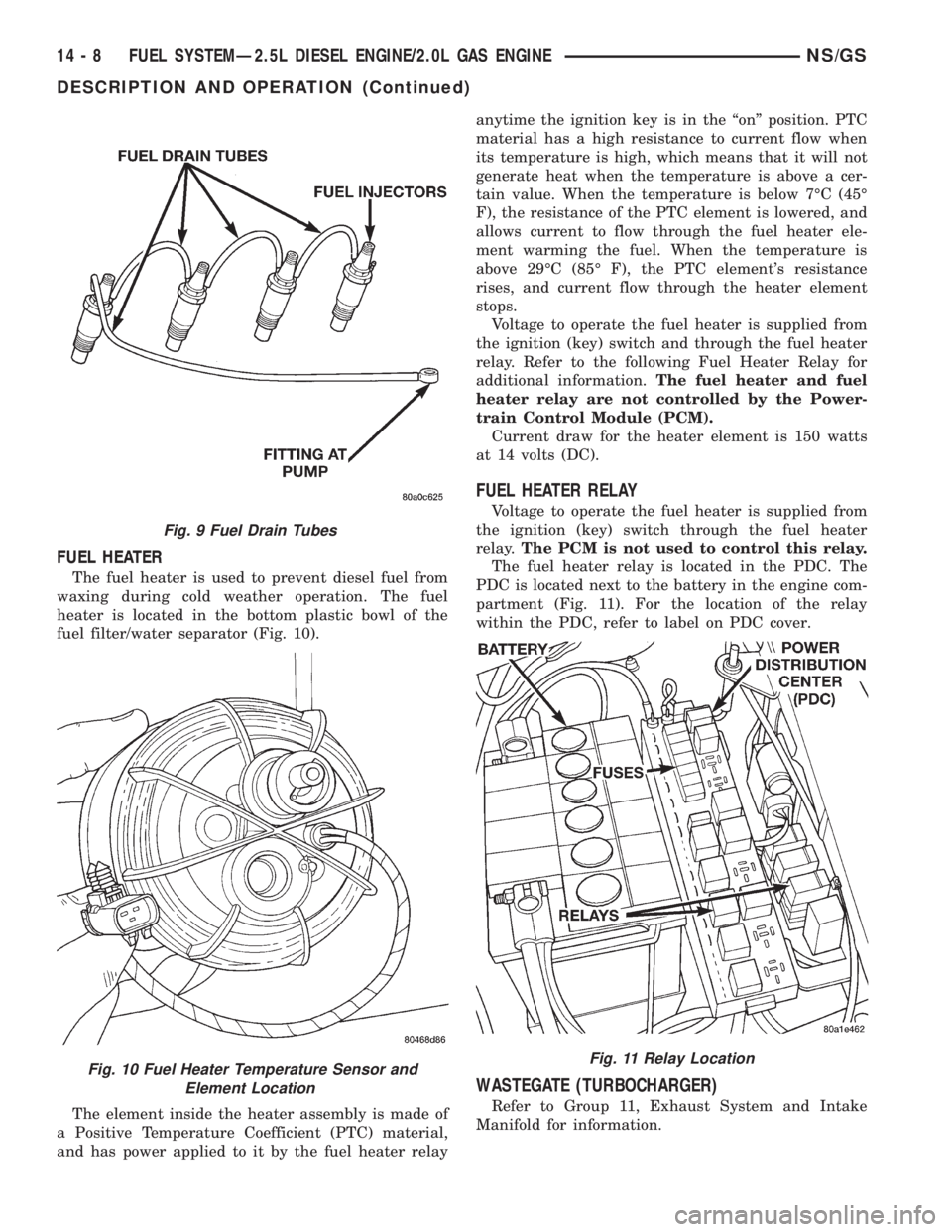
FUEL HEATER
The fuel heater is used to prevent diesel fuel from
waxing during cold weather operation. The fuel
heater is located in the bottom plastic bowl of the
fuel filter/water separator (Fig. 10).
The element inside the heater assembly is made of
a Positive Temperature Coefficient (PTC) material,
and has power applied to it by the fuel heater relayanytime the ignition key is in the ªonº position. PTC
material has a high resistance to current flow when
its temperature is high, which means that it will not
generate heat when the temperature is above a cer-
tain value. When the temperature is below 7ÉC (45É
F), the resistance of the PTC element is lowered, and
allows current to flow through the fuel heater ele-
ment warming the fuel. When the temperature is
above 29ÉC (85É F), the PTC element's resistance
rises, and current flow through the heater element
stops.
Voltage to operate the fuel heater is supplied from
the ignition (key) switch and through the fuel heater
relay. Refer to the following Fuel Heater Relay for
additional information.The fuel heater and fuel
heater relay are not controlled by the Power-
train Control Module (PCM).
Current draw for the heater element is 150 watts
at 14 volts (DC).
FUEL HEATER RELAY
Voltage to operate the fuel heater is supplied from
the ignition (key) switch through the fuel heater
relay.The PCM is not used to control this relay.
The fuel heater relay is located in the PDC. The
PDC is located next to the battery in the engine com-
partment (Fig. 11). For the location of the relay
within the PDC, refer to label on PDC cover.
WASTEGATE (TURBOCHARGER)
Refer to Group 11, Exhaust System and Intake
Manifold for information.
Fig. 9 Fuel Drain Tubes
Fig. 10 Fuel Heater Temperature Sensor and
Element LocationFig. 11 Relay Location
14 - 8 FUEL SYSTEMÐ2.5L DIESEL ENGINE/2.0L GAS ENGINENS/GS
DESCRIPTION AND OPERATION (Continued)
Page 1377 of 1938
DIAGNOSIS AND TESTING
GENERAL INFORMATION
This section of the group will cover a general diag-
nosis of diesel engine fuel system components.
Diagnostic Trouble Codes:Refer to On-Board
Diagnostics in Group 25, Emission Control System
for a list of Diagnostic Trouble Codes (DTC's) for cer-
tain fuel system components.
The PCM must be tested with the DRBIII scan
tool. The DRBIII should be the first step in any diag-
nosis of engine performance complaints. Refer to the
1997 GS 2.5L Diesel Powertrain Diagnostic Proce-
dures manual for diagnosis and testing of the diesel
engine control system.
VISUAL INSPECTION
A visual inspection for loose, disconnected, or incor-
rectly routed wires and hoses should be made before
attempting to diagnose or service the diesel fuel
injection system. A visual check will help find these
conditions. It also saves unnecessary test and diag-
nostic time. A thorough visual inspection of the fuel
injection system includes the following checks:
(1) Be sure that the battery connections are tight
and not corroded.
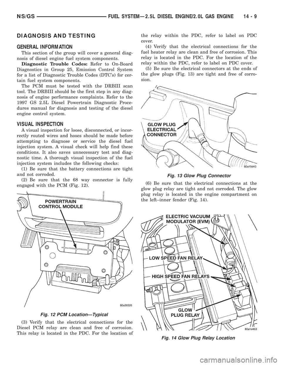
(2) Be sure that the 68 way connector is fully
engaged with the PCM (Fig. 12).
(3) Verify that the electrical connections for the
Diesel PCM relay are clean and free of corrosion.
This relay is located in the PDC. For the location ofthe relay within the PDC, refer to label on PDC
cover.
(4) Verify that the electrical connections for the
fuel heater relay are clean and free of corrosion. This
relay is located in the PDC. For the location of the
relay within the PDC, refer to label on PDC cover.
(5) Be sure the electrical connectors at the ends of
the glow plugs (Fig. 13) are tight and free of corro-
sion.
(6) Be sure that the electrical connections at the
glow plug relay are tight and not corroded. The glow
plug relay is located in the engine compartment on
the left±inner fender (Fig. 14).
Fig. 12 PCM LocationÐTypical
Fig. 13 Glow Plug Connector
Fig. 14 Glow Plug Relay Location
NS/GSFUEL SYSTEMÐ2.5L DIESEL ENGINE/2.0L GAS ENGINE 14 - 9
Page 1380 of 1938
FUEL HEATER RELAY TEST
The fuel heater relay is located in the Power Dis-
tribution Center (PDC). Refer to RelaysÐOperation/
Testing in Fuel Ingection System section of this
group for test procedures.
FUEL INJECTOR TEST
The fuel injection nozzels, located on the engine
cylinder head, spray fuel under high pressure into
the individual combustion chambers. Pressurized
fuel, delivered by the fuel injection pump, unseats a
spring-loaded needle valve inside the injector, and
the fuel is atomized as it escapes through the injector
opening into the engine's combustion chamber. If the
fuel injector does not operate properly, the engine
may misfire, or cause other driveability problems.
A leak in the injection pump±to±injector high±pres-
sure fuel line can cause many of the same symptoms
as a malfunctioning injector. Inspect for a leak in the
high±pressure lines before checking for a malfunc-
tioning fuel injector.
WARNING: THE INJECTION PUMP SUPPLIES HIGH-
±PRESSURE FUEL OF UP TO APPROXIMATELY
45,000 KPA (6526 PSI) TO EACH INDIVIDUAL INJEC-
TOR THROUGH THE HIGH±PRESSURE LINES. FUEL
UNDER THIS AMOUNT OF PRESSURE CAN PENE-
TRATE THE SKIN AND CAUSE PERSONAL INJURY.
WEAR SAFETY GOGGLES AND ADEQUATE PRO-
TECTIVE CLOTHING. AVOID CONTACT WITH FUEL
SPRAY WHEN BLEEDING HIGH±PRESSURE FUEL
LINES.
WARNING: DO NOT BLEED AIR FROM THE FUEL
SYSTEM OF A HOT ENGINE. DO NOT ALLOW FUEL
TO SPRAY ONTO THE EXHAUST MANIFOLD WHEN
BLEEDING AIR FROM THE FUEL SYSTEM.
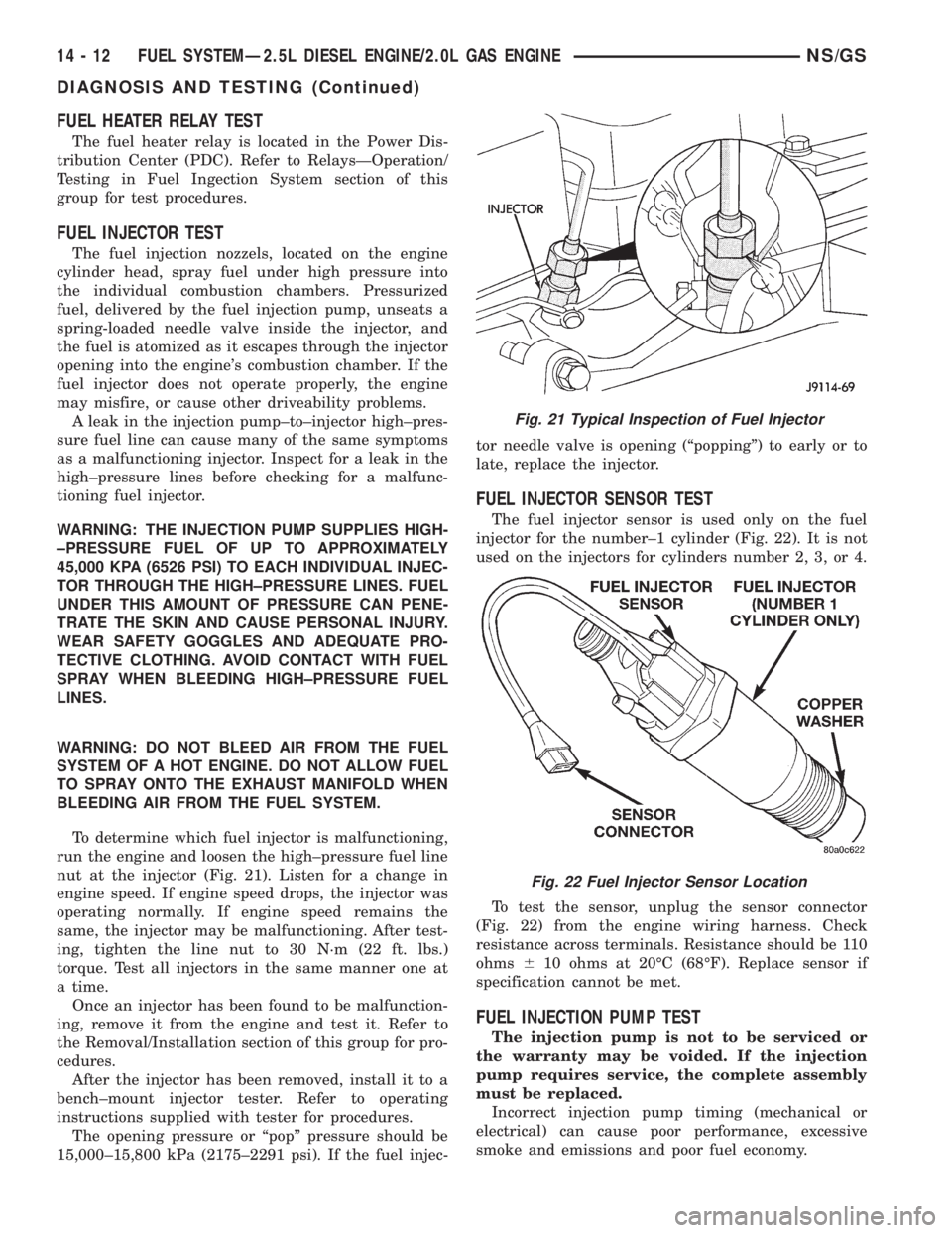
To determine which fuel injector is malfunctioning,
run the engine and loosen the high±pressure fuel line
nut at the injector (Fig. 21). Listen for a change in
engine speed. If engine speed drops, the injector was
operating normally. If engine speed remains the
same, the injector may be malfunctioning. After test-
ing, tighten the line nut to 30 N´m (22 ft. lbs.)
torque. Test all injectors in the same manner one at
a time.
Once an injector has been found to be malfunction-
ing, remove it from the engine and test it. Refer to
the Removal/Installation section of this group for pro-
cedures.
After the injector has been removed, install it to a
bench±mount injector tester. Refer to operating
instructions supplied with tester for procedures.
The opening pressure or ªpopº pressure should be
15,000±15,800 kPa (2175±2291 psi). If the fuel injec-tor needle valve is opening (ªpoppingº) to early or to
late, replace the injector.
FUEL INJECTOR SENSOR TEST
The fuel injector sensor is used only on the fuel
injector for the number±1 cylinder (Fig. 22). It is not
used on the injectors for cylinders number 2, 3, or 4.
To test the sensor, unplug the sensor connector
(Fig. 22) from the engine wiring harness. Check
resistance across terminals. Resistance should be 110
ohms610 ohms at 20ÉC (68ÉF). Replace sensor if
specification cannot be met.
FUEL INJECTION PUMP TEST
The injection pump is not to be serviced or
the warranty may be voided. If the injection
pump requires service, the complete assembly
must be replaced.
Incorrect injection pump timing (mechanical or
electrical) can cause poor performance, excessive
smoke and emissions and poor fuel economy.
Fig. 21 Typical Inspection of Fuel Injector
Fig. 22 Fuel Injector Sensor Location
14 - 12 FUEL SYSTEMÐ2.5L DIESEL ENGINE/2.0L GAS ENGINENS/GS
DIAGNOSIS AND TESTING (Continued)
Page 1385 of 1938
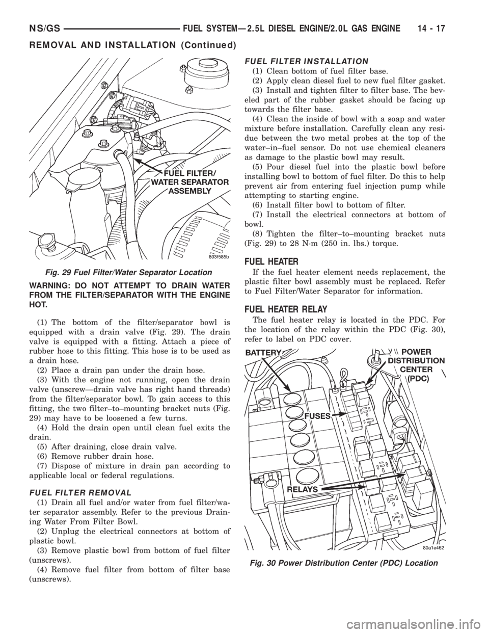
WARNING: DO NOT ATTEMPT TO DRAIN WATER
FROM THE FILTER/SEPARATOR WITH THE ENGINE
HOT.
(1) The bottom of the filter/separator bowl is
equipped with a drain valve (Fig. 29). The drain
valve is equipped with a fitting. Attach a piece of
rubber hose to this fitting. This hose is to be used as
a drain hose.
(2) Place a drain pan under the drain hose.
(3) With the engine not running, open the drain
valve (unscrewÐdrain valve has right hand threads)
from the filter/separator bowl. To gain access to this
fitting, the two filter±to±mounting bracket nuts (Fig.
29) may have to be loosened a few turns.
(4) Hold the drain open until clean fuel exits the
drain.
(5) After draining, close drain valve.
(6) Remove rubber drain hose.
(7) Dispose of mixture in drain pan according to
applicable local or federal regulations.
FUEL FILTER REMOVAL
(1) Drain all fuel and/or water from fuel filter/wa-
ter separator assembly. Refer to the previous Drain-
ing Water From Filter Bowl.
(2) Unplug the electrical connectors at bottom of
plastic bowl.
(3) Remove plastic bowl from bottom of fuel filter
(unscrews).
(4) Remove fuel filter from bottom of filter base
(unscrews).
FUEL FILTER INSTALLATION
(1) Clean bottom of fuel filter base.
(2) Apply clean diesel fuel to new fuel filter gasket.
(3) Install and tighten filter to filter base. The bev-
eled part of the rubber gasket should be facing up
towards the filter base.
(4) Clean the inside of bowl with a soap and water
mixture before installation. Carefully clean any resi-
due between the two metal probes at the top of the
water±in±fuel sensor. Do not use chemical cleaners
as damage to the plastic bowl may result.
(5) Pour diesel fuel into the plastic bowl before
installing bowl to bottom of fuel filter. Do this to help
prevent air from entering fuel injection pump while
attempting to starting engine.
(6) Install filter bowl to bottom of filter.
(7) Install the electrical connectors at bottom of
bowl.
(8) Tighten the filter±to±mounting bracket nuts
(Fig. 29) to 28 N´m (250 in. lbs.) torque.
FUEL HEATER
If the fuel heater element needs replacement, the
plastic filter bowl assembly must be replaced. Refer
to Fuel Filter/Water Separator for information.
FUEL HEATER RELAY
The fuel heater relay is located in the PDC. For
the location of the relay within the PDC (Fig. 30),
refer to label on PDC cover.
Fig. 29 Fuel Filter/Water Separator Location
Fig. 30 Power Distribution Center (PDC) Location
NS/GSFUEL SYSTEMÐ2.5L DIESEL ENGINE/2.0L GAS ENGINE 14 - 17
REMOVAL AND INSTALLATION (Continued)
Page 1400 of 1938
FUEL INJECTION SYSTEMÐ2.0L ENGINE
INDEX
page page
GENERAL INFORMATION
INTRODUCTIONÐ2.0L ENGINE............ 32
MODES OF OPERATIONÐ2.0L ENGINE..... 32
DESCRIPTION AND OPERATION
AIR CONDITIONING (A/C) RELAYÐPCM
OUTPUTÐ2.0L ENGINE................ 35
AIR CONDITIONING PRESSURE
TRANSDUCERÐPCM INPUTÐ
2.0L ENGINE......................... 33
AIR CONDITIONING SWITCH SENSEÐ
PCM INPUTÐ2.0L ENGINE.............. 33
AUTOMATIC SHUTDOWN (ASD) SENSEÐ
PCM INPUTÐ2.0L ENGINE.............. 33
AUTOMATIC SHUTDOWN RELAYÐ
PCM OUTPUTÐ2.0L ENGINE............ 35
BATTERY VOLTAGEÐPCM INPUTÐ
2.0L ENGINE......................... 33
CAMSHAFT POSITION SENSORÐ
PCM INPUTÐ2.0L ENGINE.............. 33
CRANKSHAFT POSITION SENSORÐ
PCM INPUTÐ2.0L ENGINE.............. 33
DATA LINK CONNECTORÐPCM OUTPUTÐ
2.0L ENGINE......................... 35
ELECTRONIC EGR TRANSDUCERÐ
PCM OUTPUTÐ2.0L ENGINE............ 35
ENGINE COOLANT TEMPERATURE SENSORÐ
PCM INPUTÐ2.0L ENGINE.............. 33
FUEL INJECTORSÐPCM OUTPUTÐ
2.0L ENGINE......................... 35
FUEL PUMP RELAYÐPCM OUTPUTÐ
2.0L ENGINE......................... 35
GENERATOR FIELDÐPCM OUTPUTÐ
2.0L ENGINE......................... 35
HEATED OXYGEN SENSORÐPCM INPUTÐ
2.0L ENGINE......................... 33
IDLE AIR CONTROL MOTORÐPCM OUTPUTÐ
2.0L ENGINE......................... 35
IGNITION COILÐPCM OUTPUTÐ
2.0L ENGINE......................... 36KNOCK SENSORÐPCM INPUTÐ
2.0L ENGINE......................... 34
MALFUNCTION INDICATOR (CHECK ENGINE)
LAMPÐPCM OUTPUTÐ2.0L ENGINE...... 36
MANIFOLD ABSOLUTE PRESSURE
(MAP SENSOR)ÐPCM INPUTÐ
2.0L ENGINE......................... 34
POWERTRAIN CONTROL MODULEÐ
2.0L ENGINE......................... 33
RADIATOR FAN CONTROL MODULEÐ
PCM OUTPUTÐ2.0L ENGINE............ 36
SPEED CONTROL SOLENOIDSÐ
PCM OUTPUTÐ2.0L ENGINE............ 36
SPEED CONTROLÐPCM INPUTÐ
2.0L ENGINE......................... 34
STARTER RELAYÐPCM OUTPUTÐ
2.0L ENGINE......................... 35
SYSTEM DIAGNOSISÐ2.0L ENGINE........ 33
TACHOMETERÐPCM OUTPUTÐ
2.0L ENGINE......................... 36
THROTTLE BODYÐ2.0L ENGINE.......... 36
THROTTLE POSITION SENSOR/ IDLE AIR
CONTROL MOTORÐPCM INPUTÐ
2.0L ENGINE......................... 35
DIAGNOSIS AND TESTING
ASD AND FUEL PUMP RELAYSÐ
2.0L ENGINE......................... 39
CAMSHAFT AND CRANKSHAFT
POSITION SENSOR................... 40
ENGINE COOLANT TEMPERATURE
SENSOR............................ 40
KNOCK SENSORÐ2.0L ENGINE........... 40
MANIFOLD ABSOLUTE PRESSURE
(MAP) SENSORÐ2.0L ENGINE........... 39
THROTTLE BODY MINIMUM AIR FLOW..... 41
THROTTLE POSITION SENSOR........... 40
VISUAL INSPECTIONÐSOHC............. 36
SPECIFICATIONS
TORQUE............................. 42
GENERAL INFORMATION
INTRODUCTIONÐ2.0L ENGINE
Refer to the Introduction for 2.4/3.0/3.3/3.8L
engines under General Information in the Fuel Injec-
tion System section of group 14 for more information.
MODES OF OPERATIONÐ2.0L ENGINE
Refer to the Modes of Operation for 2.4/3.0/3.3/3.8L
engines under General Information in the Fuel Injec-
tion System section of group 14 for more information.
14 - 32 FUEL SYSTEMÐ2.5L DIESEL ENGINE/2.0L GAS ENGINENS/GS
Page 1403 of 1938
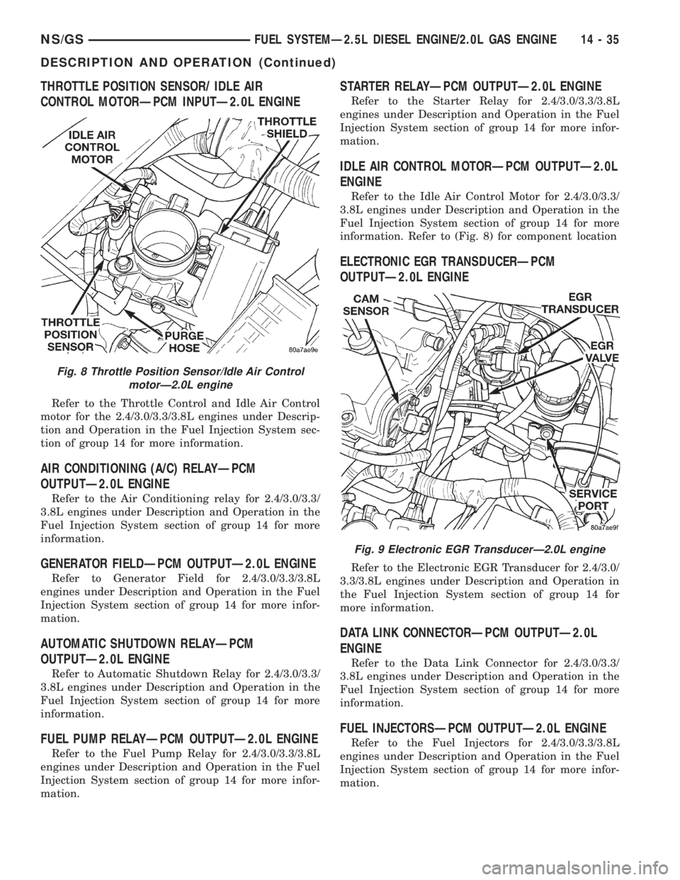
THROTTLE POSITION SENSOR/ IDLE AIR
CONTROL MOTORÐPCM INPUTÐ2.0L ENGINE
Refer to the Throttle Control and Idle Air Control
motor for the 2.4/3.0/3.3/3.8L engines under Descrip-
tion and Operation in the Fuel Injection System sec-
tion of group 14 for more information.
AIR CONDITIONING (A/C) RELAYÐPCM
OUTPUTÐ2.0L ENGINE
Refer to the Air Conditioning relay for 2.4/3.0/3.3/
3.8L engines under Description and Operation in the
Fuel Injection System section of group 14 for more
information.
GENERATOR FIELDÐPCM OUTPUTÐ2.0L ENGINE
Refer to Generator Field for 2.4/3.0/3.3/3.8L
engines under Description and Operation in the Fuel
Injection System section of group 14 for more infor-
mation.
AUTOMATIC SHUTDOWN RELAYÐPCM
OUTPUTÐ2.0L ENGINE
Refer to Automatic Shutdown Relay for 2.4/3.0/3.3/
3.8L engines under Description and Operation in the
Fuel Injection System section of group 14 for more
information.
FUEL PUMP RELAYÐPCM OUTPUTÐ2.0L ENGINE
Refer to the Fuel Pump Relay for 2.4/3.0/3.3/3.8L
engines under Description and Operation in the Fuel
Injection System section of group 14 for more infor-
mation.
STARTER RELAYÐPCM OUTPUTÐ2.0L ENGINE
Refer to the Starter Relay for 2.4/3.0/3.3/3.8L
engines under Description and Operation in the Fuel
Injection System section of group 14 for more infor-
mation.
IDLE AIR CONTROL MOTORÐPCM OUTPUTÐ2.0L
ENGINE
Refer to the Idle Air Control Motor for 2.4/3.0/3.3/
3.8L engines under Description and Operation in the
Fuel Injection System section of group 14 for more
information. Refer to (Fig. 8) for component location
ELECTRONIC EGR TRANSDUCERÐPCM
OUTPUTÐ2.0L ENGINE
Refer to the Electronic EGR Transducer for 2.4/3.0/
3.3/3.8L engines under Description and Operation in
the Fuel Injection System section of group 14 for
more information.
DATA LINK CONNECTORÐPCM OUTPUTÐ2.0L
ENGINE
Refer to the Data Link Connector for 2.4/3.0/3.3/
3.8L engines under Description and Operation in the
Fuel Injection System section of group 14 for more
information.
FUEL INJECTORSÐPCM OUTPUTÐ2.0L ENGINE
Refer to the Fuel Injectors for 2.4/3.0/3.3/3.8L
engines under Description and Operation in the Fuel
Injection System section of group 14 for more infor-
mation.
Fig. 8 Throttle Position Sensor/Idle Air Control
motorÐ2.0L engine
Fig. 9 Electronic EGR TransducerÐ2.0L engine
NS/GSFUEL SYSTEMÐ2.5L DIESEL ENGINE/2.0L GAS ENGINE 14 - 35
DESCRIPTION AND OPERATION (Continued)
Page 1404 of 1938
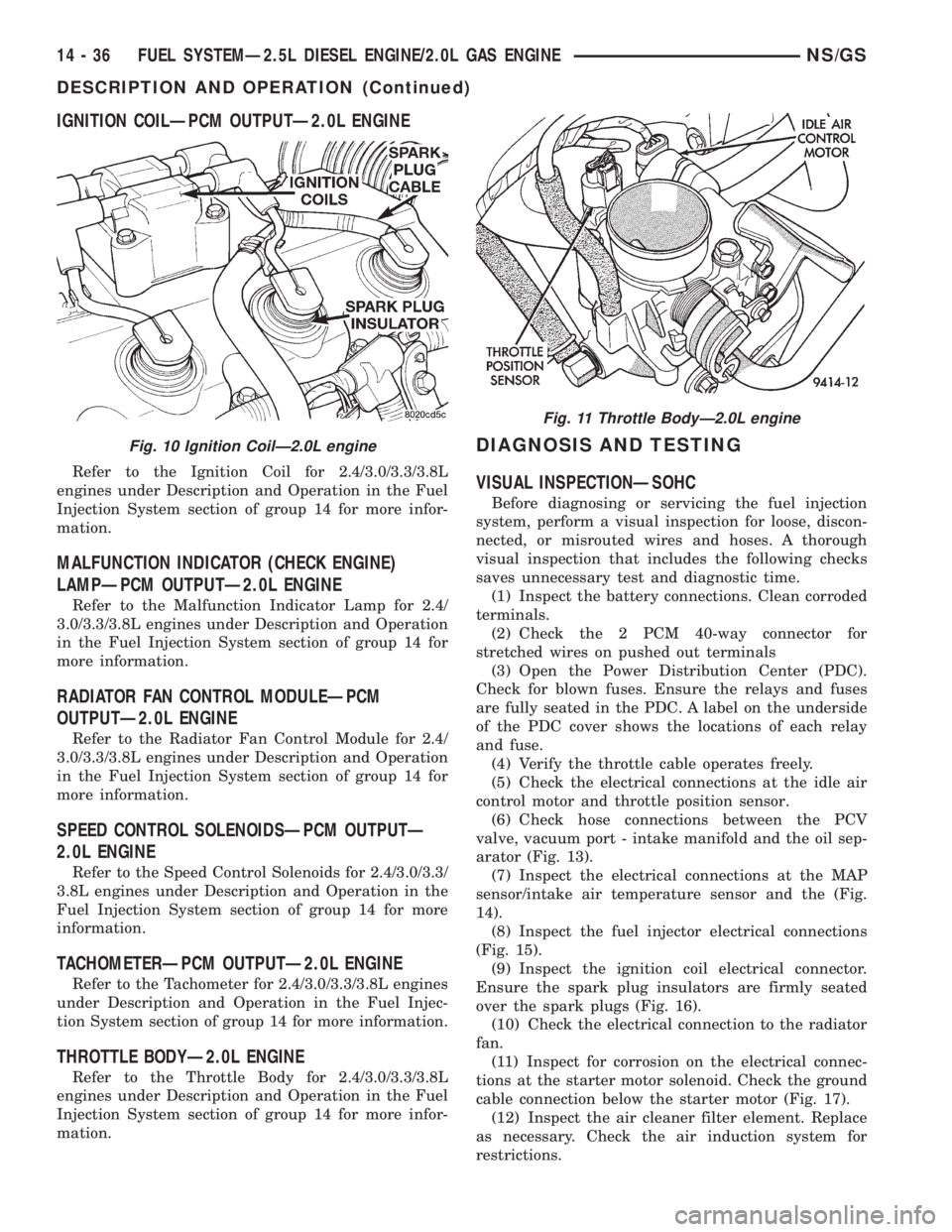
IGNITION COILÐPCM OUTPUTÐ2.0L ENGINE
Refer to the Ignition Coil for 2.4/3.0/3.3/3.8L
engines under Description and Operation in the Fuel
Injection System section of group 14 for more infor-
mation.
MALFUNCTION INDICATOR (CHECK ENGINE)
LAMPÐPCM OUTPUTÐ2.0L ENGINE
Refer to the Malfunction Indicator Lamp for 2.4/
3.0/3.3/3.8L engines under Description and Operation
in the Fuel Injection System section of group 14 for
more information.
RADIATOR FAN CONTROL MODULEÐPCM
OUTPUTÐ2.0L ENGINE
Refer to the Radiator Fan Control Module for 2.4/
3.0/3.3/3.8L engines under Description and Operation
in the Fuel Injection System section of group 14 for
more information.
SPEED CONTROL SOLENOIDSÐPCM OUTPUTÐ
2.0L ENGINE
Refer to the Speed Control Solenoids for 2.4/3.0/3.3/
3.8L engines under Description and Operation in the
Fuel Injection System section of group 14 for more
information.
TACHOMETERÐPCM OUTPUTÐ2.0L ENGINE
Refer to the Tachometer for 2.4/3.0/3.3/3.8L engines
under Description and Operation in the Fuel Injec-
tion System section of group 14 for more information.
THROTTLE BODYÐ2.0L ENGINE
Refer to the Throttle Body for 2.4/3.0/3.3/3.8L
engines under Description and Operation in the Fuel
Injection System section of group 14 for more infor-
mation.
DIAGNOSIS AND TESTING
VISUAL INSPECTIONÐSOHC
Before diagnosing or servicing the fuel injection
system, perform a visual inspection for loose, discon-
nected, or misrouted wires and hoses. A thorough
visual inspection that includes the following checks
saves unnecessary test and diagnostic time.
(1) Inspect the battery connections. Clean corroded
terminals.
(2) Check the 2 PCM 40-way connector for
stretched wires on pushed out terminals
(3) Open the Power Distribution Center (PDC).
Check for blown fuses. Ensure the relays and fuses
are fully seated in the PDC. A label on the underside
of the PDC cover shows the locations of each relay
and fuse.
(4) Verify the throttle cable operates freely.
(5) Check the electrical connections at the idle air
control motor and throttle position sensor.
(6) Check hose connections between the PCV
valve, vacuum port - intake manifold and the oil sep-
arator (Fig. 13).
(7) Inspect the electrical connections at the MAP
sensor/intake air temperature sensor and the (Fig.
14).
(8) Inspect the fuel injector electrical connections
(Fig. 15).
(9) Inspect the ignition coil electrical connector.
Ensure the spark plug insulators are firmly seated
over the spark plugs (Fig. 16).
(10) Check the electrical connection to the radiator
fan.
(11) Inspect for corrosion on the electrical connec-
tions at the starter motor solenoid. Check the ground
cable connection below the starter motor (Fig. 17).
(12) Inspect the air cleaner filter element. Replace
as necessary. Check the air induction system for
restrictions.
Fig. 10 Ignition CoilÐ2.0L engine
Fig. 11 Throttle BodyÐ2.0L engine
14 - 36 FUEL SYSTEMÐ2.5L DIESEL ENGINE/2.0L GAS ENGINENS/GS
DESCRIPTION AND OPERATION (Continued)
Page 1407 of 1938
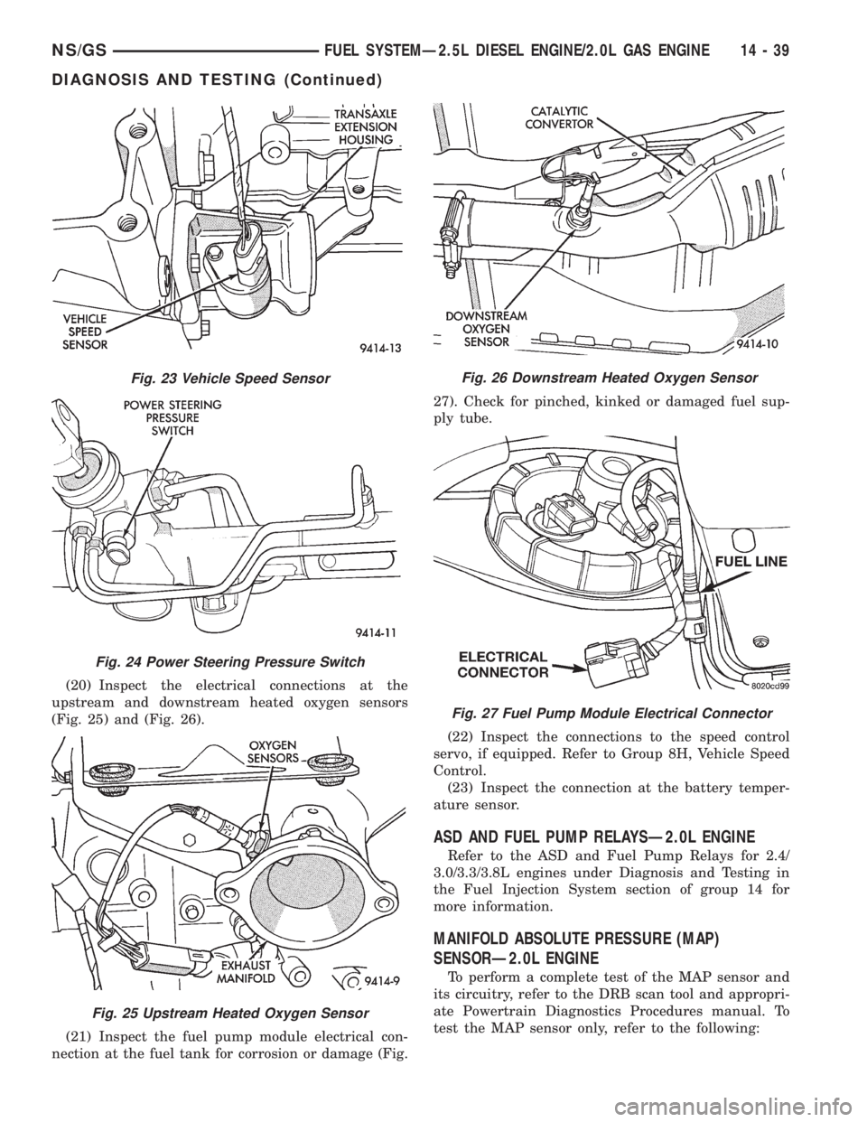
(20) Inspect the electrical connections at the
upstream and downstream heated oxygen sensors
(Fig. 25) and (Fig. 26).
(21) Inspect the fuel pump module electrical con-
nection at the fuel tank for corrosion or damage (Fig.27). Check for pinched, kinked or damaged fuel sup-
ply tube.
(22) Inspect the connections to the speed control
servo, if equipped. Refer to Group 8H, Vehicle Speed
Control.
(23) Inspect the connection at the battery temper-
ature sensor.
ASD AND FUEL PUMP RELAYSÐ2.0L ENGINE
Refer to the ASD and Fuel Pump Relays for 2.4/
3.0/3.3/3.8L engines under Diagnosis and Testing in
the Fuel Injection System section of group 14 for
more information.
MANIFOLD ABSOLUTE PRESSURE (MAP)
SENSORÐ2.0L ENGINE
To perform a complete test of the MAP sensor and
its circuitry, refer to the DRB scan tool and appropri-
ate Powertrain Diagnostics Procedures manual. To
test the MAP sensor only, refer to the following:
Fig. 23 Vehicle Speed Sensor
Fig. 24 Power Steering Pressure Switch
Fig. 25 Upstream Heated Oxygen Sensor
Fig. 26 Downstream Heated Oxygen Sensor
Fig. 27 Fuel Pump Module Electrical Connector
NS/GSFUEL SYSTEMÐ2.5L DIESEL ENGINE/2.0L GAS ENGINE 14 - 39
DIAGNOSIS AND TESTING (Continued)
Page 1408 of 1938
CAUTION: When testing the MAP sensor, be sure
that the harness wires are not damaged by the test
meter probes.
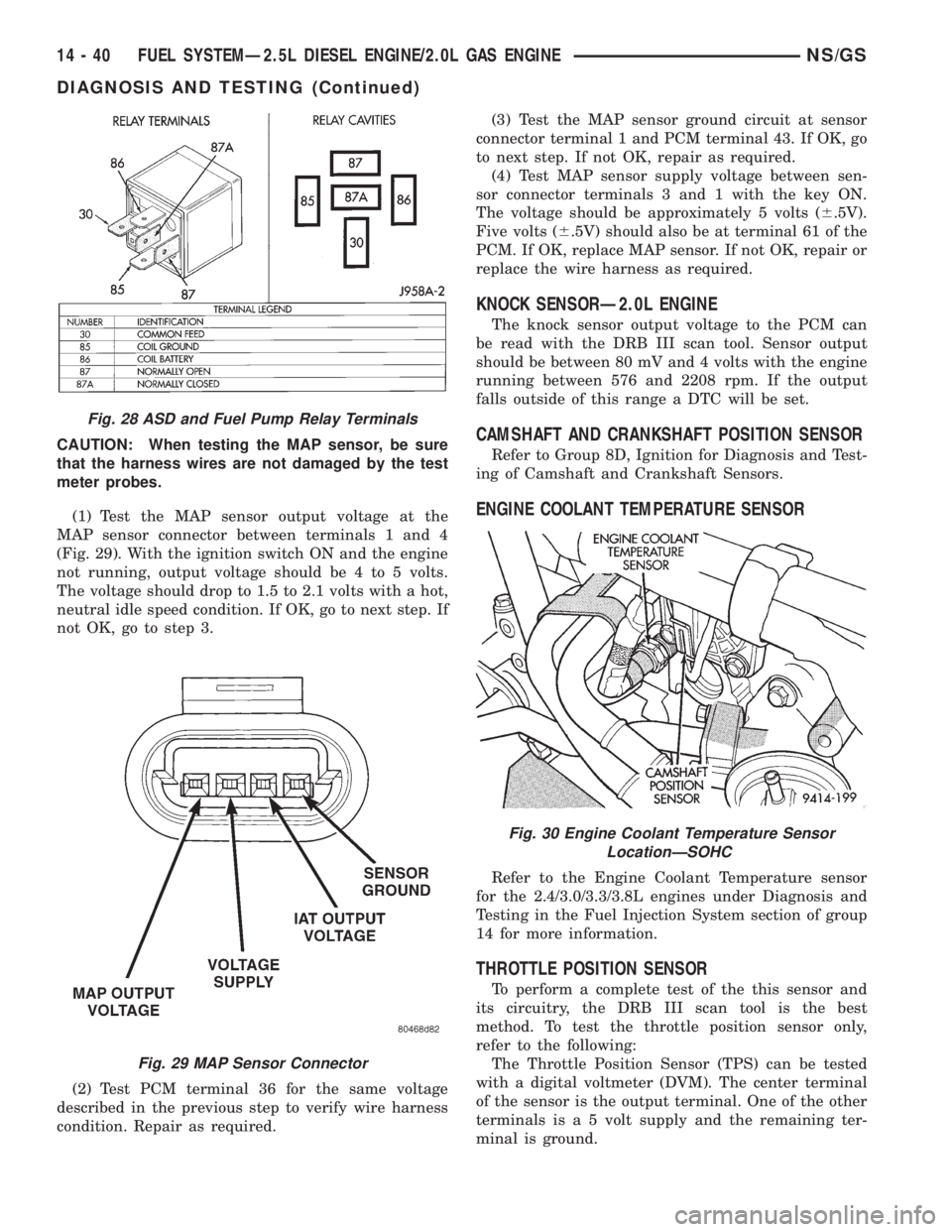
(1) Test the MAP sensor output voltage at the
MAP sensor connector between terminals 1 and 4
(Fig. 29). With the ignition switch ON and the engine
not running, output voltage should be 4 to 5 volts.
The voltage should drop to 1.5 to 2.1 volts with a hot,
neutral idle speed condition. If OK, go to next step. If
not OK, go to step 3.
(2) Test PCM terminal 36 for the same voltage
described in the previous step to verify wire harness
condition. Repair as required.(3) Test the MAP sensor ground circuit at sensor
connector terminal 1 and PCM terminal 43. If OK, go
to next step. If not OK, repair as required.
(4) Test MAP sensor supply voltage between sen-
sor connector terminals 3 and 1 with the key ON.
The voltage should be approximately 5 volts (6.5V).
Five volts (6.5V) should also be at terminal 61 of the
PCM. If OK, replace MAP sensor. If not OK, repair or
replace the wire harness as required.
KNOCK SENSORÐ2.0L ENGINE
The knock sensor output voltage to the PCM can
be read with the DRB III scan tool. Sensor output
should be between 80 mV and 4 volts with the engine
running between 576 and 2208 rpm. If the output
falls outside of this range a DTC will be set.
CAMSHAFT AND CRANKSHAFT POSITION SENSOR
Refer to Group 8D, Ignition for Diagnosis and Test-
ing of Camshaft and Crankshaft Sensors.
ENGINE COOLANT TEMPERATURE SENSOR
Refer to the Engine Coolant Temperature sensor
for the 2.4/3.0/3.3/3.8L engines under Diagnosis and
Testing in the Fuel Injection System section of group
14 for more information.
THROTTLE POSITION SENSOR
To perform a complete test of the this sensor and
its circuitry, the DRB III scan tool is the best
method. To test the throttle position sensor only,
refer to the following:
The Throttle Position Sensor (TPS) can be tested
with a digital voltmeter (DVM). The center terminal
of the sensor is the output terminal. One of the other
terminals is a 5 volt supply and the remaining ter-
minal is ground.
Fig. 28 ASD and Fuel Pump Relay Terminals
Fig. 29 MAP Sensor Connector
Fig. 30 Engine Coolant Temperature Sensor
LocationÐSOHC
14 - 40 FUEL SYSTEMÐ2.5L DIESEL ENGINE/2.0L GAS ENGINENS/GS
DIAGNOSIS AND TESTING (Continued)