relay CHRYSLER VOYAGER 1996 Service Manual
[x] Cancel search | Manufacturer: CHRYSLER, Model Year: 1996, Model line: VOYAGER, Model: CHRYSLER VOYAGER 1996Pages: 1938, PDF Size: 55.84 MB
Page 1336 of 1938
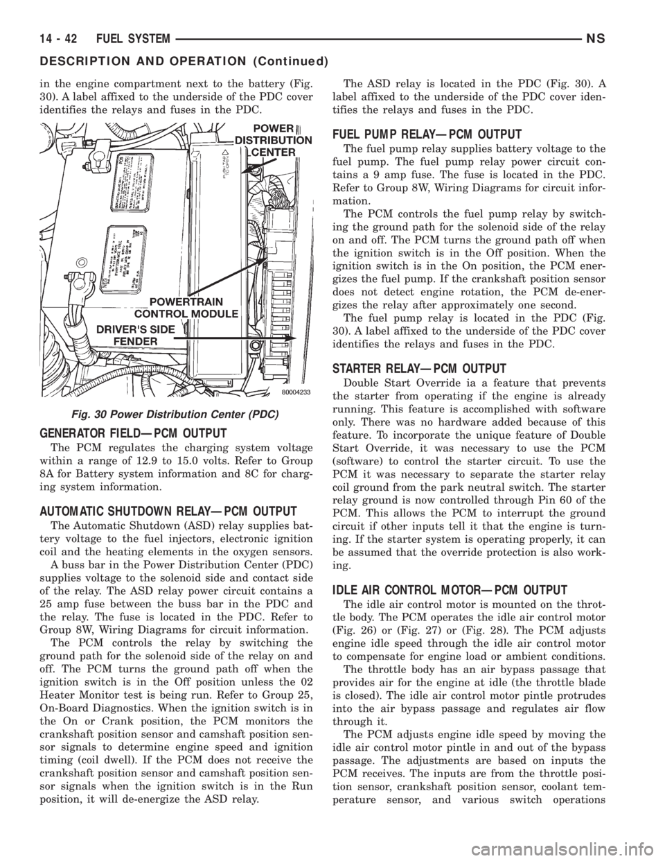
in the engine compartment next to the battery (Fig.
30). A label affixed to the underside of the PDC cover
identifies the relays and fuses in the PDC.
GENERATOR FIELDÐPCM OUTPUT
The PCM regulates the charging system voltage
within a range of 12.9 to 15.0 volts. Refer to Group
8A for Battery system information and 8C for charg-
ing system information.
AUTOMATIC SHUTDOWN RELAYÐPCM OUTPUT
The Automatic Shutdown (ASD) relay supplies bat-
tery voltage to the fuel injectors, electronic ignition
coil and the heating elements in the oxygen sensors.
A buss bar in the Power Distribution Center (PDC)
supplies voltage to the solenoid side and contact side
of the relay. The ASD relay power circuit contains a
25 amp fuse between the buss bar in the PDC and
the relay. The fuse is located in the PDC. Refer to
Group 8W, Wiring Diagrams for circuit information.
The PCM controls the relay by switching the
ground path for the solenoid side of the relay on and
off. The PCM turns the ground path off when the
ignition switch is in the Off position unless the 02
Heater Monitor test is being run. Refer to Group 25,
On-Board Diagnostics. When the ignition switch is in
the On or Crank position, the PCM monitors the
crankshaft position sensor and camshaft position sen-
sor signals to determine engine speed and ignition
timing (coil dwell). If the PCM does not receive the
crankshaft position sensor and camshaft position sen-
sor signals when the ignition switch is in the Run
position, it will de-energize the ASD relay.The ASD relay is located in the PDC (Fig. 30). A
label affixed to the underside of the PDC cover iden-
tifies the relays and fuses in the PDC.
FUEL PUMP RELAYÐPCM OUTPUT
The fuel pump relay supplies battery voltage to the
fuel pump. The fuel pump relay power circuit con-
tains a 9 amp fuse. The fuse is located in the PDC.
Refer to Group 8W, Wiring Diagrams for circuit infor-
mation.
The PCM controls the fuel pump relay by switch-
ing the ground path for the solenoid side of the relay
on and off. The PCM turns the ground path off when
the ignition switch is in the Off position. When the
ignition switch is in the On position, the PCM ener-
gizes the fuel pump. If the crankshaft position sensor
does not detect engine rotation, the PCM de-ener-
gizes the relay after approximately one second.
The fuel pump relay is located in the PDC (Fig.
30). A label affixed to the underside of the PDC cover
identifies the relays and fuses in the PDC.
STARTER RELAYÐPCM OUTPUT
Double Start Override ia a feature that prevents
the starter from operating if the engine is already
running. This feature is accomplished with software
only. There was no hardware added because of this
feature. To incorporate the unique feature of Double
Start Override, it was necessary to use the PCM
(software) to control the starter circuit. To use the
PCM it was necessary to separate the starter relay
coil ground from the park neutral switch. The starter
relay ground is now controlled through Pin 60 of the
PCM. This allows the PCM to interrupt the ground
circuit if other inputs tell it that the engine is turn-
ing. If the starter system is operating properly, it can
be assumed that the override protection is also work-
ing.
IDLE AIR CONTROL MOTORÐPCM OUTPUT
The idle air control motor is mounted on the throt-
tle body. The PCM operates the idle air control motor
(Fig. 26) or (Fig. 27) or (Fig. 28). The PCM adjusts
engine idle speed through the idle air control motor
to compensate for engine load or ambient conditions.
The throttle body has an air bypass passage that
provides air for the engine at idle (the throttle blade
is closed). The idle air control motor pintle protrudes
into the air bypass passage and regulates air flow
through it.
The PCM adjusts engine idle speed by moving the
idle air control motor pintle in and out of the bypass
passage. The adjustments are based on inputs the
PCM receives. The inputs are from the throttle posi-
tion sensor, crankshaft position sensor, coolant tem-
perature sensor, and various switch operations
Fig. 30 Power Distribution Center (PDC)
14 - 42 FUEL SYSTEMNS
DESCRIPTION AND OPERATION (Continued)
Page 1339 of 1938
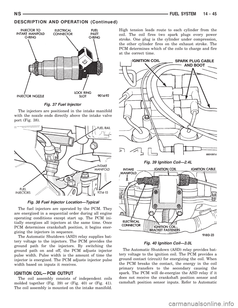
The injectors are positioned in the intake manifold
with the nozzle ends directly above the intake valve
port (Fig. 38).
The fuel injectors are operated by the PCM. They
are energized in a sequential order during all engine
operating conditions except start up. The PCM ini-
tially energizes all injectors at the same time. Once
PCM determines crankshaft position, it begins ener-
gizing the injectors in sequence.
The Automatic Shutdown (ASD) relay supplies bat-
tery voltage to the injectors. The PCM provides the
ground path for the injectors. By switching the
ground path on and off, the PCM adjusts injector
pulse width. Pulse width is the amount of time the
injector is energized. The PCM adjusts injector pulse
width based on inputs it receives.
IGNITION COILÐPCM OUTPUT
The coil assembly consists of independent coils
molded together (Fig. 39) or (Fig. 40) or (Fig. 41).
The coil assembly is mounted on the intake manifold.High tension leads route to each cylinder from the
coil. The coil fires two spark plugs every power
stroke. One plug is the cylinder under compression,
the other cylinder fires on the exhaust stroke. The
PCM determines which of the coils to charge and fire
at the correct time.
The Automatic Shutdown (ASD) relay provides bat-
tery voltage to the ignition coil. The PCM provides a
ground contact (circuit) for energizing the coil. When
the PCM breaks the contact, the energy in the coil
primary transfers to the secondary causing the
spark. The PCM will de-energize the ASD relay if it
does not receive the crankshaft position sensor and
camshaft position sensor inputs. Refer to Automatic
Fig. 37 Fuel Injector
Fig. 38 Fuel Injector LocationÐTypical
Fig. 39 Ignition CoilÐ2.4L
Fig. 40 Ignition CoilÐ3.0L
NSFUEL SYSTEM 14 - 45
DESCRIPTION AND OPERATION (Continued)
Page 1340 of 1938
Shutdown (ASD) RelayÐPCM Output in this section
for relay operation.
TORQUE CONVERTER CLUTCH SOLENOIDÐPCM
OUTPUT
Three-speed automatic transaxles use a torque con-
verter clutch solenoid. The PCM controls the engage-
ment of the torque converter clutch through the
solenoid. The torque converter clutch is engaged only
in direct drive mode. Refer to Group 21 for transaxle
information.
MALFUNCTION INDICATOR (CHECK ENGINE)
LAMPÐPCM OUTPUT
The PCM supplies the malfunction indicator (check
engine) lamp on/off signal to the instrument panel
through the CCD Bus. The CCD Bus is a communi-
cations port. Various modules use the CCD Bus to
exchange information.
The Check Engine lamp comes on each time the
ignition key is turned ON and stays on for 3 seconds
as a bulb test.
The Malfunction Indicator Lamp (MIL) stays on
continuously, when the PCM has entered a Limp-In
mode or identified a failed emission component. Dur-
ing Limp-in Mode, the PCM attempts to keep the
system operational. The MIL signals the need for
immediate service. In limp-in mode, the PCM com-
pensates for the failure of certain components that
send incorrect signals. The PCM substitutes for the
incorrect signals with inputs from other sensors.
If the PCM detects active engine misfire severe
enough to cause catalyst damage, it flashes the MIL.
At the same time the PCM also sets a Diagnostic
Trouble Code (DTC).
For signals that can trigger the MIL (Check
Engine Lamp) refer to Group 25, On-Board
Dianostics.
SOLID STATE FAN RELAYÐPCM OUTPUT
The radiator fan runs at a variable speed depend-
ing on coolant temperature and A/C system pressure.
The radiator fan circuit contains a Solid State Fan
Relay (SSFR). Refer to the Group 8W for a circuit
schematic.
A 5 volt signal is supplied to the SSFR. The PCM
provides a pulsed ground for the SSFR. Depending
upon the amount of pulse on time, the SSFR puts out
a proportional voltage to the fan motor at the lower
speed. For instance, if the on time is 30 percent, then
the voltage to the fan motor will be 3.6 volts.
When engine coolant reaches approximately 102ÉC
(215ÉF) the PCM grounds the SSFR relay. If engine
coolant reaches 207ÉC (225ÉF) the PCM grounds the
high speed ground relay and high speed fan relay. If
the fan operates at high speed, the PCM de-energizes
the high speed relay and high speed ground relay
when coolant temperature drops to approximately
101ÉC (214ÉF). When coolant temperature drops to
101ÉC (214ÉF) the fan operates at low speed. The
PCM de-energizes the low speed relay when coolant
temperature drops to approximately 93ÉC (199ÉF).
Also, when the air conditioning pressure switch
closes, the fan operates at high speed. The air condi-
tioning switch closes at 285 psi610 psi. When air
conditioning pressure drops approximately 40 psi, the
pressure switch opens and the fan operates at low
speed.
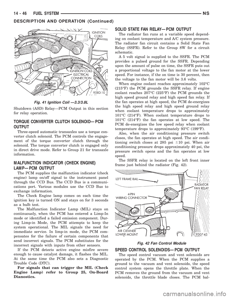
The SSFR relay is located on the left front inner
frame just behind the radiator (Fig. 42).
SPEED CONTROL SOLENOIDSÐPCM OUTPUT
The speed control vacuum and vent solenoids are
operated by the PCM. When the PCM supplies a
ground to the vacuum and vent solenoids, the speed
control system opens the throttle plate. When the
PCM removes the ground from the vacuum and vent
solenoids, the throttle blade closes. The PCM bal-
Fig. 41 Ignition Coil Ð3.3/3.8L
Fig. 42 Fan Control Module
14 - 46 FUEL SYSTEMNS
DESCRIPTION AND OPERATION (Continued)
Page 1345 of 1938
(22) Check the accessory drive belt tension.
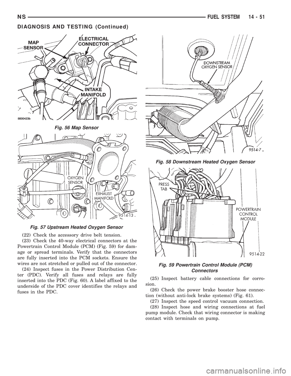
(23) Check the 40-way electrical connectors at the
Powertrain Control Module (PCM) (Fig. 59) for dam-
age or spread terminals. Verify that the connectors
are fully inserted into the PCM sockets. Ensure the
wires are not stretched or pulled out of the connector.
(24) Inspect fuses in the Power Distribution Cen-
ter (PDC). Verify all fuses and relays are fully
inserted into the PDC (Fig. 60). A label affixed to the
underside of the PDC cover identifies the relays and
fuses in the PDC.(25) Inspect battery cable connections for corro-
sion.
(26) Check the power brake booster hose connec-
tion (without anti-lock brake systems) (Fig. 61).
(27) Inspect the speed control vacuum connection.
(28) Inspect hose and wiring connections at fuel
pump module. Check that wiring connector is making
contact with terminals on pump.
Fig. 56 Map Sensor
Fig. 57 Upstream Heated Oxygen Sensor
Fig. 58 Downstream Heated Oxygen Sensor
Fig. 59 Powertrain Control Module (PCM)
Connectors
NSFUEL SYSTEM 14 - 51
DIAGNOSIS AND TESTING (Continued)
Page 1349 of 1938
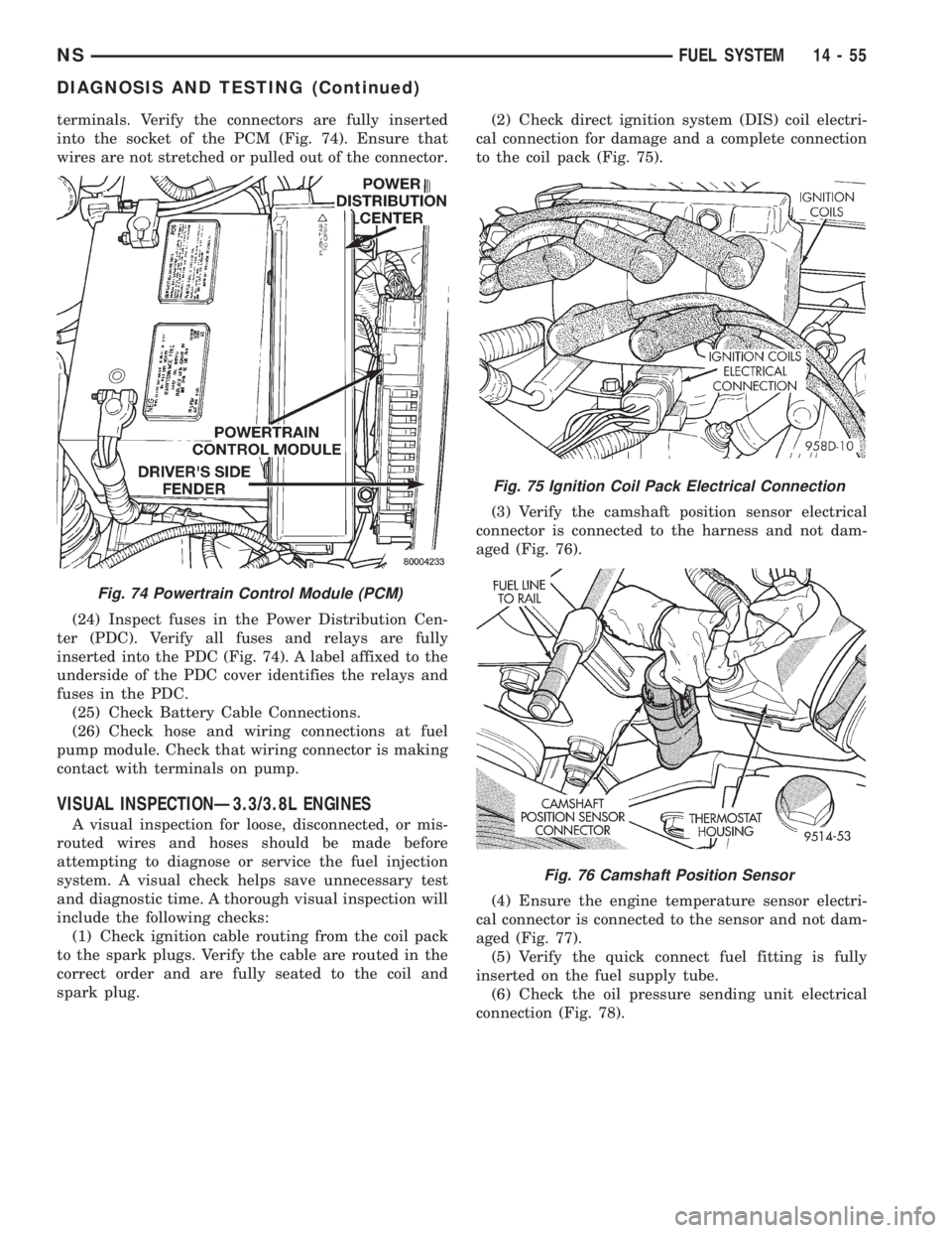
terminals. Verify the connectors are fully inserted
into the socket of the PCM (Fig. 74). Ensure that
wires are not stretched or pulled out of the connector.
(24) Inspect fuses in the Power Distribution Cen-
ter (PDC). Verify all fuses and relays are fully
inserted into the PDC (Fig. 74). A label affixed to the
underside of the PDC cover identifies the relays and
fuses in the PDC.
(25) Check Battery Cable Connections.
(26) Check hose and wiring connections at fuel
pump module. Check that wiring connector is making
contact with terminals on pump.
VISUAL INSPECTIONÐ3.3/3.8L ENGINES
A visual inspection for loose, disconnected, or mis-
routed wires and hoses should be made before
attempting to diagnose or service the fuel injection
system. A visual check helps save unnecessary test
and diagnostic time. A thorough visual inspection will
include the following checks:
(1) Check ignition cable routing from the coil pack
to the spark plugs. Verify the cable are routed in the
correct order and are fully seated to the coil and
spark plug.(2) Check direct ignition system (DIS) coil electri-
cal connection for damage and a complete connection
to the coil pack (Fig. 75).
(3) Verify the camshaft position sensor electrical
connector is connected to the harness and not dam-
aged (Fig. 76).
(4) Ensure the engine temperature sensor electri-
cal connector is connected to the sensor and not dam-
aged (Fig. 77).
(5) Verify the quick connect fuel fitting is fully
inserted on the fuel supply tube.
(6) Check the oil pressure sending unit electrical
connection (Fig. 78).
Fig. 74 Powertrain Control Module (PCM)
Fig. 75 Ignition Coil Pack Electrical Connection
Fig. 76 Camshaft Position Sensor
NSFUEL SYSTEM 14 - 55
DIAGNOSIS AND TESTING (Continued)
Page 1352 of 1938
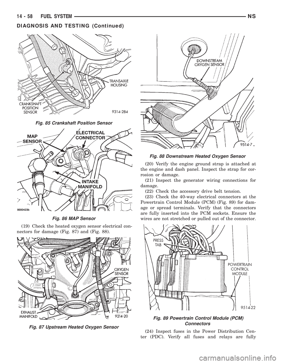
(19) Check the heated oxygen sensor electrical con-
nectors for damage (Fig. 87) and (Fig. 88).(20) Verify the engine ground strap is attached at
the engine and dash panel. Inspect the strap for cor-
rosion or damage.
(21) Inspect the generator wiring connections for
damage.
(22) Check the accessory drive belt tension.
(23) Check the 40-way electrical connectors at the
Powertrain Control Module (PCM) (Fig. 89) for dam-
age or spread terminals. Verify that the connectors
are fully inserted into the PCM sockets. Ensure the
wires are not stretched or pulled out of the connector.
(24) Inspect fuses in the Power Distribution Cen-
ter (PDC). Verify all fuses and relays are fully
Fig. 85 Crankshaft Position Sensor
Fig. 86 MAP Sensor
Fig. 87 Upstream Heated Oxygen Sensor
Fig. 88 Downstream Heated Oxygen Sensor
Fig. 89 Powertrain Control Module (PCM)
Connectors
14 - 58 FUEL SYSTEMNS
DIAGNOSIS AND TESTING (Continued)
Page 1353 of 1938
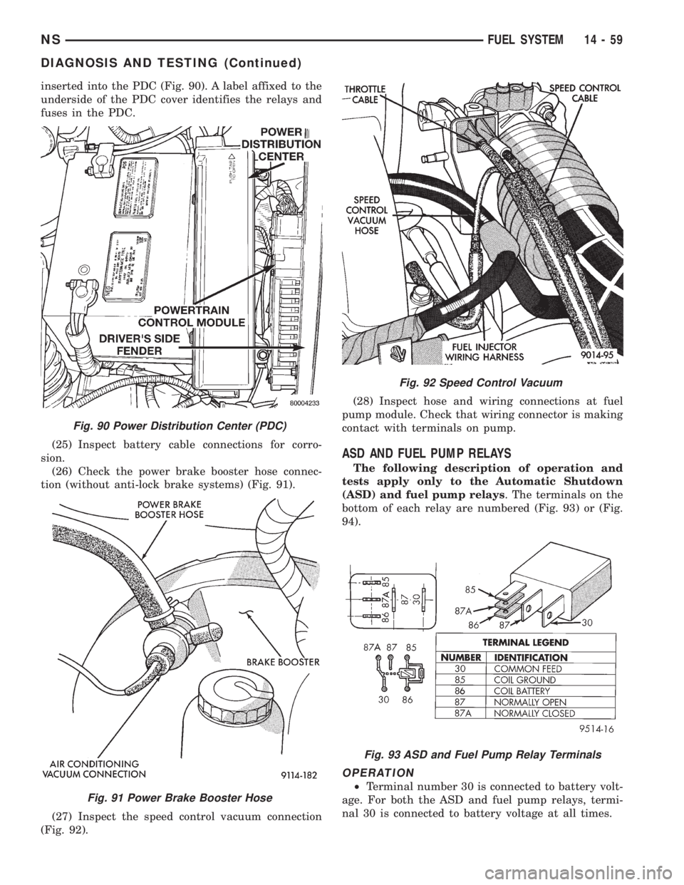
inserted into the PDC (Fig. 90). A label affixed to the
underside of the PDC cover identifies the relays and
fuses in the PDC.
(25) Inspect battery cable connections for corro-
sion.
(26) Check the power brake booster hose connec-
tion (without anti-lock brake systems) (Fig. 91).
(27) Inspect the speed control vacuum connection
(Fig. 92).(28) Inspect hose and wiring connections at fuel
pump module. Check that wiring connector is making
contact with terminals on pump.
ASD AND FUEL PUMP RELAYS
The following description of operation and
tests apply only to the Automatic Shutdown
(ASD) and fuel pump relays. The terminals on the
bottom of each relay are numbered (Fig. 93) or (Fig.
94).
OPERATION
²Terminal number 30 is connected to battery volt-
age. For both the ASD and fuel pump relays, termi-
nal 30 is connected to battery voltage at all times.
Fig. 90 Power Distribution Center (PDC)
Fig. 91 Power Brake Booster Hose
Fig. 92 Speed Control Vacuum
Fig. 93 ASD and Fuel Pump Relay Terminals
NSFUEL SYSTEM 14 - 59
DIAGNOSIS AND TESTING (Continued)
Page 1354 of 1938
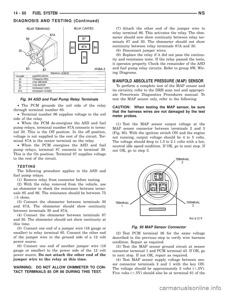
²The PCM grounds the coil side of the relay
through terminal number 85.
²Terminal number 86 supplies voltage to the coil
side of the relay.
²When the PCM de-energizes the ASD and fuel
pump relays, terminal number 87A connects to termi-
nal 30. This is the Off position. In the off position,
voltage is not supplied to the rest of the circuit. Ter-
minal 87A is the center terminal on the relay.
²When the PCM energizes the ASD and fuel
pump relays, terminal 87 connects to terminal 30.
This is the On position. Terminal 87 supplies voltage
to the rest of the circuit.
TESTING
The following procedure applies to the ASD and
fuel pump relays.
(1) Remove relay from connector before testing.
(2) With the relay removed from the vehicle, use
an ohmmeter to check the resistance between termi-
nals 85 and 86. The resistance should be between 75
65 ohms.
(3) Connect the ohmmeter between terminals 30
and 87A. The ohmmeter should show continuity
between terminals 30 and 87A.
(4) Connect the ohmmeter between terminals 87
and 30. The ohmmeter should not show continuity at
this time.
(5) Connect one end of a jumper wire (16 gauge or
smaller) to relay terminal 85. Connect the other end
of the jumper wire to the ground side of a 12 volt
power source.
(6) Connect one end of another jumper wire (16
gauge or smaller) to the power side of the 12 volt
power source.Do not attach the other end of the
jumper wire to the relay at this time.
WARNING: DO NOT ALLOW OHMMETER TO CON-
TACT TERMINALS 85 OR 86 DURING THIS TEST.(7) Attach the other end of the jumper wire to
relay terminal 86. This activates the relay. The ohm-
meter should now show continuity between relay ter-
minals 87 and 30. The ohmmeter should not show
continuity between relay terminals 87A and 30.
(8) Disconnect jumper wires.
(9) Replace the relay if it did not pass the continu-
ity and resistance tests. If the relay passed the tests,
it operates properly. Check the remainder of the ASD
and fuel pump relay circuits. Refer to group 8W, Wir-
ing Diagrams.
MANIFOLD ABSOLUTE PRESSURE (MAP) SENSOR
To perform a complete test of the MAP sensor and
its circuitry, refer to the DRB scan tool and appropri-
ate Powertrain Diagnostics Procedures manual. To
test the MAP sensor only, refer to the following:
CAUTION: When testing the MAP sensor, be sure
that the harness wires are not damaged by the test
meter probes.
(1) Test the MAP sensor output voltage at the
MAP sensor connector between terminals 2 and 3
(Fig. 95). With the ignition switch ON and the engine
not running, output voltage should be 4 to 5 volts.
The voltage should drop to 1.5 to 2.1 volts with a hot,
neutral idle speed condition. If OK, go to next step. If
not OK, go to step 3.
(2) Test PCM terminal 36 for the same voltage
described in the previous step to verify wire harness
condition. Repair as required.
(3) Test the MAP sensor ground circuit at sensor
connector terminal 1 and PCM terminal 43. If OK, go
to next step. If not OK, repair as required.
(4) Test MAP sensor supply voltage between sen-
sor connector terminals 2 and 1 with the key ON.
The voltage should be approximately 5 volts (6.5V).
Five volts (6.5V) should also be at terminal 61 of the
Fig. 94 ASD and Fuel Pump Relay Terminals
Fig. 95 MAP Sensor Connector
14 - 60 FUEL SYSTEMNS
DIAGNOSIS AND TESTING (Continued)
Page 1358 of 1938
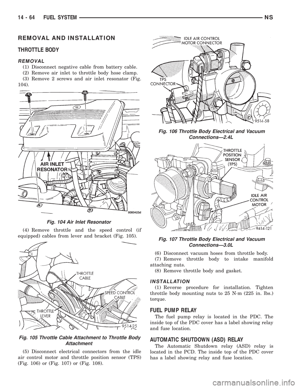
REMOVAL AND INSTALLATION
THROTTLE BODY
REMOVAL
(1) Disconnect negative cable from battery cable.
(2) Remove air inlet to throttle body hose clamp.
(3) Remove 2 screws and air inlet resonator (Fig.
104).
(4) Remove throttle and the speed control (if
equipped) cables from lever and bracket (Fig. 105).
(5) Disconnect electrical connectors from the idle
air control motor and throttle position sensor (TPS)
(Fig. 106) or (Fig. 107) or (Fig. 108).(6) Disconnect vacuum hoses from throttle body.
(7) Remove throttle body to intake manifold
attaching nuts.
(8) Remove throttle body and gasket.
INSTALLATION
(1) Reverse procedure for installation. Tighten
throttle body mounting nuts to 25 N´m (225 in. lbs.)
torque.
FUEL PUMP RELAY
The fuel pump relay is located in the PDC. The
inside top of the PDC cover has a label showing relay
and fuse location.
AUTOMATIC SHUTDOWN (ASD) RELAY
The Automatic Shutdown relay (ASD) relay is
located in the PCD. The inside top of the PDC cover
has a label showing relay and fuse location.
Fig. 104 Air Inlet Resonator
Fig. 105 Throttle Cable Attachment to Throttle Body
Attachment
Fig. 106 Throttle Body Electrical and Vacuum
ConnectionsÐ2.4L
Fig. 107 Throttle Body Electrical and Vacuum
ConnectionsÐ3.0L
14 - 64 FUEL SYSTEMNS
Page 1369 of 1938
FUEL SYSTEMÐ2.5L DIESEL ENGINE/2.0L GAS ENGINE
CONTENTS
page page
FUEL DELIVERY SYSTEMÐ2.0L ENGINE.... 28
FUEL DELIVERY SYSTEMÐ2.5L DIESEL
ENGINE.............................. 3
FUEL INJECTION SYSTEMÐ2.0L ENGINE . . . 32FUEL INJECTION SYSTEMÐ2.5L DIESEL
ENGINE............................. 43
GENERAL INFORMATION.................. 1
GENERAL INFORMATION
INDEX
page page
GENERAL INFORMATION
FUEL REQUIREMENTSÐ2.0L ENGINE....... 2
FUEL REQUIREMENTSÐ2.5L DIESEL........ 2GASOLINE/OXYGENATE BLENDS........... 2
INTRODUCTIONÐ2.0L ENGINE............. 2
INTRODUCTIONÐ2.5L DIESEL............. 1
GENERAL INFORMATION
INTRODUCTIONÐ2.5L DIESEL
Certain components of the fuel system on the 2.5L
diesel engine are controlled by the Bosch Engine con-
troller which is a Powertrain Control Module (PCM).
Refer to Powertrain Control Module in the Fuel
Injection SystemÐ2.5L Diesel Engine section of this
group for a list of items controlled by the PCM. The
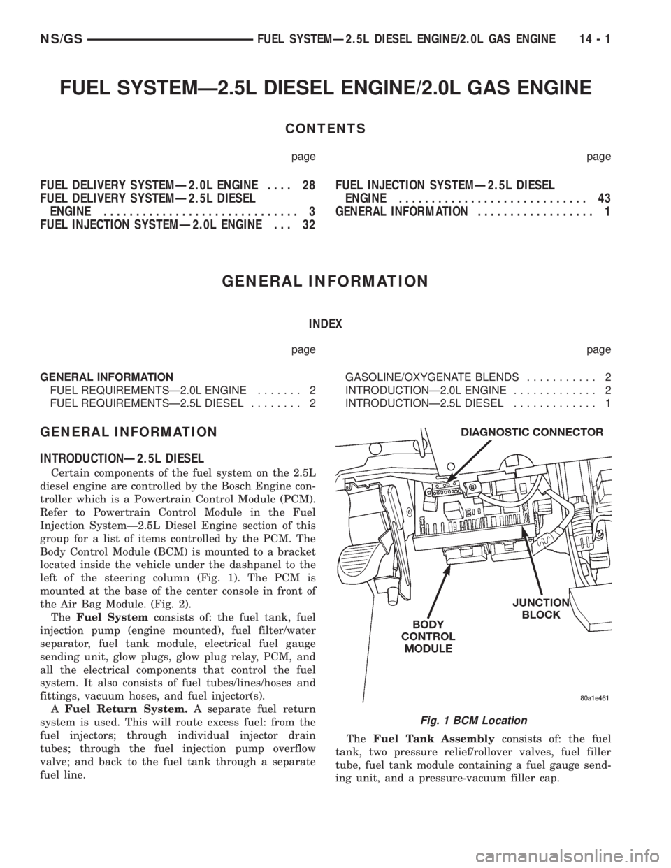
Body Control Module (BCM) is mounted to a bracket
located inside the vehicle under the dashpanel to the
left of the steering column (Fig. 1). The PCM is
mounted at the base of the center console in front of
the Air Bag Module. (Fig. 2).
TheFuel Systemconsists of: the fuel tank, fuel
injection pump (engine mounted), fuel filter/water
separator, fuel tank module, electrical fuel gauge
sending unit, glow plugs, glow plug relay, PCM, and
all the electrical components that control the fuel
system. It also consists of fuel tubes/lines/hoses and
fittings, vacuum hoses, and fuel injector(s).
AFuel Return System.A separate fuel return
system is used. This will route excess fuel: from the
fuel injectors; through individual injector drain
tubes; through the fuel injection pump overflow
valve; and back to the fuel tank through a separate
fuel line.TheFuel Tank Assemblyconsists of: the fuel
tank, two pressure relief/rollover valves, fuel filler
tube, fuel tank module containing a fuel gauge send-
ing unit, and a pressure-vacuum filler cap.
Fig. 1 BCM Location
NS/GSFUEL SYSTEMÐ2.5L DIESEL ENGINE/2.0L GAS ENGINE 14 - 1