height adjustment CHRYSLER VOYAGER 1996 Owner's Manual
[x] Cancel search | Manufacturer: CHRYSLER, Model Year: 1996, Model line: VOYAGER, Model: CHRYSLER VOYAGER 1996Pages: 1938, PDF Size: 55.84 MB
Page 1257 of 1938

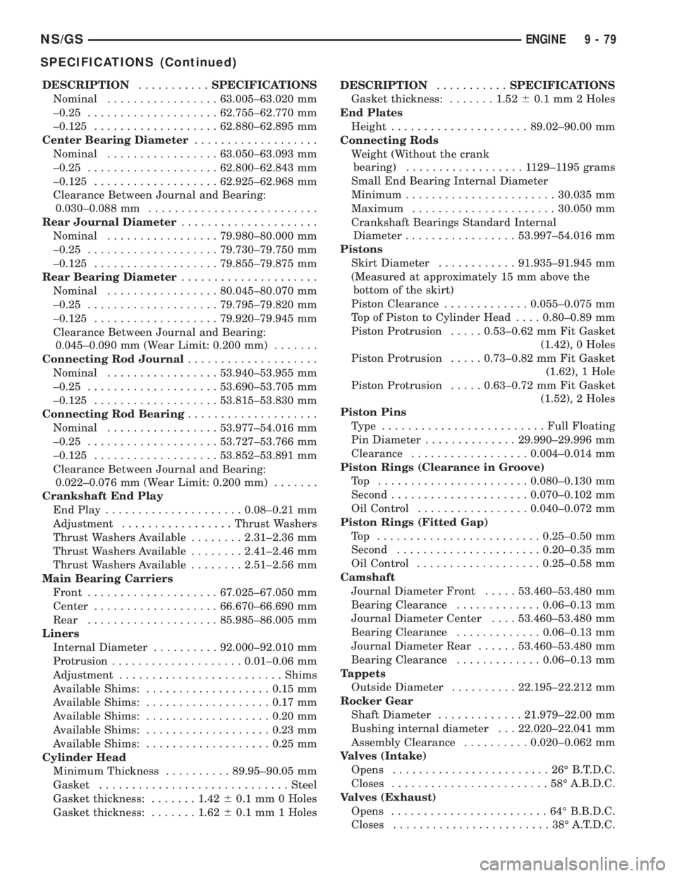
DESCRIPTION...........SPECIFICATIONS
Nominal.................63.005±63.020 mm
±0.25....................62.755±62.770 mm
±0.125...................62.880±62.895 mm
Center Bearing Diameter...................
Nominal.................63.050±63.093 mm
±0.25....................62.800±62.843 mm
±0.125...................62.925±62.968 mm
Clearance Between Journal and Bearing:
0.030±0.088 mm..........................
Rear Journal Diameter.....................
Nominal.................79.980±80.000 mm
±0.25....................79.730±79.750 mm
±0.125...................79.855±79.875 mm
Rear Bearing Diameter.....................
Nominal.................80.045±80.070 mm
±0.25....................79.795±79.820 mm
±0.125...................79.920±79.945 mm
Clearance Between Journal and Bearing:
0.045±0.090 mm (Wear Limit: 0.200 mm).......
Connecting Rod Journal....................
Nominal.................53.940±53.955 mm
±0.25....................53.690±53.705 mm
±0.125...................53.815±53.830 mm
Connecting Rod Bearing....................
Nominal.................53.977±54.016 mm
±0.25....................53.727±53.766 mm
±0.125...................53.852±53.891 mm
Clearance Between Journal and Bearing:
0.022±0.076 mm (Wear Limit: 0.200 mm).......
Crankshaft End Play
End Play.....................0.08±0.21 mm
Adjustment.................Thrust Washers
Thrust Washers Available........2.31±2.36 mm
Thrust Washers Available........2.41±2.46 mm
Thrust Washers Available........2.51±2.56 mm
Main Bearing Carriers
Front....................67.025±67.050 mm
Center...................66.670±66.690 mm
Rear....................85.985±86.005 mm
Liners
Internal Diameter..........92.000±92.010 mm
Protrusion....................0.01±0.06 mm
Adjustment.........................Shims
Available Shims:...................0.15 mm
Available Shims:...................0.17 mm
Available Shims:...................0.20 mm
Available Shims:...................0.23 mm
Available Shims:...................0.25 mm
Cylinder Head
Minimum Thickness..........89.95±90.05 mm
Gasket.............................Steel
Gasket thickness:.......1.4260.1 mm 0 Holes
Gasket thickness:.......1.6260.1 mm 1 HolesDESCRIPTION...........SPECIFICATIONS
Gasket thickness:.......1.5260.1 mm 2 Holes
End Plates
Height.....................89.02±90.00 mm
Connecting Rods
Weight (Without the crank
bearing)..................1129±1195 grams
Small End Bearing Internal Diameter
Minimum.......................30.035 mm
Maximum......................30.050 mm
Crankshaft Bearings Standard Internal
Diameter.................53.997±54.016 mm
Pistons
Skirt Diameter............91.935±91.945 mm
(Measured at approximately 15 mm above the
bottom of the skirt)
Piston Clearance.............0.055±0.075 mm
Top of Piston to Cylinder Head....0.80±0.89 mm
Piston Protrusion.....0.53±0.62 mm Fit Gasket
(1.42), 0 Holes
Piston Protrusion.....0.73±0.82 mm Fit Gasket
(1.62), 1 Hole
Piston Protrusion.....0.63±0.72 mm Fit Gasket
(1.52), 2 Holes
Piston Pins
Type .........................Full Floating
Pin Diameter..............29.990±29.996 mm
Clearance..................0.004±0.014 mm
Piston Rings (Clearance in Groove)
Top .......................0.080±0.130 mm
Second.....................0.070±0.102 mm
Oil Control.................0.040±0.072 mm
Piston Rings (Fitted Gap)
Top .........................0.25±0.50 mm
Second......................0.20±0.35 mm
Oil Control...................0.25±0.58 mm
Camshaft
Journal Diameter Front.....53.460±53.480 mm
Bearing Clearance.............0.06±0.13 mm
Journal Diameter Center....53.460±53.480 mm
Bearing Clearance.............0.06±0.13 mm
Journal Diameter Rear......53.460±53.480 mm
Bearing Clearance.............0.06±0.13 mm
Tappets
Outside Diameter..........22.195±22.212 mm
Rocker Gear
Shaft Diameter.............21.979±22.00 mm
Bushing internal diameter . . . 22.020±22.041 mm
Assembly Clearance..........0.020±0.062 mm
Valves (Intake)
Opens........................26ÉB.T.D.C.
Closes........................58ÉA.B.D.C.
Valves (Exhaust)
Opens........................64ÉB.B.D.C.
Closes........................38ÉA.T.D.C.
NS/GSENGINE 9 - 79
SPECIFICATIONS (Continued)
Page 1753 of 1938

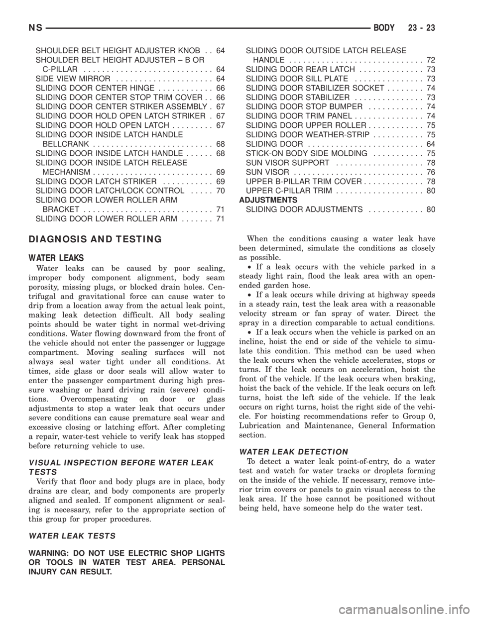
SHOULDER BELT HEIGHT ADJUSTER KNOB . . 64
SHOULDER BELT HEIGHT ADJUSTER±BOR
C-PILLAR............................ 64
SIDE VIEW MIRROR..................... 64
SLIDING DOOR CENTER HINGE............ 66
SLIDING DOOR CENTER STOP TRIM COVER . . 66
SLIDING DOOR CENTER STRIKER ASSEMBLY . 67
SLIDING DOOR HOLD OPEN LATCH STRIKER . 67
SLIDING DOOR HOLD OPEN LATCH......... 67
SLIDING DOOR INSIDE LATCH HANDLE
BELLCRANK.......................... 68
SLIDING DOOR INSIDE LATCH HANDLE...... 68
SLIDING DOOR INSIDE LATCH RELEASE
MECHANISM.......................... 69
SLIDING DOOR LATCH STRIKER........... 69
SLIDING DOOR LATCH/LOCK CONTROL..... 70
SLIDING DOOR LOWER ROLLER ARM
BRACKET............................ 71
SLIDING DOOR LOWER ROLLER ARM....... 71SLIDING DOOR OUTSIDE LATCH RELEASE
HANDLE............................. 72
SLIDING DOOR REAR LATCH.............. 73
SLIDING DOOR SILL PLATE............... 73
SLIDING DOOR STABILIZER SOCKET........ 74
SLIDING DOOR STABILIZER............... 73
SLIDING DOOR STOP BUMPER............ 74
SLIDING DOOR TRIM PANEL............... 74
SLIDING DOOR UPPER ROLLER............ 75
SLIDING DOOR WEATHER-STRIP........... 75
SLIDING DOOR......................... 64
STICK-ON BODY SIDE MOLDING........... 75
SUN VISOR SUPPORT................... 78
SUN VISOR............................ 76
UPPER B-PILLAR TRIM COVER............. 78
UPPER C-PILLAR TRIM................... 80
ADJUSTMENTS
SLIDING DOOR ADJUSTMENTS............ 80
DIAGNOSIS AND TESTING
WATER LEAKS
Water leaks can be caused by poor sealing,
improper body component alignment, body seam
porosity, missing plugs, or blocked drain holes. Cen-
trifugal and gravitational force can cause water to
drip from a location away from the actual leak point,
making leak detection difficult. All body sealing
points should be water tight in normal wet-driving
conditions. Water flowing downward from the front of
the vehicle should not enter the passenger or luggage
compartment. Moving sealing surfaces will not
always seal water tight under all conditions. At
times, side glass or door seals will allow water to
enter the passenger compartment during high pres-
sure washing or hard driving rain (severe) condi-
tions. Overcompensating on door or glass
adjustments to stop a water leak that occurs under
severe conditions can cause premature seal wear and
excessive closing or latching effort. After completing
a repair, water-test vehicle to verify leak has stopped
before returning vehicle to use.
VISUAL INSPECTION BEFORE WATER LEAK
TESTS
Verify that floor and body plugs are in place, body
drains are clear, and body components are properly
aligned and sealed. If component alignment or seal-
ing is necessary, refer to the appropriate section of
this group for proper procedures.
WATER LEAK TESTS
WARNING: DO NOT USE ELECTRIC SHOP LIGHTS
OR TOOLS IN WATER TEST AREA. PERSONAL
INJURY CAN RESULT.When the conditions causing a water leak have
been determined, simulate the conditions as closely
as possible.
²If a leak occurs with the vehicle parked in a
steady light rain, flood the leak area with an open-
ended garden hose.
²If a leak occurs while driving at highway speeds
in a steady rain, test the leak area with a reasonable
velocity stream or fan spray of water. Direct the
spray in a direction comparable to actual conditions.
²If a leak occurs when the vehicle is parked on an
incline, hoist the end or side of the vehicle to simu-
late this condition. This method can be used when
the leak occurs when the vehicle accelerates, stops or
turns. If the leak occurs on acceleration, hoist the
front of the vehicle. If the leak occurs when braking,
hoist the back of the vehicle. If the leak occurs on left
turns, hoist the left side of the vehicle. If the leak
occurs on right turns, hoist the right side of the vehi-
cle. For hoisting recommendations refer to Group 0,
Lubrication and Maintenance, General Information
section.
WATER LEAK DETECTION
To detect a water leak point-of-entry, do a water
test and watch for water tracks or droplets forming
on the inside of the vehicle. If necessary, remove inte-
rior trim covers or panels to gain visual access to the
leak area. If the hose cannot be positioned without
being held, have someone help do the water test.
NSBODY 23 - 23
Page 1810 of 1938

UPPER C-PILLAR TRIM
REMOVAL
(1) Remove quarter trim bolster.
(2) Remove seat belt turning loop from height
adjuster.
(3) Remove screw holding C-pillar trim panel to
C-pillar on right side of SWB vehicle.
(4) Disengage hidden clips holding trim to upper
C-pillar.
(5) Remove upper C-pillar trim from vehicle.
INSTALLATION
(1) Place upper C-pillar trim in position on vehicle.
(2) Engage hidden clips to hold trim to upper
C-pillar.
(3) Install screw to hold C-pillar trim panel to
C-pillar on right side of SWB vehicle.
(4) Install seat belt turning loop onto height
adjuster. Tighten all seat belt bolts to 39 N´m (29 in.
lbs.) torque.
(5) Install quarter trim bolster.
ADJUSTMENTS
SLIDING DOOR ADJUSTMENTS
PRELIMINARY CHECKS
(1) Close sliding door, visually checking C-post
striker alignment entry into latch. Striker at this
point must not affect alignment.(2) On vehicles with left sliding doors, check the
fuel door blocker striker entry into latch. Striker at
this point must not affect alignment.
(3) Check C-post and B-post for door to aperture
gaps and door to door gaps. All gaps should be 5 mm
61 mm.
(4) C
heck door for height using character lines as a
reference. Also check roof contour as a controlling factor.
UP/DOWN ADJUSTMENT
(1) Visually inspect the sliding door for fitting low
at the rear of the door by checking the alignment of
the belt line of the door to quarter panel.
(2) Fully open the sliding door.
(3) Verify that all center hinge bolts are tight.
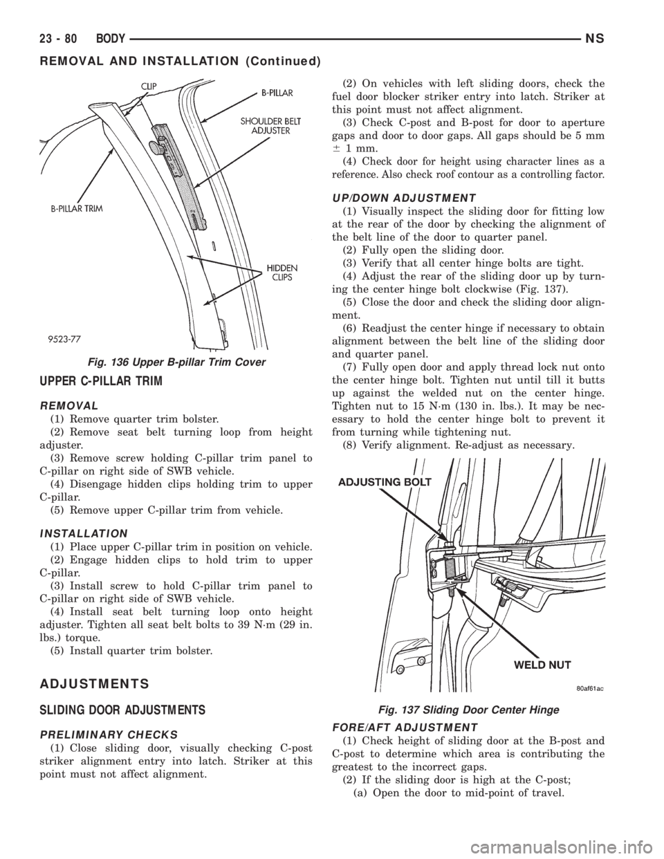
(4) Adjust the rear of the sliding door up by turn-
ing the center hinge bolt clockwise (Fig. 137).
(5) Close the door and check the sliding door align-
ment.
(6) Readjust the center hinge if necessary to obtain
alignment between the belt line of the sliding door
and quarter panel.
(7) Fully open door and apply thread lock nut onto
the center hinge bolt. Tighten nut until till it butts
up against the welded nut on the center hinge.
Tighten nut to 15 N´m (130 in. lbs.). It may be nec-
essary to hold the center hinge bolt to prevent it
from turning while tightening nut.
(8) Verify alignment. Re-adjust as necessary.
FORE/AFT ADJUSTMENT
(1) Check height of sliding door at the B-post and
C-post to determine which area is contributing the
greatest to the incorrect gaps.
(2) If the sliding door is high at the C-post;
(a) Open the door to mid-point of travel.
Fig. 136 Upper B-pillar Trim Cover
Fig. 137 Sliding Door Center Hinge
23 - 80 BODYNS
REMOVAL AND INSTALLATION (Continued)