remote start CHRYSLER VOYAGER 1996 Service Manual
[x] Cancel search | Manufacturer: CHRYSLER, Model Year: 1996, Model line: VOYAGER, Model: CHRYSLER VOYAGER 1996Pages: 1938, PDF Size: 55.84 MB
Page 267 of 1938

²Body Control Module
²Remote Keyless Entry Module
(8) Disconnect one component at time, to see if any
component is at fault. If the high reading is not elim-
inated there is a short circuit in the wiring. Refer to
Group 8W, wiring diagrams.
(9) Remove interior and brake lamp fuses. Install
the fuses. The milliampere reading should be 2-4 mA.
If reading is higher than 4 mA:
(a) Disconnect PCM.
(b) If reading is OK, replace PCM.
(c) If reading does not change there is a short
circuit to the PCM. Refer to Group 8W, Wiring Dia-
grams.
BATTERY LOAD TEST
A fully charged battery must have cranking capac-
ity, to provide the starter motor and ignition system
enough power to start the engine over a broad range
of ambient temperatures. A battery load test will ver-
ify the actual cranking capability of the battery.
WARNING: IF BATTERY SHOWS SIGNS OF FREEZ-
ING, LEAKING, LOOSE POSTS, OR EXCESSIVELY
LOW ELECTROLYTE LEVEL, DO NOT TEST. ACID
BURNS OR AN EXPLOSIVE CONDITION MAY
RESULT.
(1) Remove both battery cables, negative cable
first. The battery top, cables and posts should be
clean. Test battery with a hydrometer. If battery
charge is low the charge battery. Refer to Battery
Charging Procedures.(2) Connect a Volt/Ammeter/Load tester to the bat-
tery posts (Fig. 6). Rotate the load control knob of the
Carbon pile rheostat to apply a 300 amp load. Apply
this load for 15 seconds to remove the surface charge
from the battery, and return the control knob to off
(Fig. 7).
(3) Allow the battery to stabilize for 2 minutes,
and then verify open circuit voltage.
(4) Rotate the load control knob on the tester to
maintain 50% of the battery cold crank rating for 15
seconds (Fig. 8). Record the loaded voltage reading
and return the load control to off. Refer to the Bat-
tery Specifications at the rear of this Group.
(5) Voltage drop will vary according to battery
temperature at the time of the load test. Battery
temperature can be estimated by the temperature of
exposure over the preceding several hours. If the bat-
tery has been charged or boosted a few minutes prior
to the test, the battery would be slightly warmer.
Refer to Load Test Voltage Chart for proper loaded
voltage reading.
Fig. 5 Milliampere Meter ConnectionFig. 6 Volt-Ammeter Load Tester Connections
Fig. 7 Remove Surface Charge From Battery
NS/GSBATTERY 8A - 5
DIAGNOSIS AND TESTING (Continued)
Page 274 of 1938
²Transmission range sensor, or Park/Neutral
Position switch with automatic transmissions
²Clutch Pedal Position Switch with manual
transmissions
²Ignition switch
²Battery
²All related wiring and connections
CAUTION: Before performing any starter tests, the
ignition and fuel systems must be disabled.
²To disable ignition and fuel systems, disconnect
the Automatic Shutdown Relay (ASD). The ASD relay
is located in the in the Power Distribution Center
(PDC). Refer to the PDC cover for the proper relay
location.
STARTER SOLENOID
WARNING: CHECK TO ENSURE THAT THE TRANS-
MISSION IS IN THE PARK POSITION WITH THE
PARKING BRAKE APPLIED
(1) Verify battery condition. Battery must be in
good condition with a full charge before performing
any starter tests. Refer to Battery Tests.
(2) Perform Starter Solenoid test BEFORE per-
forming the starter relay test.
(3) Raise the vehicle.
(4) Perform a visual inspection of the starter/
starter solenoid for corrosion, loose connections or
faulty wiring.
(5) Lower the vehicle.
(6) Locate and remove the starter relay from the
Power Distribution Center (PDC). Refer to the PDC
label for relay identification and location.
(7) Connect a remote starter switch or a jumper
wire between the remote battery positive post and
terminal 87 of the starter relay connector.
(a) If engine cranks, starter/starter solenoid is
good. Go to the Starter Relay Test.
(b) If engine does not or solenoid chatters, check
wiring and connectors from starter relay to starter
solenoid for loose or corroded connections. Particu-
larly at starter terminals.
(c) Repeat test. If engine still fails to crank prop-
erly, trouble is within starter or starter mounted
solenoid, and replace starter.
STARTER RELAY
WARNING: CHECK TO ENSURE THAT THE TRANS-
MISSION IS IN THE PARK POSITION/NEUTRAL
WITH THE PARKING BRAKE APPLIED
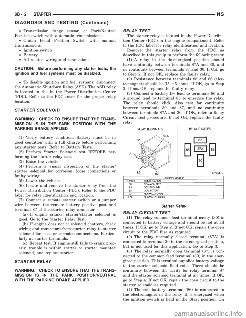
RELAY TEST
The starter relay is located in the Power Distribu-
tion Center (PDC) in the engine compartment. Refer
to the PDC label for relay identification and location.
Remove the starter relay from the PDC as
described in this group to perform the following tests:
(1) A relay in the de-energized position should
have continuity between terminals 87A and 30, and
no continuity between terminals 87 and 30. If OK, go
to Step 2. If not OK, replace the faulty relay.
(2) Resistance between terminals 85 and 86 (elec-
tromagnet) should be 7565 ohms. If OK, go to Step
3. If not OK, replace the faulty relay.
(3) Connect a battery B+ lead to terminals 86 and
a ground lead to terminal 85 to energize the relay.
The relay should click. Also test for continuity
between terminals 30 and 87, and no continuity
between terminals 87A and 30. If OK, refer to Relay
Circuit Test procedure. If not OK, replace the faulty
relay.
RELAY CIRCUIT TEST
(1) The relay common feed terminal cavity (30) is
connected to battery voltage and should be hot at all
times. If OK, go to Step 2. If not OK, repair the open
circuit to the PDC fuse as required.
(2) The relay normally closed terminal (87A) is
connected to terminal 30 in the de-energized position,
but is not used for this application. Go to Step 3.
(3) The relay normally open terminal (87) is con-
nected to the common feed terminal (30) in the ener-
gized position. This terminal supplies battery voltage
to the starter solenoid field coils. There should be
continuity between the cavity for relay terminal 87
and the starter solenoid terminal at all times. If OK,
go to Step 4. If not OK, repair the open circuit to the
starter solenoid as required.
(4) The coil battery terminal (86) is connected to
the electromagnet in the relay. It is energized when
the ignition switch is held in the Start position. On
Starter Relay
8B - 2 STARTERNS
DIAGNOSIS AND TESTING (Continued)
Page 581 of 1938
8W-10 POWER DISTRIBUTION
Component Page
A/C Compressor Clutch........................8W-10-29
A/C Compressor Clutch Relay................8W-10-10, 25, 29
Airbag Control Module........................8W-10-35
Automatic Shut Down Relay....................8W-10-9, 23
Battery.............................8W-10-8, 27, 28
Body Control Module...........8W-10-11, 14, 16, 17, 19, 21, 30, 32
BS15..................................8W-10-33
BS16..................................8W-10-34
BS19..................................8W-10-30
BS33..................................8W-10-25
Center Dome Lamp..........................8W-10-21
Cigar/Accessory Relay......................8W-10-10, 31
Clockspring..............................8W-10-30
Combination Flasher/DRL Module................8W-10-29, 32
Controller Anti-Lock Brake....................8W-10-15, 29
Courtesy Lamp Relay.........................8W-10-21
Crank Case Heater..........................8W-10-27
CS01..................................8W-10-21
CS02..................................8W-10-20
CS1 ..................................8W-10-21
Data Link Connector.........................8W-10-11
Diesel Power Relay.......................8W-10-9, 25, 29
Door Lock Relay............................8W-10-13
Door Unlock Relay..........................8W-10-13
Downstream Heated Oxygen Sensor.................8W-10-23
Driver Door Courtesy Lamp.....................8W-10-21
Driver Door Unlock Relay......................8W-10-13
Driver Power Mirror.......................8W-10-12, 22
EGR Solenoid.............................8W-10-25
Engine Starter Motor.......................8W-10-8, 16
Engine Starter Motor Relay....................8W-10-8, 16
ES01................................8W-10-27, 28
ES06................................8W-10-25, 29
ES07..................................8W-10-29
ES09..................................8W-10-8
ES11 ................................8W-10-8, 28
ES12..................................8W-10-23
ES26..................................8W-10-8
ES28..................................8W-10-8
ES29................................8W-10-25, 29
ES40..................................8W-10-27
ES99..................................8W-10-24
Fog Lamp Relay............................8W-10-33
Front Blower Motor..........................8W-10-18
Front Blower Motor Relay.....................8W-10-8, 18
Front Cigar Lighter/Power Outlet..................8W-10-31
Front Reading Lamps/Switch.....................8W-10-20
Front Wiper Switch..........................8W-10-19
FS01..................................8W-10-24
FS03..................................8W-10-23
Fuel Heater..............................8W-10-27
Fuel Heater Relay.........................8W-10-9, 27
Fuel Injector No. 1........................8W-10-23, 24
Fuel Injector No. 2........................8W-10-23, 24
Fuel Injector No. 3........................8W-10-23, 24
Fuel Injector No. 4........................8W-10-23, 24
Fuel Injector No. 5..........................8W-10-24
Fuel Injector No. 6..........................8W-10-24
Fuel Pump Module..........................8W-10-25
Fuel Pump Relay..........................8W-10-9, 26
Fuel Tank Module...........................8W-10-26
Fuse 1 (JB)..............................8W-10-17
Fuse 1 (PDC)...........................8W-10-14, 35
Fuse 2 (JB)............................8W-10-11, 16
Fuse 2 (PDC).............................8W-10-35
Fuse 3 (JB)..............................8W-10-17
Fuse 4 (JB)..............................8W-10-17
Fuse 4 (PDC).......................8W-10-10, 32, 33, 34
Fuse 5 (JB)..............................8W-10-17
Fuse 5 (PDC).......................8W-10-10, 32, 33, 34
Fuse 6 (JB)..............................8W-10-16
Fuse 6 (PDC).......................8W-10-10, 32, 33, 34
Fuse 7 (JB)..............................8W-10-12
Fuse 7 (PDC).......................8W-10-10, 32, 33, 34
Fuse 8 (JB)..............................8W-10-16
Fuse 8 (PDC)...........................8W-10-10, 31
Fuse 9 (JB)..............................8W-10-16
Fuse 9 (PDC)...........................8W-10-10, 30
Fuse 10 (JB)..............................8W-10-16
Fuse 10 (PDC)...........................8W-10-10, 29
Fuse 11 (JB)..............................8W-10-14
Fuse 11 (PDC)...........................8W-10-10, 29
Fuse 12 (JB)............................8W-10-14, 18
Fuse 12 (PDC)...........................8W-10-10, 29
Fuse 13 (PDC)...........................8W-10-10, 29
Fuse 15 (PDC)...........................8W-10-9, 28
Fuse 16 (JB)..............................8W-10-27
Fuse 16 (PDC)...........................8W-10-9, 26
Fuse 17 (PDC).......................8W-10-9, 23, 25, 29
Fuse 18 (PDC)...........................8W-10-9, 20Component Page
Fuse 19 (PDC)...........................8W-10-8, 19
Fuse 20 (PDC)...........................8W-10-8, 19
Fuse 21 (PDC)...........................8W-10-8, 18
Fuse 22 (PDC)...........................8W-10-8, 17
Fuse 23 (PDC)...........................8W-10-8, 16
Fuse 24 (PDC)...........................8W-10-8, 15
Fuse 25 (PDC)...........................8W-10-8, 15
Fuse 26 (PDC)...........................8W-10-8, 13
Fuse 27 (PDC)...........................8W-10-8, 12
Fuse 28 (PDC)...........................8W-10-9, 11
Fusible Link A11............................8W-10-8
Fusible Link A54............................8W-10-8
G100................................8W-10-27, 28
G103................................8W-10-27, 28
G200................................8W-10-14, 32
G300............................8W-10-14, 18, 19, 31
Generator............................8W-10-8, 23, 25
Glove Box Lamp............................8W-10-20
Glow Plug Relay..........................8W-10-8, 25
Headlamp Dimmer Switch......................8W-10-32
Headlamp Switch.........................8W-10-21, 34
High Beam Relay.....................8W-10-10, 32, 33, 34
High Note Horn............................8W-10-30
Horn Relay............................8W-10-10, 30
Horn Switch..............................8W-10-30
HS6D S02...............................8W-10-13
Ignition Coil Pack...........................8W-10-23
Ignition Switch........................8W-10-11, 14, 16
Instrument Cluster........................8W-10-11, 14
Junction Block..........8W-10-11, 12, 13, 14, 16, 17, 18, 20, 21, 22,
26, 27, 29, 30, 31, 32, 35
Key-In Halo Lamp..........................8W-10-21
Left Headlamp..........................8W-10-33, 34
Left Headlamp Leveling Motor....................8W-10-34
Left High Headlamp.........................8W-10-33
Left Liftgate Flood Lamp.......................8W-10-21
Left Mid Reading Lamp.....................8W-10-20, 21
Left Rear Reading Lamp.....................8W-10-20, 21
Left Visor/Vanity Mirror Lamps...................8W-10-20
Low Beam Relay.....................8W-10-10, 32, 33, 34
Low Note Horn............................8W-10-30
Memory Seat/Mirror Module.....................8W-10-11
Message Center......................8W-10-11, 14, 33, 34
Name Brand Speaker Relay.....................8W-10-16
Park Lamp Relay..........................8W-10-8, 17
Passenger Door Courtesy Lamp...................8W-10-21
Passenger Power Mirror.....................8W-10-12, 22
Power Distribution Center .8W-10-8, 9, 10, 11, 12, 13, 14, 15, 16, 17, 18, 19,
20, 23, 25, 26, 27, 28, 29, 30, 31, 32, 33, 34, 35
Power Mirror Fold Relay.......................8W-10-22
Power Mirror Switch.........................8W-10-20
Power Mirror Unfold Relay....................8W-10-21, 22
Power Seat Circuit Breaker.....................8W-10-13
Powertrain Control Module............8W-10-16, 23, 25, 26, 27, 29
PTC 1 (JB)......................8W-10-16, 26, 27, 29, 35
PTC 3 (JB)..............................8W-10-13
PTC 7 (JB)............................8W-10-16, 31
PTC 8 (JB)..............................8W-10-16
PTC 9 (JB)..............................8W-10-16
Radiator Fan Relay..........................8W-10-15
Radiator Fan Relay No. 1.......................8W-10-25
Radiator Fan Relay No. 2.....................8W-10-15, 25
Radiator Fan Relay No. 3.....................8W-10-19, 25
Radio..................................8W-10-11
Rear Cigar Lighter/Power Outlet...................8W-10-31
Rear Dome Lamp...........................8W-10-21
Rear Window Defogger........................8W-10-12
Rear Window Defogger Relay.....................8W-10-12
Remote Keyless Entry Module....................8W-10-11
Right Headlamp..........................8W-10-33, 34
Right Headlamp Leveling Motor...................8W-10-34
Right High Headlamp.........................8W-10-33
Right Liftgate Flood Lamp......................8W-10-21
Right Low Headlamp.........................8W-10-33
Right Mid Reading Lamp.....................8W-10-20, 21
Right Rear Reading Lamp....................8W-10-20, 21
Right Visor/Vanity Mirror Lamps..................8W-10-20
Sentry Key Immobilizer Module...................8W-10-20
Stop Lamp Switch...........................8W-10-29
Transmission Control Module..................8W-10-16, 28
Transmission Control Relay....................8W-10-9, 28
Transmission Control Solenoids...................8W-10-28
Universal Garage Door Opener....................8W-10-20
Upstream Heated Oxygen Sensor..................8W-10-23
Vehicle Speed Sensor.......................8W-10-27, 29
Washer Module............................8W-10-13
Wiper High/Low Relay........................8W-10-19
Wiper Module.............................8W-10-19
Wiper On Relay..........................8W-10-8, 19
NS/GS8W - 10 POWER DISTRIBUTION 8W - 10 - 1
Page 591 of 1938

BATT A0
10A
FUSE
28CENTER DISTRIBUTION
POWER
5C3
M1
20
PK
JUNCTION
BLOCK
13C1
16
MODULE MIRROR
SEAT/
MEMORY C1
M1
20
PK
C4613C417C4
9
MODULE BODY
CONTROL
REMOTE
KEYLESS
ENTRY
MODULE
3M1
20
PK
12
CENTER MESSAGE
PK20 M1
C32
C31
3
0 2
14
SWITCH IGNITION
M1
20
PK
A81
20
DG/RD
INSTRUMENT
CLUSTER
2M1
20
PK
C1
RADIO7M1
20
PK
M1
20
PK
16
DATA LINK
CONNECTOR
BLOCK JUNCTION
10A
FUSE
2
C415
D1
D3
*8
7P50NOT
USED* RHD M1
22
PK
4 ACC 3 LOCK 0 OFF
2 RUN
1 START (8W-10-8)
(8W-10-9)
(8W-12-2) (8W-62-3)
(8W-63-4)
(8W-45-2)
(8W-61-5)(8W-46-2)
(8W-10-14) (8W-40-2)
(8W-47-2)(8W-30-3)
(8W-12-2)
(8W-12-9)
NS/GS8W-10 POWER DISTRIBUTION 8W - 10 - 11
GS001011J988W-1
(8W-30-30)
Page 617 of 1938
8W-12 JUNCTION BLOCK
Component PageA/C Compressor Clutch Relay..............8W-12-13
A/C Heater Control.................8W-12-9, 12, 23
Airbag Control Module...................8W-12-13
Ash Receiver Lamp...................8W-12-19, 23
Automatic Day/Night Mirror................8W-12-9
Back-Up Switch........................8W-12-12
Body Control Module........8W-12-8, 9, 14, 15, 17, 18,
19, 20, 22, 23, 24, 26
Brake Pressure Switch...................8W-12-17
Cigar/Accessory Relay....................8W-12-16
Clutch Interlock Switch..................8W-12-16
Clutch Interlock Switch Jumper............8W-12-16
Combination Flasher/DRL Module . . .8W-12-12, 17, 18, 19
Controller Anti-Lock Brake................8W-12-12
Courtesy Lamp Relay....................8W-12-22
CS01...............................8W-12-22
CS02...............................8W-12-21
CS04................................8W-12-9
CS1................................8W-12-22
Data Link Connector....................8W-12-20
Door Lock Relay.....................8W-12-15, 19
Door Unlock Relay...................8W-12-14, 19
Driver Door Courtesy Lamp...............8W-12-22
Driver Door Lock Motor................8W-12-14, 15
Driver Door Lock Switch..................8W-12-23
Driver Door Unlock Relay..............8W-12-14, 19
Driver Heated Seat Switch................8W-12-12
Driver Power Mirror..................8W-12-10, 26
Driver Power Window Switch............8W-12-16, 23
EGR Solenoid.........................8W-12-13
Electric Wiper De-Icer...................8W-12-11
Engine Starter Motor Relay...............8W-12-16
ES07...............................8W-12-13
ES29...............................8W-12-13
Evap Leak Detection Pump................8W-12-13
Fog Lamp Relay.......................8W-12-25
Front Blower Motor Relay.................8W-12-12
Front Cigar Lighter/Power Outlet...........8W-12-23
Front Reading Lamps/Switch..............8W-12-21
Front Washer Motor................8W-12-16, 23, 24
Front Wiper Switch................8W-12-16, 23, 24
Fuel Heater Relay......................8W-12-13
Fuel Pump Relay.......................8W-12-13
Fuse 1 (JB)............................8W-12-8
Fuse 2 (JB).........................8W-12-9, 20
Fuse 2 (PDC)..........................8W-12-13
Fuse 3 (JB)............................8W-12-8
Fuse 4 (JB)............................8W-12-8
Fuse 5 (JB).........................8W-12-8, 24
Fuse 6 (JB)............................8W-12-9
Fuse 6 (PDC)..........................8W-12-25
Fuse 7 (JB)...........................8W-12-10
Fuse 8 (JB)...........................8W-12-11
Fuse 9 (JB)...........................8W-12-11
Fuse 10 (JB)..........................8W-12-16
Fuse 11 (JB)..........................8W-12-11
Fuse 12 (JB)..........................8W-12-12
Fuse 18 (PDC).........................8W-12-26
Fuse 22 (PDC).......................8W-12-8, 24
G300..........................8W-12-11, 19, 26
Glove Box Lamp.......................8W-12-21
Headlamp Dimmer Switch..............8W-12-18, 25
Headlamp Switch.............8W-12-8, 19, 22, 23, 25
Headlamp Washer......................8W-12-24
Horn Relay...........................8W-12-17
HS2................................8W-12-12
HS4................................8W-12-12Component PageIgnition Switch...................8W-12-17, 19, 20
Instrument Cluster..............8W-12-9, 19, 20, 23
Junction Block......8W-12-2, 8, 9, 10, 11, 12, 13, 14, 15,
16, 17, 18, 19, 20, 21, 22, 23, 24, 25, 26
Key-In Halo Lamp.................8W-12-19, 22, 26
Left Combination Relay..................8W-12-18
Left Fog Lamp.......................8W-12-8, 25
Left Front Park/Turn Signal Lamp.........8W-12-8, 18
Left Liftgate Flood Lamp.................8W-12-22
Left Low Headlamp.....................8W-12-25
Left Rear Lamp Assembly...............8W-12-8, 18
Left Rear Sliding Door Contact...........8W-12-14, 15
Left Repeater Lamp.....................8W-12-18
Left Stop/Turn Signal Relay...............8W-12-18
License Lamp..........................8W-12-8
Liftgate Lock Motor..................8W-12-14, 15
Low Beam Relay.......................8W-12-25
Message Center..............8W-12-9, 17, 18, 19, 20
Name Brand Speaker Relay.............8W-12-11, 19
Overhead Console.......................8W-12-9
Park Brake Switch......................8W-12-17
Park Lamp Relay.....................8W-12-8, 24
Passenger Door Courtesy Lamp.............8W-12-22
Passenger Door Lock Motor.............8W-12-14, 15
Passenger Door Lock Switch...............8W-12-23
Passenger Heated Seat Switch..............8W-12-12
Passenger Power Mirror...............8W-12-10, 26
Passenger Power Window Switch.........8W-12-16, 23
Power Distribution Center.........8W-8,12-12, 13, 16,
17, 24, 25, 26
Power Folding Mirror Switch............8W-12-19, 26
Power Mirror Fold Relay..................8W-12-26
Power Mirror Switch...............8W-12-19, 21, 23
Power Mirror Unfold Relay................8W-12-26
Powertrain Control Module................8W-12-13
PTC 1 (JB)...........................8W-12-13
PTC 3 (JB)......................8W-12-14, 15, 24
PTC 7 (JB).........................8W-12-16, 24
PTC 8 (JB)...........................8W-12-16
PTC 9 (JB)...........................8W-12-16
Radio..........................8W-12-11, 20, 23
Radio Choke..........................8W-12-11
Rear A/C Heater Unit....................8W-12-11
Rear Blower Front Control Switch...........8W-12-23
Rear Blower Rear Control Switch...........8W-12-23
Rear Washer Motor.....................8W-12-16
Rear Window Defogger...................8W-12-10
Rear Window Defogger Relay............8W-12-10, 12
Rear Wiper Motor.......................8W-12-9
Remote Keyless Entry Module..............8W-12-20
Right Combination Relay.................8W-12-18
Right Fog Lamp......................8W-12-8, 25
Right Front Park/Turn Signal Lamp........8W-12-8, 18
Right Liftgate Flood Lamp................8W-12-22
Right Rear Lamp Assembly..............8W-12-8, 18
Right Rear Sliding Door Contact..........8W-12-14, 15
Right Repeater Lamp....................8W-12-18
Right Stop/Turn Signal Relay..............8W-12-18
Sentry Key Immobilizer Module..........8W-12-13, 21
Stop Lamp Switch......................8W-12-19
Traction Control Switch................8W-12-19, 23
Trailer Tow Connector....................8W-12-8
Transmission Control Module.............8W-12-9, 16
Transmission Range Sensor................8W-12-12
Turn Signal/Hazard Switch................8W-12-17
Universal Garage Door Opener.............8W-12-23
Washer Module.................8W-12-8, 15, 16, 23
NS/GS8W - 12 JUNCTION BLOCK 8W - 12 - 1
Page 636 of 1938

BATT M1
JUNCTION
BLOCK
C4613C417C4
9
MODULE BODY
CONTROL
REMOTE
KEYLESS
ENTRY
MODULE
3M1
20
PK
12
CENTER MESSAGE
PK20 M1
C32
C31
3
0 2
14
SWITCH IGNITION
M1
20
PK
A81
20
DG/RD
INSTRUMENT
CLUSTER
2M1
20
PK
C1
RADIO7M1
20
PK
M1
20
PK
16
DATA LINK
CONNECTOR
BLOCK JUNCTION
10A
FUSE
2
C415
D1
D31 START
2 RUN
3 LOCK 0 OFF
4 ACC
*8
* RHD
7P50NOT
USEDM1
22
PK
(8W-10-11)
(8W-12-2)
(8W-45-2)
(8W-61-5)(8W-46-2)(8W-40-2)
(8W-47-2)(8W-30-3)
(8W-12-2)
(8W-12-9)(8W-10-14)
(8W-10-16)
8W - 12 - 20 8W-12 JUNCTION BLOCKNS/GS
J988W-3GS001220
(8W-30-30)
Page 1439 of 1938
(18) Remove the 3 previously loosened bolts
attaching the front bracket to the power steering
pump and separate the power steering pump from
the front bracket prior to removing the pump from
the vehicle.
(19) The power steering pump is removed from the
vehicle by pulling it out through the exhaust tunnel
area in the floor pan of the vehicle.
INSTALL
(1) Install power steering pump back in vehicle
using the reverse order of its removal through the
exhaust tunnel are of the vehicle.
(2) Install the power steering pump on its cast
mounting bracket and loosely install nut to hold
pump in place (Fig. 9).
(3) Install the front bracket on the power steering
pump and loosely install the 3 mounting bolts (Fig.
10). Then install the nut and bolt attaching the front
bracket to the cast bracket (Fig. 10).
(4) Tighten the 3 power steering pump mounting
bolts (Fig. 10) to a torque of 54 N´m (40 ft. lbs.).
NOTE: Before installing power steering fluid pres-
sure hose on power steering pump, inspect the
O-ring on the pressure hose for damage and
replace if necessary.
(5) Install the power steering fluid pressure line
onto the output fitting of the power steering pump
(Fig. 8). Tighten the pressure line to pump fitting
tube nut to a torque of 31 N´m (275 in. lbs.).
(6) Install the power steering fluid, low pressure
return hose on the power steering pump low pressure
fitting (Fig. 8).Be sure hose clamps are properly
reinstalled.
(7) Install the power steering fluid supply hose
from the power steering fluid reservoir, on the power
steering pump fluid fitting (Fig. 7).Be sure hose is
clear of accessory drive belts all hose clamps
are properly reinstalled.
(8) Install the power steering pump drive belt on
pulley. See Cooling, Group 7 for detailed installation
procedure.
(9) Install the accessory drive splash shield (Fig.
6).
(10) Install the power steering fluid return hose on
the steel tube at the front suspension cradle (Fig. 5).
(11) Install a screw type hose clamp on the power
steering hose to steel tube connection.Be sure hose
clamps are properly reinstalled.Tighten the screw
clamp to a torque of 2 N´m (18 in. lbs.).
CAUTION: The protective heat shield sleeves must
cover the entire rubber hose and hose to tube con-
nection portion of both the power steering fluid
pressure and return hoses (Fig. 5). This is requiredto prevent the overheating of the power steering
hoses.
(12) When used, properly position the protective
heat sleeves on the power steering hoses (Fig. 5).
Then, tie strap the heat sleeves to the power steering
hoses to keep them in their proper position.
(13) Install the exhaust pipe on the exhaust man-
ifold. Install all exhaust system hangers/isolators on
the exhaust system brackets.
(14) Connect the oxygen sensor wiring harness to
the vehicle wiring harness. Install wiring harness
grommet in the floor pan of the vehicle.
(15) Lower vehicle.
(16) Adjust the power steering pump drive belt.
See Cooling, Group 7 for detailed adjustment proce-
dure.
(17) Tighten the top nut and bottom bolt on the
power steering pump front mounting bracket (Fig. 3)
to a torque of 54 N´m (40 ft. lbs.).
CAUTION: Do not use automatic transmission fluid
in power steering system. Only use MoparT, Power
Steering Fluid, or equivalent.
(18) Fill the remote power steering pump fluid res-
ervoir to correct fluid level.
(19) Install cap on power steering fluid reservoir.
(20) Connect the negative battery cable on the
negative battery post.
(21) Start engine and turn steering wheel several
times from stop to stop to bleed air from fluid in sys-
tem. Stop engine, check fluid level, and inspect sys-
tem for leaks. See Checking Fluid Level.
3.0 LITER POWER STEERING PUMP
REMOVE
WARNING: POWER STEERING OIL, ENGINE COM-
PONENTS AND THE EXHAUST SYSTEM MAY BE
EXTREMELY HOT IF ENGINE HAS BEEN RUNNING.
DO NOT START ENGINE WITH ANY LOOSE OR DIS-
CONNECTED HOSES. DO NOT ALLOW HOSES TO
TOUCH HOT EXHAUST MANIFOLD OR CATALYST.
(1) Remove the (-) negative battery cable from the
battery and isolate cable.
(2) Remove cap from power steering fluid reser-
voir.
(3) Using a siphon pump, remove as much power
steering fluid as possible from the power steering
fluid reservoir.
NSSTEERING 19 - 13
REMOVAL AND INSTALLATION (Continued)
Page 1442 of 1938
(15) Fill the remote power steering pump fluid res-
ervoir to correct fluid level.
(16) Install cap on power steering fluid reservoir.
(17) Connect the negative battery cable on the
negative battery post.
(18) Start engine and turn steering wheel several
times from stop to stop to bleed air from fluid in sys-
tem. Stop engine, check fluid level, and inspect sys-
tem for leaks. See Checking Fluid Level.
3.3/3.8 LITER POWER STEERING PUMP
REMOVE
WARNING: POWER STEERING OIL, ENGINE COM-
PONENTS AND THE EXHAUST SYSTEM MAY BE
EXTREMELY HOT IF ENGINE HAS BEEN RUNNING.
DO NOT START ENGINE WITH ANY LOOSE OR DIS-
CONNECTED HOSES. DO NOT ALLOW HOSES TO
TOUCH HOT EXHAUST MANIFOLD OR CATALYST.
(1) Remove the (-) negative battery cable from the
battery and isolate cable.
(2) Remove cap from power steering fluid reser-
voir.
(3) Using a siphon pump, remove as much power
steering fluid as possible from the power steering
fluid reservoir.
(4) Raise vehicle on jack stands or centered on a
frame contact type hoist. See Hoisting, in the Lubri-
cation and Maintenance section of this service man-
ual for the required lifting procedure.
(5) Disconnect the oxygen sensor wiring harness
from the vehicle wiring harness. Access to connection
at vehicle wiring harness is through the oxygen sen-
sor wiring harness grommet in the floor pan of the
vehicle.
NOTE: The exhaust system needs to be removed
from the engine to allow for an area to remove the
power steering pump from the vehicle.
(6) Remove the catalytic converter from the
exhaust manifold. Then remove all the exhaust sys-
tem hangers/isolators from the brackets on the
exhaust system.
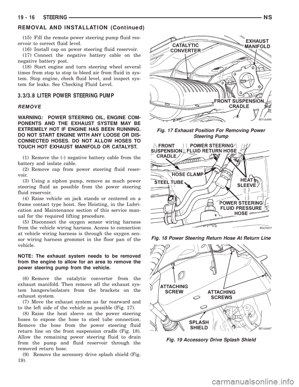
(7) Move the exhaust system as far rearward and
to the left side of the vehicle as possible (Fig. 17).
(8) Raise the heat sleeve on the power steering
hoses to expose the hose to steel tube connection.
Remove the hose from the power steering fluid
return line on the front suspension cradle (Fig. 18).
Allow the remaining power steering fluid to drain
from the pump and fluid reservoir through the
removed return hose.
(9) Remove the accessory drive splash shield (Fig.
19).
Fig. 17 Exhaust Position For Removing Power
Steering Pump
Fig. 18 Power Steering Return Hose At Return Line
Fig. 19 Accessory Drive Splash Shield
19 - 16 STEERINGNS
REMOVAL AND INSTALLATION (Continued)
Page 1444 of 1938
NOTE: Before installing power steering pressure
hose on power steering pump, inspect the O-ring
on the power steering pressure hose for damage
and replace if required.
(4) Install the power steering fluid pressure line
onto the output fitting of the power steering pump
(Fig. 21). Tighten the pressure line to pump fitting
tube nut to a torque of 31 N´m (275 in. lbs.).
(5) Install the power steering fluid, low pressure
return hose on the power steering pump low pressure
fitting (Fig. 21).Be sure hose clamps are prop-
erly reinstalled.
(6) Install the power steering fluid supply hose
from the power steering fluid reservoir, on the power
steering pump fluid fitting (Fig. 21).Be sure hose is
clear of accessory drive belts and all hose
clamps are properly reinstalled.
(7) Install the serpentine drive belt (Fig. 20). See
Cooling, Group 7 for detailed installation procedure.
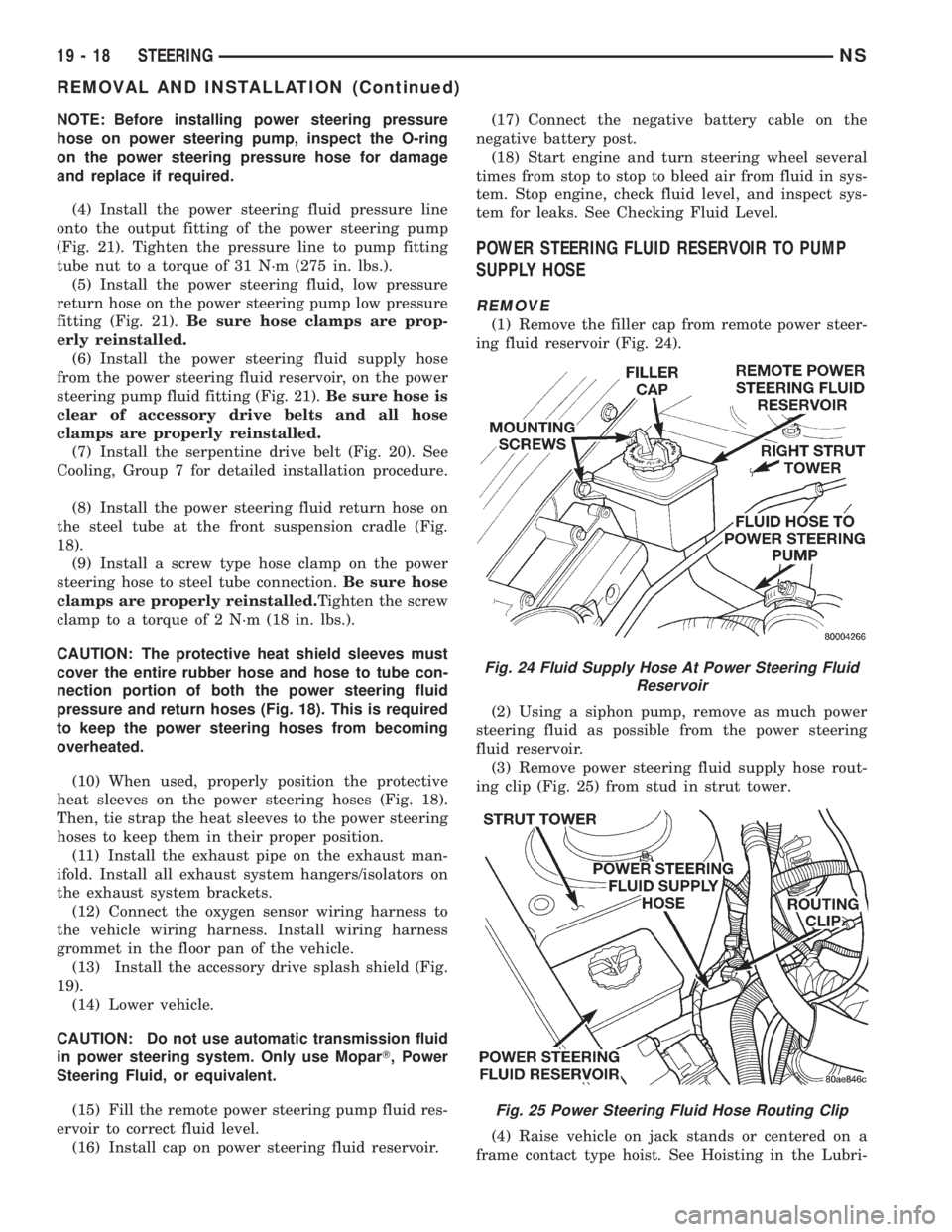
(8) Install the power steering fluid return hose on
the steel tube at the front suspension cradle (Fig.
18).
(9) Install a screw type hose clamp on the power
steering hose to steel tube connection.Be sure hose
clamps are properly reinstalled.Tighten the screw
clamp to a torque of 2 N´m (18 in. lbs.).
CAUTION: The protective heat shield sleeves must
cover the entire rubber hose and hose to tube con-
nection portion of both the power steering fluid
pressure and return hoses (Fig. 18). This is required
to keep the power steering hoses from becoming
overheated.
(10) When used, properly position the protective
heat sleeves on the power steering hoses (Fig. 18).
Then, tie strap the heat sleeves to the power steering
hoses to keep them in their proper position.
(11) Install the exhaust pipe on the exhaust man-
ifold. Install all exhaust system hangers/isolators on
the exhaust system brackets.
(12) Connect the oxygen sensor wiring harness to
the vehicle wiring harness. Install wiring harness
grommet in the floor pan of the vehicle.
(13) Install the accessory drive splash shield (Fig.
19).
(14) Lower vehicle.
CAUTION: Do not use automatic transmission fluid
in power steering system. Only use MoparT, Power
Steering Fluid, or equivalent.
(15) Fill the remote power steering pump fluid res-
ervoir to correct fluid level.
(16) Install cap on power steering fluid reservoir.(17) Connect the negative battery cable on the
negative battery post.
(18) Start engine and turn steering wheel several
times from stop to stop to bleed air from fluid in sys-
tem. Stop engine, check fluid level, and inspect sys-
tem for leaks. See Checking Fluid Level.
POWER STEERING FLUID RESERVOIR TO PUMP
SUPPLY HOSE
REMOVE
(1) Remove the filler cap from remote power steer-
ing fluid reservoir (Fig. 24).
(2) Using a siphon pump, remove as much power
steering fluid as possible from the power steering
fluid reservoir.
(3) Remove power steering fluid supply hose rout-
ing clip (Fig. 25) from stud in strut tower.
(4) Raise vehicle on jack stands or centered on a
frame contact type hoist. See Hoisting in the Lubri-
Fig. 24 Fluid Supply Hose At Power Steering Fluid
Reservoir
Fig. 25 Power Steering Fluid Hose Routing Clip
19 - 18 STEERINGNS
REMOVAL AND INSTALLATION (Continued)
Page 1445 of 1938
cation and Maintenance section of this service man-
ual, for the required lifting procedure to be used for
this vehicle.
(5) Remove at power steering pump, the power
steering fluid hose coming from the power steering
fluid reservoir. Let the power steering fluid drain out
of the reservoir and hose.
(6) Lower vehicle.
(7) Remove hose clamp attaching the power steer-
ing fluid supply hose to the power steering fluid res-
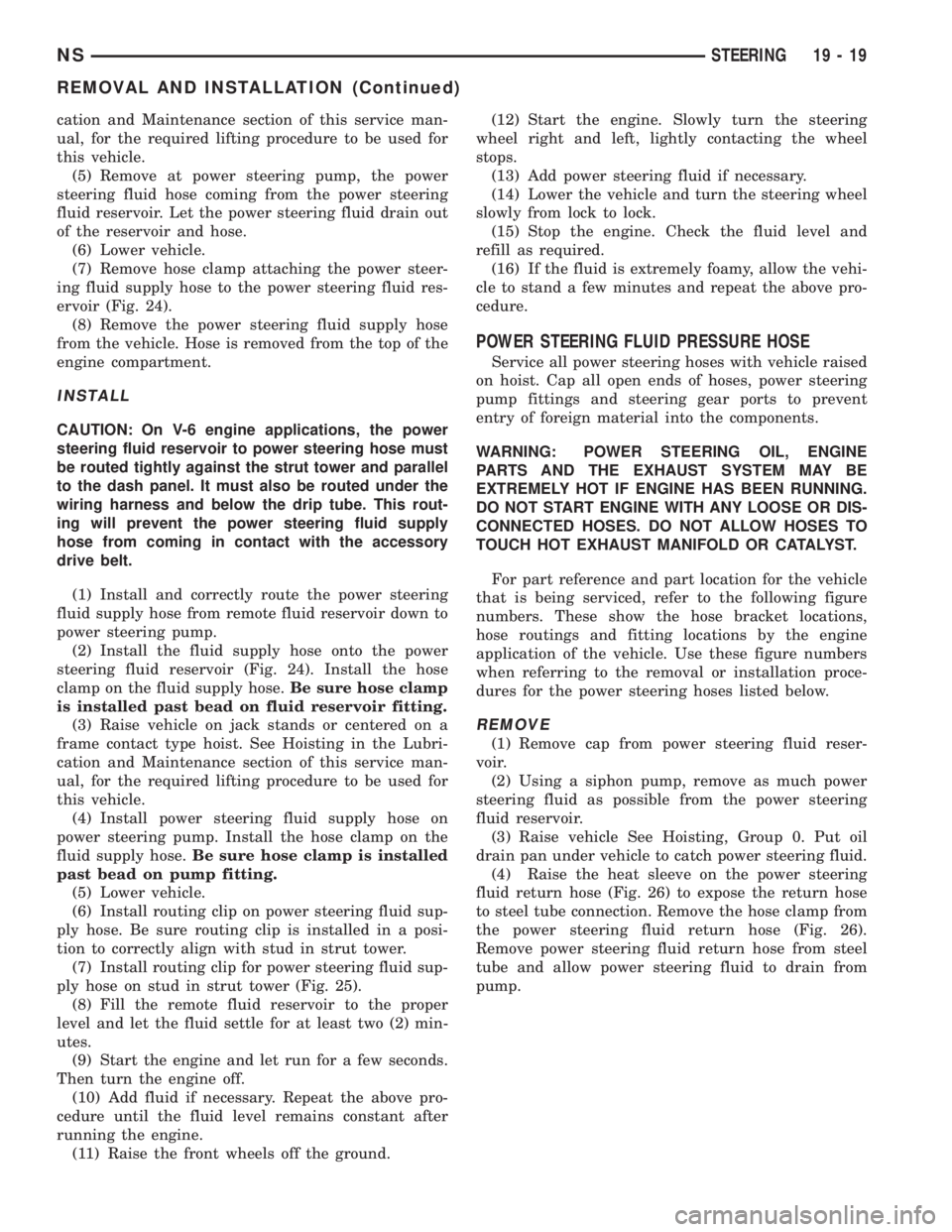
ervoir (Fig. 24).
(8) Remove the power steering fluid supply hose
from the vehicle. Hose is removed from the top of the
engine compartment.
INSTALL
CAUTION: On V-6 engine applications, the power
steering fluid reservoir to power steering hose must
be routed tightly against the strut tower and parallel
to the dash panel. It must also be routed under the
wiring harness and below the drip tube. This rout-
ing will prevent the power steering fluid supply
hose from coming in contact with the accessory
drive belt.
(1) Install and correctly route the power steering
fluid supply hose from remote fluid reservoir down to
power steering pump.
(2) Install the fluid supply hose onto the power
steering fluid reservoir (Fig. 24). Install the hose
clamp on the fluid supply hose.Be sure hose clamp
is installed past bead on fluid reservoir fitting.
(3) Raise vehicle on jack stands or centered on a
frame contact type hoist. See Hoisting in the Lubri-
cation and Maintenance section of this service man-
ual, for the required lifting procedure to be used for
this vehicle.
(4) Install power steering fluid supply hose on
power steering pump. Install the hose clamp on the
fluid supply hose.Be sure hose clamp is installed
past bead on pump fitting.
(5) Lower vehicle.
(6) Install routing clip on power steering fluid sup-
ply hose. Be sure routing clip is installed in a posi-
tion to correctly align with stud in strut tower.
(7) Install routing clip for power steering fluid sup-
ply hose on stud in strut tower (Fig. 25).
(8) Fill the remote fluid reservoir to the proper
level and let the fluid settle for at least two (2) min-
utes.
(9) Start the engine and let run for a few seconds.
Then turn the engine off.
(10) Add fluid if necessary. Repeat the above pro-
cedure until the fluid level remains constant after
running the engine.
(11) Raise the front wheels off the ground.(12) Start the engine. Slowly turn the steering
wheel right and left, lightly contacting the wheel
stops.
(13) Add power steering fluid if necessary.
(14) Lower the vehicle and turn the steering wheel
slowly from lock to lock.
(15) Stop the engine. Check the fluid level and
refill as required.
(16) If the fluid is extremely foamy, allow the vehi-
cle to stand a few minutes and repeat the above pro-
cedure.
POWER STEERING FLUID PRESSURE HOSE
Service all power steering hoses with vehicle raised
on hoist. Cap all open ends of hoses, power steering
pump fittings and steering gear ports to prevent
entry of foreign material into the components.
WARNING: POWER STEERING OIL, ENGINE
PARTS AND THE EXHAUST SYSTEM MAY BE
EXTREMELY HOT IF ENGINE HAS BEEN RUNNING.
DO NOT START ENGINE WITH ANY LOOSE OR DIS-
CONNECTED HOSES. DO NOT ALLOW HOSES TO
TOUCH HOT EXHAUST MANIFOLD OR CATALYST.
For part reference and part location for the vehicle
that is being serviced, refer to the following figure
numbers. These show the hose bracket locations,
hose routings and fitting locations by the engine
application of the vehicle. Use these figure numbers
when referring to the removal or installation proce-
dures for the power steering hoses listed below.
REMOVE
(1) Remove cap from power steering fluid reser-
voir.
(2) Using a siphon pump, remove as much power
steering fluid as possible from the power steering
fluid reservoir.
(3) Raise vehicle See Hoisting, Group 0. Put oil
drain pan under vehicle to catch power steering fluid.
(4) Raise the heat sleeve on the power steering
fluid return hose (Fig. 26) to expose the return hose
to steel tube connection. Remove the hose clamp from
the power steering fluid return hose (Fig. 26).
Remove power steering fluid return hose from steel
tube and allow power steering fluid to drain from
pump.
NSSTEERING 19 - 19
REMOVAL AND INSTALLATION (Continued)