cluster CHRYSLER VOYAGER 1996 Owner's Guide
[x] Cancel search | Manufacturer: CHRYSLER, Model Year: 1996, Model line: VOYAGER, Model: CHRYSLER VOYAGER 1996Pages: 1938, PDF Size: 55.84 MB
Page 369 of 1938
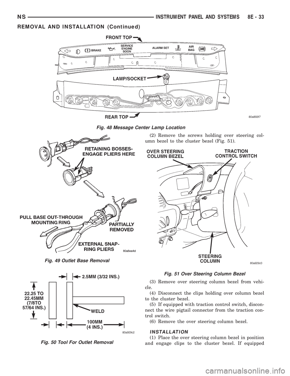
(2) Remove the screws holding over steering col-
umn bezel to the cluster bezel (Fig. 51).
(3) Remove over steering column bezel from vehi-
cle.
(4) Disconnect the clips holding over column bezel
to the cluster bezel.
(5) If equipped with traction control switch, discon-
nect the wire pigtail connector from the traction con-
trol switch.
(6) Remove the over steering column bezel.
INSTALLATION
(1) Place the over steering column bezel in position
and engage clips to the cluster bezel. If equipped
Fig. 48 Message Center Lamp Location
Fig. 49 Outlet Base Removal
Fig. 50 Tool For Outlet Removal
Fig. 51 Over Steering Column Bezel
NSINSTRUMENT PANEL AND SYSTEMS 8E - 33
REMOVAL AND INSTALLATION (Continued)
Page 370 of 1938
with traction control switch connect the wire pigtail
before engaging clips.
(2) Install the screws to hold the over steering col-
umn bezel to the cluster bezel.
(3) Install the lower column cover.
POWER MIRROR SWITCH
REMOVAL
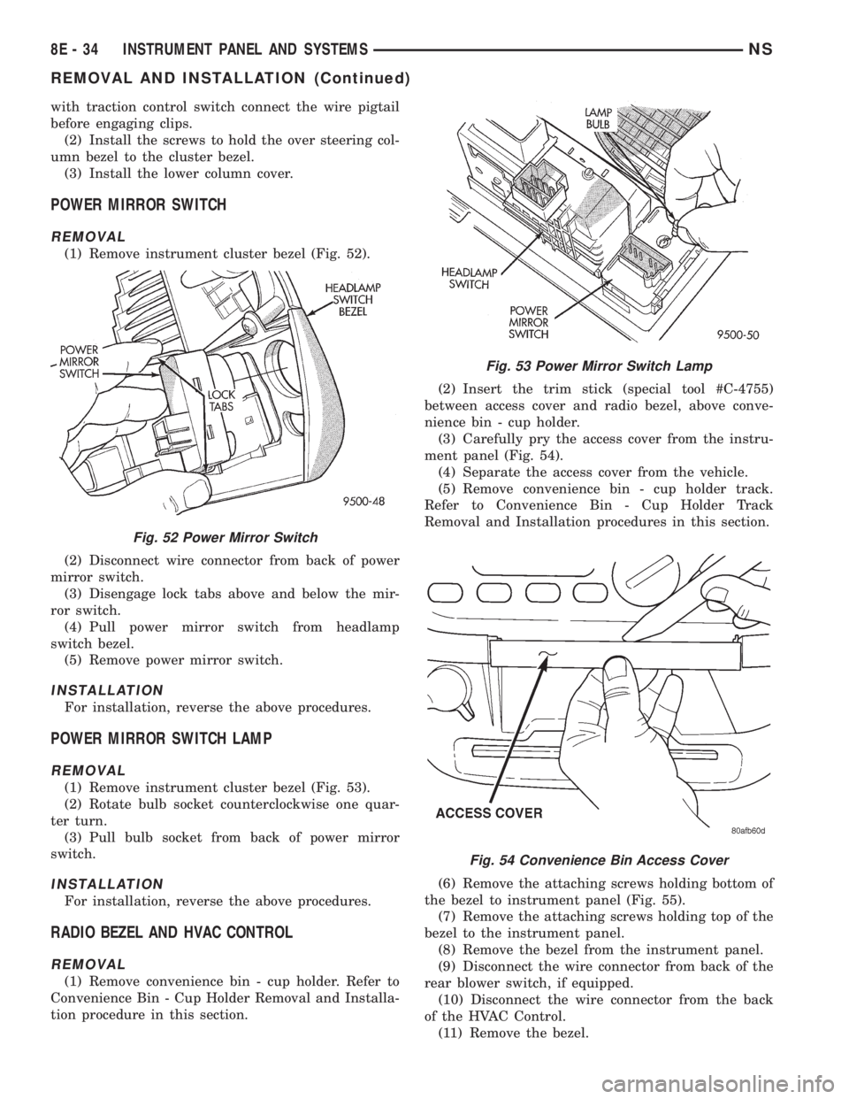
(1) Remove instrument cluster bezel (Fig. 52).
(2) Disconnect wire connector from back of power
mirror switch.
(3) Disengage lock tabs above and below the mir-
ror switch.
(4) Pull power mirror switch from headlamp
switch bezel.
(5) Remove power mirror switch.
INSTALLATION
For installation, reverse the above procedures.
POWER MIRROR SWITCH LAMP
REMOVAL
(1) Remove instrument cluster bezel (Fig. 53).
(2) Rotate bulb socket counterclockwise one quar-
ter turn.
(3) Pull bulb socket from back of power mirror
switch.
INSTALLATION
For installation, reverse the above procedures.
RADIO BEZEL AND HVAC CONTROL
REMOVAL
(1) Remove convenience bin - cup holder. Refer to
Convenience Bin - Cup Holder Removal and Installa-
tion procedure in this section.(2) Insert the trim stick (special tool #C-4755)
between access cover and radio bezel, above conve-
nience bin - cup holder.
(3) Carefully pry the access cover from the instru-
ment panel (Fig. 54).
(4) Separate the access cover from the vehicle.
(5) Remove convenience bin - cup holder track.
Refer to Convenience Bin - Cup Holder Track
Removal and Installation procedures in this section.
(6) Remove the attaching screws holding bottom of
the bezel to instrument panel (Fig. 55).
(7) Remove the attaching screws holding top of the
bezel to the instrument panel.
(8) Remove the bezel from the instrument panel.
(9) Disconnect the wire connector from back of the
rear blower switch, if equipped.
(10) Disconnect the wire connector from the back
of the HVAC Control.
(11) Remove the bezel.
Fig. 52 Power Mirror Switch
Fig. 53 Power Mirror Switch Lamp
Fig. 54 Convenience Bin Access Cover
8E - 34 INSTRUMENT PANEL AND SYSTEMSNS
REMOVAL AND INSTALLATION (Continued)
Page 373 of 1938
INSTRUMENT PANEL AND SYSTEMS
CONTENTS
page page
GENERAL INFORMATION
INTRODUCTION........................ 1
DESCRIPTION AND OPERATION
HEADLAMP AND POWER MIRROR
SWITCH LAMP(S)..................... 1
INSTRUMENT CLUSTER................. 2
DIAGNOSIS AND TESTING
DIAGNOSTIC PROCEDURES.............. 2
HEADLAMP SWITCH.................... 2
SELF DIAGNOSTIC TEST................. 3
REMOVAL AND INSTALLATION
ASH RECEIVER ± CONVENIENCE
BIN LAMP MODULE.................. 15
BODY CONTROL MODULE (BCM)......... 16
CIGAR LIGHTER BASE.................. 16
CONVENIENCE BIN.................... 15
CONVENIENCE BIN - CUP HOLDER....... 15
GLOVE BOX.......................... 17
GLOVE BOX LAMP AND SWITCH......... 17
GLOVE BOX LOCK STRIKER............. 17
HEADLAMP SWITCH................... 18
HEADLAMP SWITCH LAMP(S)........... 18
HVAC CONTROL LAMP................. 18
INSTRUMENT CLUSTER................ 20INSTRUMENT CLUSTER BACK PANEL..... 18
INSTRUMENT CLUSTER BEZEL.......... 18
INSTRUMENT CLUSTER LENS........... 19
INSTRUMENT CLUSTER PRINTED
CIRCUIT BOARD..................... 19
INSTRUMENT CLUSTER SUBDIAL........ 20
INSTRUMENT PANEL................... 20
INSTRUMENT PANEL LEFT END COVER.... 22
INSTRUMENT PANEL LOUVERS.......... 22
INSTRUMENT PANEL RIGHT END COVER . . 25
INSTRUMENT PANEL TOP COVER........ 24
JUNCTION BLOCK..................... 25
KNEE BLOCKER REINFORCEMENT........ 25
LOWER CONSOLE..................... 26
LOWER INSTRUMENT PANEL............ 26
LOWER STEERING COLUMN COVER...... 27
MESSAGE CENTER.................... 27
OVER STEERING COLUMN BEZEL........ 28
POWER MIRROR SWITCH.............. 28
POWER MIRROR SWITCH LAMP......... 28
RADIO BEZEL AND HVAC CONTROL....... 29
REAR HEATER-A/C SWITCH............. 29
REAR HEATER-A/C SWITCH LAMP........ 29
GENERAL INFORMATION
INTRODUCTION
The instrumentation gauges on GS vehicles are
contained in a subdial assemblies within the instru-
ment cluster. The individual gauges are not serviced
separately. If one of the cluster gauges becomes
faulty the entire subdial would require replacement
and all gauges will have to be calibrated. Refer to the
proper Body Diagnostic Procedure Manual for cali-
bration procedures.
DESCRIPTION AND OPERATION
HEADLAMP AND POWER MIRROR SWITCH
LAMP(S)
The Headlamp Switch and Power Mirror Switch
lamps are shown in (Fig. 1). For replacement of the
lamp(s) refer to Headlamp Switch Lamp(s) Removal
and Installation procedures below. Refer to Group 8T,
Power Mirrors for mirror test procedures.
NS/GSINSTRUMENT PANEL AND SYSTEMS 8E - 1
Page 374 of 1938
INSTRUMENT CLUSTER
The mechanical instrument cluster with a tachom-
eter is equipped with a electronic vacuum fluorescent
odometer, and trip odometer display.
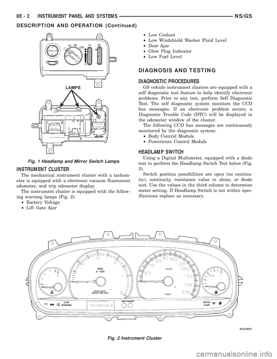
The instrument cluster is equipped with the follow-
ing warning lamps (Fig. 2).
²Battery Voltage
²Lift Gate Ajar²Low Coolant
²Low Windshield Washer Fluid Level
²Door Ajar
²Glow Plug Indicator
²Low Fuel Level
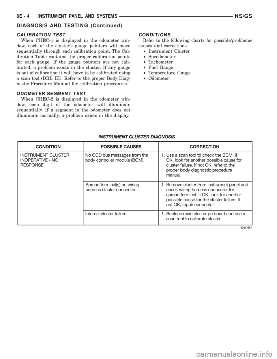
DIAGNOSIS AND TESTING
DIAGNOSTIC PROCEDURES
GS vehicle instrument clusters are equipped with a
self diagnostic test feature to help identify electronic
problems. Prior to any test, perform Self Diagnostic
Test. The self diagnostic system monitors the CCD
bus messages. If an electronic problem occurs, a
Diagnostic Trouble Code (DTC) will be displayed in
the odometer window of the cluster.
The following CCD bus messages are continuously
monitored by the diagnostic system:
²Body Control Module
²Powertrain Control Module
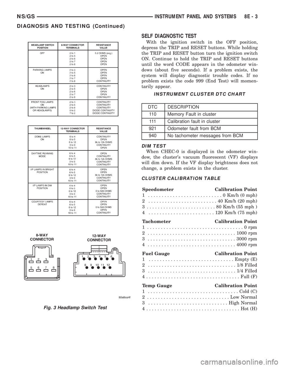
HEADLAMP SWITCH
Using a Digital Multimeter, equipped with a diode
test to perform the Headlamp Switch Test below (Fig.
3).
Switch position possibilities are open (no continu-
ity), continuity, resistance value in ohms, or diode
test. Use the values in the third column to determine
meter setting. If Headlamp Switch is not within spec-
ifications replace as necessary.
Fig. 2 Instrument Cluster
Fig. 1 Headlamp and Mirror Switch Lamps
8E - 2 INSTRUMENT PANEL AND SYSTEMSNS/GS
DESCRIPTION AND OPERATION (Continued)
Page 375 of 1938
SELF DIAGNOSTIC TEST
With the ignition switch in the OFF position,
depress the TRIP and RESET buttons. While holding
the TRIP and RESET button turn the ignition switch
ON. Continue to hold the TRIP and RESET buttons
until the word CODE appears in the odometer win-
dows (about five seconds). If a problem exists, the
system will display diagnostic trouble codes. If no
problem exists the code 999 (End Test) will momen-
tarily appear.
DIM TEST
When CHEC-0 is displayed in the odometer win-
dow, the cluster's vacuum fluorescent (VF) displays
will dim down. If the VF display brightness does not
change, a problem exists in the cluster.
CLUSTER CALIBRATION TABLE
Speedometer Calibration Point
1 ...........................0Km/h (0 mph)
2 .........................40Km/h (20 mph)
3 .........................80Km/h (55 mph )
4 ........................120Km/h (75 mph)
Tachometer Calibration Point
1 ...................................0rpm
2 ................................1000 rpm
3 ................................3000 rpm
4 ................................4000 rpm
Fuel Gauge Calibration Point
1 ...............................Empty (E)
2 ................................1/8Filled
3 ................................1/4Filled
4..................................Full (F)
Temp Gauge Calibration Point
1 .................................Cold (C)
2 ..............................LowNormal
3 .............................High Normal
4 ..................................Hot(H)
Fig. 3 Headlamp Switch Test
INSTRUMENT CLUSTER DTC CHART
DTC DESCRIPTION
110 Memory Fault in cluster
111 Calibration fault in cluster
921 Odometer fault from BCM
940 No tachometer messages from BCM
NS/GSINSTRUMENT PANEL AND SYSTEMS 8E - 3
DIAGNOSIS AND TESTING (Continued)
Page 376 of 1938
CALIBRATION TEST
When CHEC-1 is displayed in the odometer win-
dow, each of the cluster's gauge pointers will move
sequentially through each calibration point. The Cal-
ibration Table contains the proper calibration points
for each gauge. If the gauge pointers are not cali-
brated, a problem exists in the cluster. If any gauge
is out of calibration it will have to be calibrated using
a scan tool (DRB III). Refer to the proper Body Diag-
nostic Procedure Manual for calibration procedures.
ODOMETER SEGMENT TEST
When CHEC-2 is displayed in the odometer win-
dow, each digit of the odometer will illuminate
sequentially. If a segment in the odometer does not
illuminate normally, a problem exists in the display.
CONDITIONS
Refer to the following charts for possible/problems/
causes and corrections.
²Instrument Cluster
²Speedometer
²Tachometer
²Fuel Gauge
²Temperature Gauge
²Odometer
8E - 4 INSTRUMENT PANEL AND SYSTEMSNS/GS
DIAGNOSIS AND TESTING (Continued)
Page 390 of 1938
HEADLAMP SWITCH
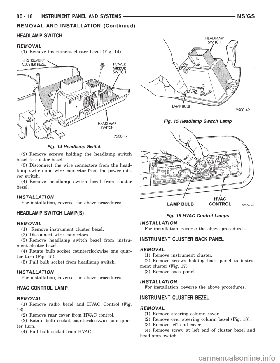
REMOVAL
(1) Remove instrument cluster bezel (Fig. 14).
(2) Remove screws holding the headlamp switch
bezel to cluster bezel.
(3) Disconnect the wire connectors from the head-
lamp switch and wire connector from the power mir-
ror switch.
(4) Remove headlamp switch bezel from cluster
bezel.
INSTALLATION
For installation, reverse the above procedures.
HEADLAMP SWITCH LAMP(S)
REMOVAL
(1) Remove instrument cluster bezel.
(2) Disconnect wire connectors.
(3) Remove headlamp switch bezel from instru-
ment cluster bezel.
(4) Rotate bulb socket counterclockwise one quar-
ter turn (Fig. 15).
(5) Pull bulb socket from headlamp switch.
INSTALLATION
For installation, reverse the above procedures.
HVAC CONTROL LAMP
REMOVAL
(1) Remove radio bezel and HVAC Control (Fig.
16).
(2) Remove rear cover from HVAC control.
(3) Rotate bulb socket counterclockwise one quar-
ter turn.
(4) Pull bulb socket from HVAC.
INSTALLATION
For installation, reverse the above procedures.
INSTRUMENT CLUSTER BACK PANEL
REMOVAL
(1) Remove instrument cluster.
(2) Remove screws holding back panel to instru-
ment cluster (Fig. 17).
(3) Remove back panel.
INSTALLATION
For installation, reverse the above procedures.
INSTRUMENT CLUSTER BEZEL
REMOVAL
(1) Remove steering column cover.
(2) Remove over steering column bezel (Fig. 18).
(3) Remove left end cover.
(4) Remove screw at left end of cluster bezel and
headlamp switch.
Fig. 14 Headlamp Switch
Fig. 15 Headlamp Switch Lamp
Fig. 16 HVAC Control Lamps
8E - 18 INSTRUMENT PANEL AND SYSTEMSNS/GS
REMOVAL AND INSTALLATION (Continued)
Page 391 of 1938
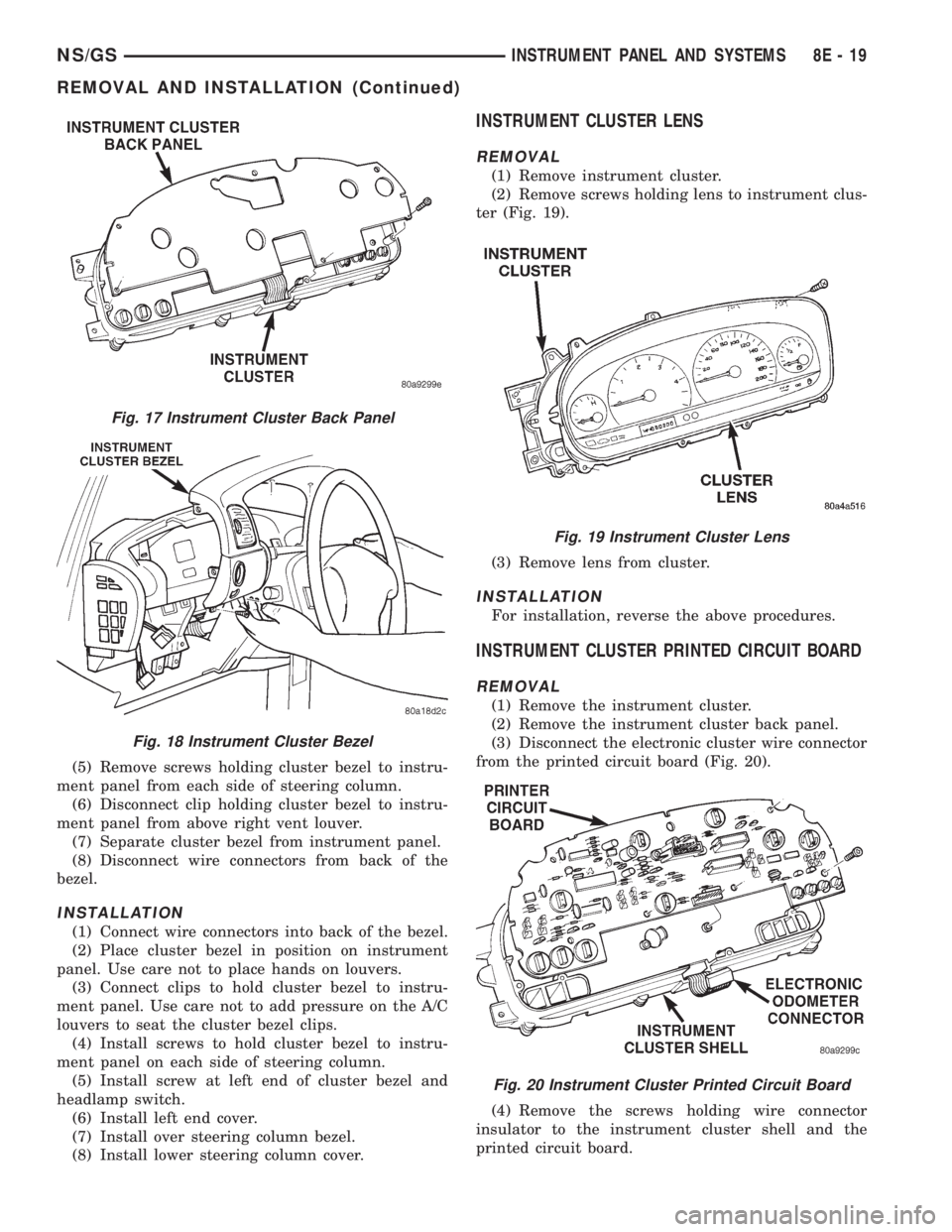
(5) Remove screws holding cluster bezel to instru-
ment panel from each side of steering column.
(6) Disconnect clip holding cluster bezel to instru-
ment panel from above right vent louver.
(7) Separate cluster bezel from instrument panel.
(8) Disconnect wire connectors from back of the
bezel.
INSTALLATION
(1) Connect wire connectors into back of the bezel.
(2) Place cluster bezel in position on instrument
panel. Use care not to place hands on louvers.
(3) Connect clips to hold cluster bezel to instru-
ment panel. Use care not to add pressure on the A/C
louvers to seat the cluster bezel clips.
(4) Install screws to hold cluster bezel to instru-
ment panel on each side of steering column.
(5) Install screw at left end of cluster bezel and
headlamp switch.
(6) Install left end cover.
(7) Install over steering column bezel.
(8) Install lower steering column cover.
INSTRUMENT CLUSTER LENS
REMOVAL
(1) Remove instrument cluster.
(2) Remove screws holding lens to instrument clus-
ter (Fig. 19).
(3) Remove lens from cluster.
INSTALLATION
For installation, reverse the above procedures.
INSTRUMENT CLUSTER PRINTED CIRCUIT BOARD
REMOVAL
(1) Remove the instrument cluster.
(2) Remove the instrument cluster back panel.
(3) Disconnect the electronic cluster wire connector
from the printed circuit board (Fig. 20).
(4) Remove the screws holding wire connector
insulator to the instrument cluster shell and the
printed circuit board.
Fig. 17 Instrument Cluster Back Panel
Fig. 18 Instrument Cluster Bezel
Fig. 19 Instrument Cluster Lens
Fig. 20 Instrument Cluster Printed Circuit Board
NS/GSINSTRUMENT PANEL AND SYSTEMS 8E - 19
REMOVAL AND INSTALLATION (Continued)
Page 392 of 1938
(5) Remove the screws holding printed circuit
board to the cluster shell.
(6) Remove the printed circuit board from the clus-
ter.
INSTALLATION
For installation, reverse the above procedures.
After installing the print circuit board it will have to
be calibrated using a scan tool (DRB III). Refer to the
proper Body Diagnostic Procedure Manual for cali-
bration procedures.
NOTE: Speedometer and/or Tachometer will not
operate properly until all gauges have been cali-
brated
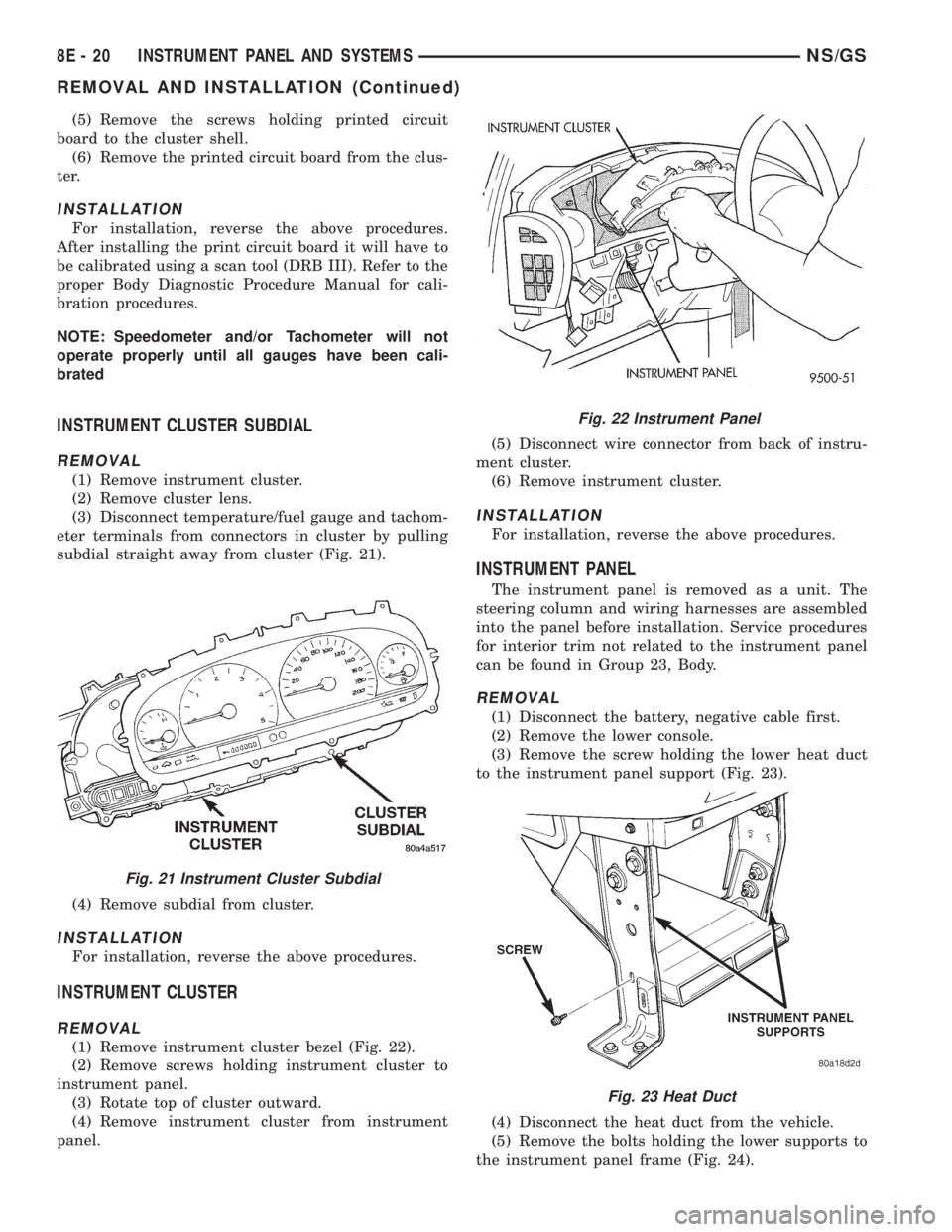
INSTRUMENT CLUSTER SUBDIAL
REMOVAL
(1) Remove instrument cluster.
(2) Remove cluster lens.
(3) Disconnect temperature/fuel gauge and tachom-
eter terminals from connectors in cluster by pulling
subdial straight away from cluster (Fig. 21).
(4) Remove subdial from cluster.
INSTALLATION
For installation, reverse the above procedures.
INSTRUMENT CLUSTER
REMOVAL
(1) Remove instrument cluster bezel (Fig. 22).
(2) Remove screws holding instrument cluster to
instrument panel.
(3) Rotate top of cluster outward.
(4) Remove instrument cluster from instrument
panel.(5) Disconnect wire connector from back of instru-
ment cluster.
(6) Remove instrument cluster.
INSTALLATION
For installation, reverse the above procedures.
INSTRUMENT PANEL
The instrument panel is removed as a unit. The
steering column and wiring harnesses are assembled
into the panel before installation. Service procedures
for interior trim not related to the instrument panel
can be found in Group 23, Body.
REMOVAL
(1) Disconnect the battery, negative cable first.
(2) Remove the lower console.
(3) Remove the screw holding the lower heat duct
to the instrument panel support (Fig. 23).
(4) Disconnect the heat duct from the vehicle.
(5) Remove the bolts holding the lower supports to
the instrument panel frame (Fig. 24).
Fig. 21 Instrument Cluster Subdial
Fig. 22 Instrument Panel
Fig. 23 Heat Duct
8E - 20 INSTRUMENT PANEL AND SYSTEMSNS/GS
REMOVAL AND INSTALLATION (Continued)
Page 394 of 1938
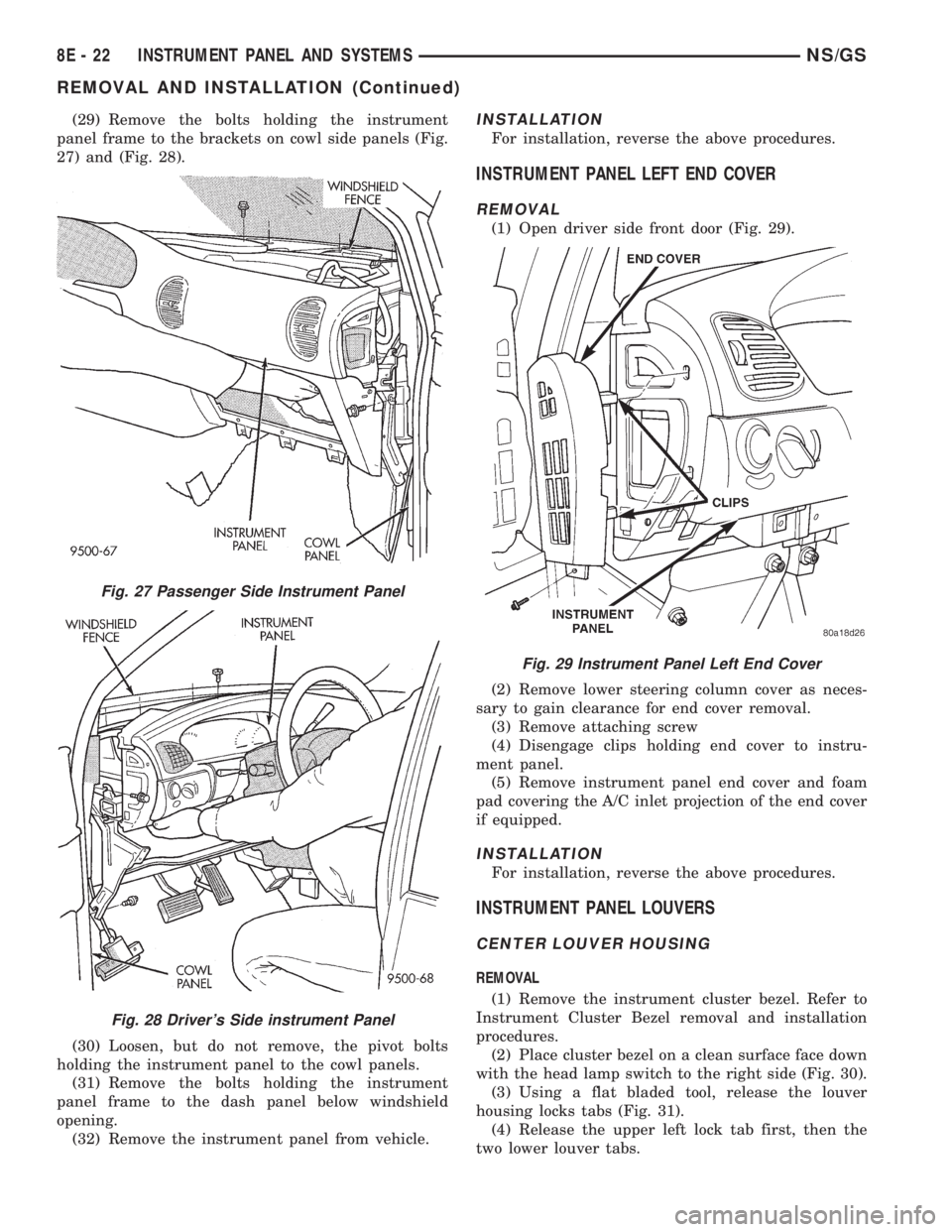
(29) Remove the bolts holding the instrument
panel frame to the brackets on cowl side panels (Fig.
27) and (Fig. 28).
(30) Loosen, but do not remove, the pivot bolts
holding the instrument panel to the cowl panels.
(31) Remove the bolts holding the instrument
panel frame to the dash panel below windshield
opening.
(32) Remove the instrument panel from vehicle.INSTALLATION
For installation, reverse the above procedures.
INSTRUMENT PANEL LEFT END COVER
REMOVAL
(1) Open driver side front door (Fig. 29).
(2) Remove lower steering column cover as neces-
sary to gain clearance for end cover removal.
(3) Remove attaching screw
(4) Disengage clips holding end cover to instru-
ment panel.
(5) Remove instrument panel end cover and foam
pad covering the A/C inlet projection of the end cover
if equipped.
INSTALLATION
For installation, reverse the above procedures.
INSTRUMENT PANEL LOUVERS
CENTER LOUVER HOUSING
REMOVAL
(1) Remove the instrument cluster bezel. Refer to
Instrument Cluster Bezel removal and installation
procedures.
(2) Place cluster bezel on a clean surface face down
with the head lamp switch to the right side (Fig. 30).
(3) Using a flat bladed tool, release the louver
housing locks tabs (Fig. 31).
(4) Release the upper left lock tab first, then the
two lower louver tabs.
Fig. 27 Passenger Side Instrument Panel
Fig. 28 Driver's Side instrument Panel
Fig. 29 Instrument Panel Left End Cover
8E - 22 INSTRUMENT PANEL AND SYSTEMSNS/GS
REMOVAL AND INSTALLATION (Continued)