cluster CHRYSLER VOYAGER 1996 Workshop Manual
[x] Cancel search | Manufacturer: CHRYSLER, Model Year: 1996, Model line: VOYAGER, Model: CHRYSLER VOYAGER 1996Pages: 1938, PDF Size: 55.84 MB
Page 395 of 1938
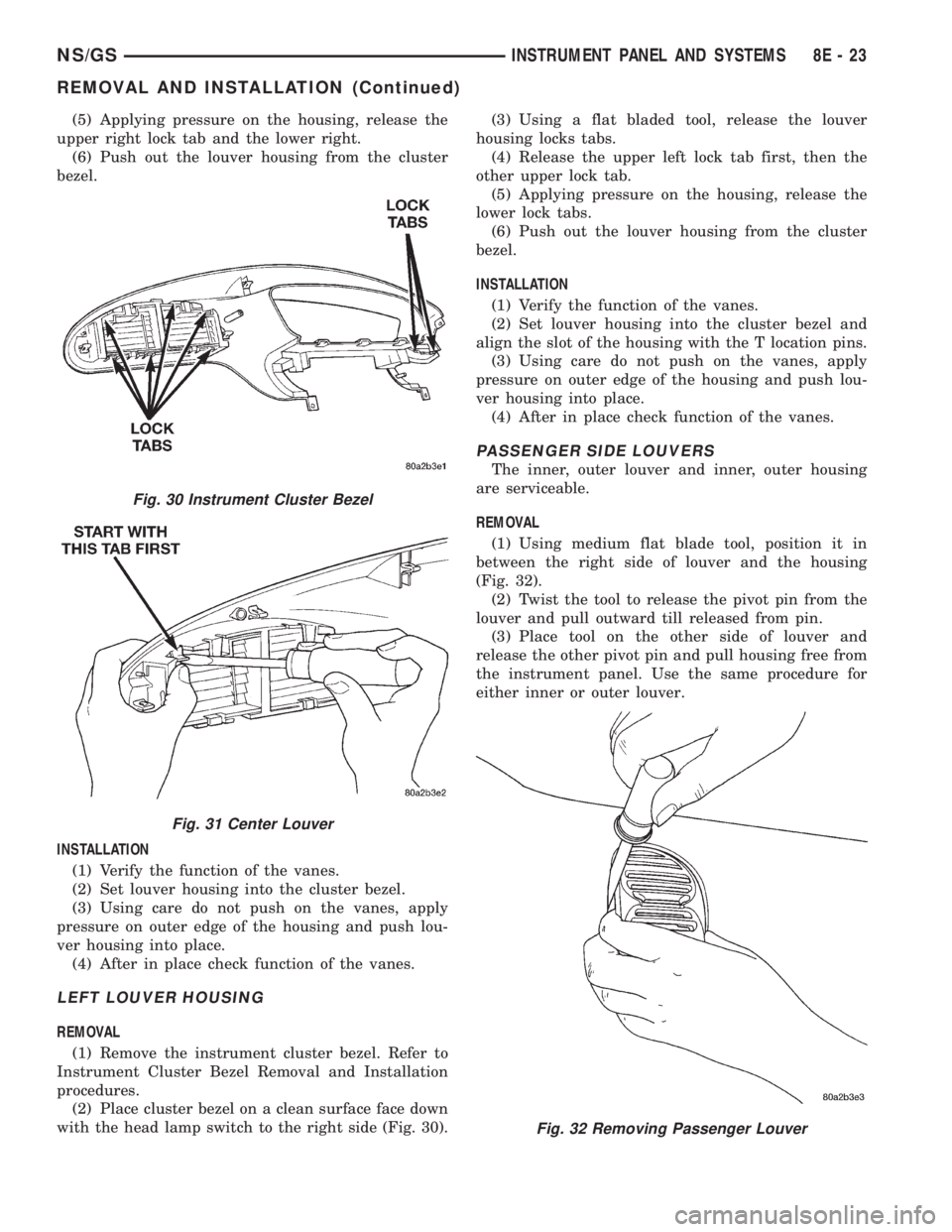
(5) Applying pressure on the housing, release the
upper right lock tab and the lower right.
(6) Push out the louver housing from the cluster
bezel.
INSTALLATION
(1) Verify the function of the vanes.
(2) Set louver housing into the cluster bezel.
(3) Using care do not push on the vanes, apply
pressure on outer edge of the housing and push lou-
ver housing into place.
(4) After in place check function of the vanes.
LEFT LOUVER HOUSING
REMOVAL
(1) Remove the instrument cluster bezel. Refer to
Instrument Cluster Bezel Removal and Installation
procedures.
(2) Place cluster bezel on a clean surface face down
with the head lamp switch to the right side (Fig. 30).(3) Using a flat bladed tool, release the louver
housing locks tabs.
(4) Release the upper left lock tab first, then the
other upper lock tab.
(5) Applying pressure on the housing, release the
lower lock tabs.
(6) Push out the louver housing from the cluster
bezel.
INSTALLATION
(1) Verify the function of the vanes.
(2) Set louver housing into the cluster bezel and
align the slot of the housing with the T location pins.
(3) Using care do not push on the vanes, apply
pressure on outer edge of the housing and push lou-
ver housing into place.
(4) After in place check function of the vanes.
PASSENGER SIDE LOUVERS
The inner, outer louver and inner, outer housing
are serviceable.
REMOVAL
(1) Using medium flat blade tool, position it in
between the right side of louver and the housing
(Fig. 32).
(2) Twist the tool to release the pivot pin from the
louver and pull outward till released from pin.
(3) Place tool on the other side of louver and
release the other pivot pin and pull housing free from
the instrument panel. Use the same procedure for
either inner or outer louver.
Fig. 30 Instrument Cluster Bezel
Fig. 31 Center Louver
Fig. 32 Removing Passenger Louver
NS/GSINSTRUMENT PANEL AND SYSTEMS 8E - 23
REMOVAL AND INSTALLATION (Continued)
Page 399 of 1938
(11) Remove screw holding lower instrument panel
to right side of instrument panel.
(12) Remove screw holding lower instrument panel
to upper instrument panel at left side panel above
accelerator pedal.
(13) Remove instrument cluster bezel as necessary
to gain access to lower instrument panel screws.
(14) Remove screw lower holding instrument panel
to upper panel below instrument cluster.
(15) Remove screws holding rear of storage pocket
to panel support frame.
(16) Remove screws holding lower instrument
panel to upper instrument panel from below radio.
(17) Remove screws holding lower instrument
panel to support frame in floor console area.
(18) Separate lower instrument from upper instru-
ment panel.
(19) Disengage wire connectors from back of acces-
sory plug.
(20) Separate lower instrument from vehicle.
INSTALLATION
For installation, reverse the above procedures.
LOWER STEERING COLUMN COVER
REMOVAL
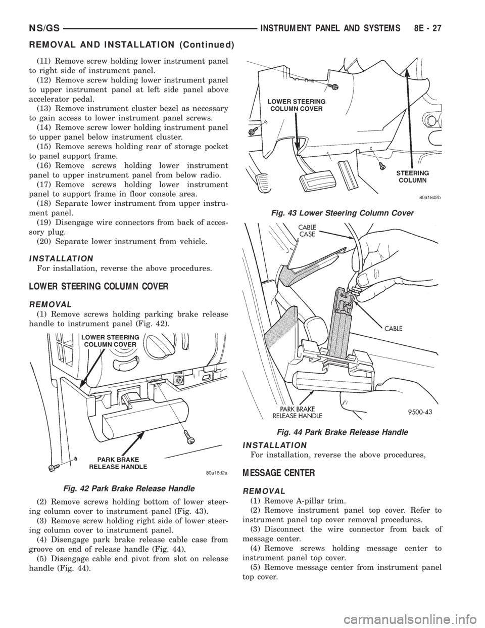
(1) Remove screws holding parking brake release
handle to instrument panel (Fig. 42).
(2) Remove screws holding bottom of lower steer-
ing column cover to instrument panel (Fig. 43).
(3) Remove screw holding right side of lower steer-
ing column cover to instrument panel.
(4) Disengage park brake release cable case from
groove on end of release handle (Fig. 44).
(5) Disengage cable end pivot from slot on release
handle (Fig. 44).
INSTALLATION
For installation, reverse the above procedures,
MESSAGE CENTER
REMOVAL
(1) Remove A-pillar trim.
(2) Remove instrument panel top cover. Refer to
instrument panel top cover removal procedures.
(3) Disconnect the wire connector from back of
message center.
(4) Remove screws holding message center to
instrument panel top cover.
(5) Remove message center from instrument panel
top cover.
Fig. 42 Park Brake Release Handle
Fig. 43 Lower Steering Column Cover
Fig. 44 Park Brake Release Handle
NS/GSINSTRUMENT PANEL AND SYSTEMS 8E - 27
REMOVAL AND INSTALLATION (Continued)
Page 400 of 1938
INSTALLATION
(1) Place message center in position on top cover.
(2) Install screws to hold message center to instru-
ment panel top cover.
(3) Connect wire connector into back of message
center.
(4) Install instrument panel top cover.
(5) Install A-pillar trim.
OVER STEERING COLUMN BEZEL
REMOVAL
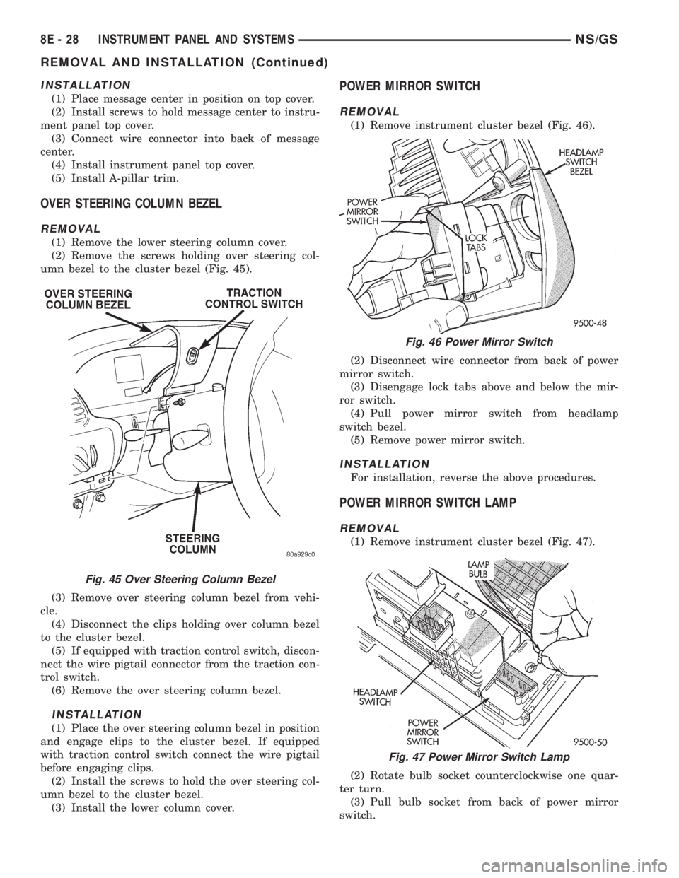
(1) Remove the lower steering column cover.
(2) Remove the screws holding over steering col-
umn bezel to the cluster bezel (Fig. 45).
(3) Remove over steering column bezel from vehi-
cle.
(4) Disconnect the clips holding over column bezel
to the cluster bezel.
(5) If equipped with traction control switch, discon-
nect the wire pigtail connector from the traction con-
trol switch.
(6) Remove the over steering column bezel.
INSTALLATION
(1) Place the over steering column bezel in position
and engage clips to the cluster bezel. If equipped
with traction control switch connect the wire pigtail
before engaging clips.
(2) Install the screws to hold the over steering col-
umn bezel to the cluster bezel.
(3) Install the lower column cover.
POWER MIRROR SWITCH
REMOVAL
(1) Remove instrument cluster bezel (Fig. 46).
(2) Disconnect wire connector from back of power
mirror switch.
(3) Disengage lock tabs above and below the mir-
ror switch.
(4) Pull power mirror switch from headlamp
switch bezel.
(5) Remove power mirror switch.
INSTALLATION
For installation, reverse the above procedures.
POWER MIRROR SWITCH LAMP
REMOVAL
(1) Remove instrument cluster bezel (Fig. 47).
(2) Rotate bulb socket counterclockwise one quar-
ter turn.
(3) Pull bulb socket from back of power mirror
switch.
Fig. 45 Over Steering Column Bezel
Fig. 46 Power Mirror Switch
Fig. 47 Power Mirror Switch Lamp
8E - 28 INSTRUMENT PANEL AND SYSTEMSNS/GS
REMOVAL AND INSTALLATION (Continued)
Page 403 of 1938

AUDIO SYSTEMS
CONTENTS
page page
GENERAL INFORMATION
INTRODUCTION......................... 1
DESCRIPTION AND OPERATION
ANTENNA.............................. 1
CHOKEÐINFINITY SPEAKERS.............. 2
INTERFERENCE ELIMINATION.............. 1
NAME BRAND SPEAKER RELAY............ 3
RADIO IGNITION INTERFERENCE........... 2
RADIOS................................ 1
REMOTE RADIO SWITCHES................ 3
DIAGNOSIS AND TESTING
ANTENNA.............................. 3AUDIO SYSTEM......................... 4
RADIO................................. 4
REMOTE RADIO SWITCHES................ 6
REMOVAL AND INSTALLATION
ANTENNA EXTENSION CABLE.............. 7
ANTENNA MAST AND CABLE LEAD......... 7
D±PILLAR SPEAKER.................... 10
FRONT DOOR SPEAKER................... 9
INSTRUMENT PANEL SPEAKER............. 8
QUARTER PANEL SPEAKER............... 10
RADIO/TAPE/CD PLAYER.................. 8
REMOTE RADIO SWITCHES................ 9
GENERAL INFORMATION
INTRODUCTION
Operating instructions for the factory installed
audio systems can be found in the Owner's Manual
provided with the vehicle.
NS vehicles are equipped with an Ignition Off
Draw (IOD) fuse in the power distribution center
located in the engine compartment. After the IOD
fuse or battery has been disconnected, the radio sta-
tion sets and clock will require resetting.
DESCRIPTION AND OPERATION
ANTENNA
All models use a fixed-length stainless steel rod-
type antenna mast, installed at the right front fender
of the vehicle. The antenna mast is connected to the
center wire of the coaxial antenna cable, and is not
grounded to any part of the vehicle.
To eliminate static, the antenna base must have a
good ground. The coaxial antenna cable shield (the
outer wire mesh of the cable) is grounded to the
antenna base and the radio chassis.
The antenna coaxial cable has an additional dis-
connect, located near the right end of the instrument
panel. This additional disconnect allows the instru-
ment panel assembly to be removed and installed
without removing the radio.
The factory-installed Electronically Tuned Radios
(ETRs) automatically compensate for radio antenna
trim. Therefore, no antenna trimmer adjustment isrequired or possible when replacing the receiver or
the antenna.
INTERFERENCE ELIMINATION
Some components used on the vehicles are
equipped with a capacitor to suppress radio fre-
quency interference/static.
Capacitors are mounted in various locations inter-
nal to the generator, instrument cluster and wind-
shield wiper motor.
To eliminate radio interference, ground straps are
used in different areas of the vehicle. These ground
circuits should be securely tightened to assure good
metal to metal contact. The ground straps conduct
very small high frequency electrical signals to ground
and require clean surface contact area. The radio
ground is supplied from the instrument panel har-
ness and is attached to the rear of the radio. Some
engines have other ground straps to eliminate fur-
ther radio interference:
²Radio chassis to instrument panel structure
²Engine to dash panel
²Engine to chassis
²A/C h valve to dash panel
Radio resistance type spark plug cables in the high
tension circuit of the ignition system complete the
interference suppression. Faulty or deteriorated
spark plug wires should be replaced.
RADIOS
Available factory-installed radio receivers for this
model include an AM/FM/cassette (RAS sales code),
an AM/FM/cassette/5-band graphic equalizer with CD
changer control feature (RBN sales code), an AM/FM/
NSAUDIO SYSTEMS 8F - 1
Page 408 of 1938
(1) Check the fuse(s) in the junction block and the
Power Distribution Center (PDC). If OK, go to Step
2. If not OK, repair the shorted circuit or component
as required and replace the faulty fuse(s).
(2) Check for battery voltage at the fuse in the
PDC. If OK, go to Step 3. If not OK, repair the open
circuit to the battery as required.
(3) Turn the ignition switch to the ON position.
Check for battery voltage at the fuse in the junction
block. If OK, go to Step 4. If not OK, repair the open
circuit to the ignition switch as required.
(4) Turn the ignition switch to the OFF position.
Disconnect and isolate the battery negative cable.
Remove the instrument cluster center bezel. Remove
the radio, but do not unplug the wire harness connec-
tors. Check for continuity between the radio chassis
and a good ground. There should be continuity. If
OK, go to Step 5. If not OK, repair the open radio
chassis ground circuit as required.
(5) Connect the battery negative cable. Turn the
ignition switch to the ON position. Check for battery
voltage at the fused ignition switch output circuit
cavity of the left (gray) radio wire harness connector.
If OK, go to Step 6. If not OK, repair the open circuit
as required.
(6) Turn the ignition switch to the OFF position.
Check for battery voltage at the fused B(+) circuit
cavity of the left (gray) radio wire harness connector.
If OK, replace the faulty radio. If not OK, repair the
open circuit to the Ignition-Off Draw (IOD) fuse as
required.
REMOTE RADIO SWITCHES
WARNING: ON VEHICLES EQUIPPED WITH AIR-
BAGS, REFER TO GROUP 8M - PASSIVE
RESTRAINT SYSTEMS BEFORE ATTEMPTING ANY
STEERING WHEEL, STEERING COLUMN, OR
INSTRUMENT PANEL COMPONENT DIAGNOSIS OR
SERVICE. FAILURE TO TAKE THE PROPER PRE-
CAUTIONS COULD RESULT IN ACCIDENTAL AIR-
BAG DEPLOYMENT AND POSSIBLE PERSONAL
INJURY.
(1) Disconnect and isolate the battery negative
cable. Wait two minutes for the airbag system capac-
itor to discharge before further service.
(2) Remove the remote radio switch(es) from the
steering wheel.
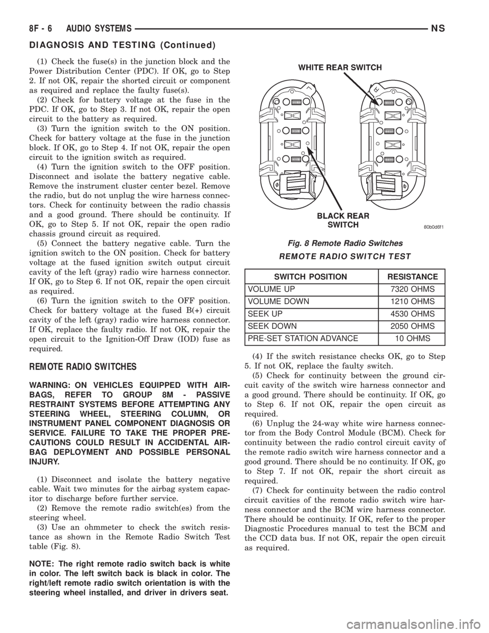
(3) Use an ohmmeter to check the switch resis-
tance as shown in the Remote Radio Switch Test
table (Fig. 8).
NOTE: The right remote radio switch back is white
in color. The left switch back is black in color. The
right/left remote radio switch orientation is with the
steering wheel installed, and driver in drivers seat.(4) If the switch resistance checks OK, go to Step
5. If not OK, replace the faulty switch.
(5) Check for continuity between the ground cir-
cuit cavity of the switch wire harness connector and
a good ground. There should be continuity. If OK, go
to Step 6. If not OK, repair the open circuit as
required.
(6) Unplug the 24-way white wire harness connec-
tor from the Body Control Module (BCM). Check for
continuity between the radio control circuit cavity of
the remote radio switch wire harness connector and a
good ground. There should be no continuity. If OK, go
to Step 7. If not OK, repair the short circuit as
required.
(7) Check for continuity between the radio control
circuit cavities of the remote radio switch wire har-
ness connector and the BCM wire harness connector.
There should be continuity. If OK, refer to the proper
Diagnostic Procedures manual to test the BCM and
the CCD data bus. If not OK, repair the open circuit
as required.
Fig. 8 Remote Radio Switches
REMOTE RADIO SWITCH TEST
SWITCH POSITION RESISTANCE
VOLUME UP 7320 OHMS
VOLUME DOWN 1210 OHMS
SEEK UP 4530 OHMS
SEEK DOWN 2050 OHMS
PRE-SET STATION ADVANCE 10 OHMS
8F - 6 AUDIO SYSTEMSNS
DIAGNOSIS AND TESTING (Continued)
Page 427 of 1938
VEHICLE SPEED CONTROL SYSTEM
CONTENTS
page
GENERAL INFORMATION
INTRODUCTION........................ 1
GENERAL INFORMATION
INTRODUCTION
This group covers both Left-Hand Drive (LHD) and
Right-Hand Drive (RHD) versions of this model.
Whenever feasible, the RHD versions of affected
vehicle components have been constructed as mirror-
image of the LHD versions. While most of the illus-
trations used in this group represent only the LHD
version, the diagnostic and service procedures out-
lined can generally be applied to either version.
Exceptions to this rule have been clearly identified as
LHD or RHD, if a special illustration or procedure
was/is required.
The speed control system used with the 2.5L diesel
engine is basically identical to the system used with
gasoline powered engines. Features unique to the
diesel engine will be covered in this section.
²Models equipped with the 2.5L diesel engine do
not use a vacuum reservoir to retain engine vacuum
for speed control operation. There are no vaccum-op-
erated speed control servos used in vehicles with the
2.5L diesel engine.
²The range of the speed control system operation
is restricted to speeds between 56 km/h (35 MPH) to
145 km/h (90 MPH).
²Inputs to the MSA that allow speed control oper-
ation are from the vehicle speed sensor and the
Speed Control Switch.²Two separate speed control switch modules are
mounted on the steering wheel to the left and right
side of the driver's airbag module. Switch features
are:
a. Within the two switch modules, fivemomen-
tarycontact switches, supporting seven different
speed control functions are used.
b. The outputs from these switches are filtered
into one input. The MSA determines which output
has been applied throughresistive multiplexing.
The input circuit voltage is measured by the MSA
to determine which switch function has been
selected.
c. A speed control indicator lamp, located on the
instrument panel cluster is energized by the MSA
via the CCD Bus. This occurs when speed control
system power has been turned ON, and the engine
is running.
d. The two switch modules are labeled: ON/OFF,
SET, RESUME/ACCEL, CANCEL and COAST.
Refer to the owner's manual for more information
on speed control switch functions and setting pro-
cedures. The individual switches cannot be
repaired. If one individual switch fails, the switch
module must be replaced.
NS/GSVEHICLE SPEED CONTROL SYSTEM 8H - 1
Page 429 of 1938

TURN SIGNAL AND FLASHERS
CONTENTS
page page
GENERAL INFORMATION
COMBINATION FLASHER.................. 1
INTRODUCTION......................... 1
DESCRIPTION AND OPERATION
COMBINATION FLASHER / DAYTIME
RUNNING LAMPS (DRL) MODULE......... 2
COMBINATION FLASHER FUNCTION......... 1DIAGNOSIS AND TESTING
COMBINATION FLASHER WITH / WITHOUT
DAYTIME RUNNING LAMPS MODULEÐ
CIRCUIT DIAGNOSTICS.................. 3
TURN SIGNAL MULTI-FUNCTION SWITCH.... 2
REMOVAL AND INSTALLATION
COMBINATION FLASHER WITH / WITHOUT
DRL MODULE........................ 11
MULTI-FUNCTION SWITCH............... 11
GENERAL INFORMATION
INTRODUCTION
The turn signals are actuated with a lever on the
left side of the steering column just ahead of the
steering wheel. The signals are automatically turned
off by a canceling cam (two lobes molded to the clock-
spring mechanism). The cam comes in contact with
the cancel actuator on the turn signal (multi-func-
tion) switch assembly. Either cam lobe, pushing on
the cancel actuator, returns the switch to the OFF
position.
Lane change signaling is actuated by applying par-
tial turn signal stalk movement toward the direction
desired until the indicator lamps flashes in the
instrument cluster. When the switch stalk is released
the stalk will spring back into the neutral position
turning OFF the turn signal.
With the ignition switch ON and the turn signal
switch stalk actuated left or right, current flows
through the:
²Combination flasher
²Multi-function switch
²Turn indicator lamp
²Front and rear turn signal bulbs.
A chime will sound after the vehicle has traveled a
distance of approximately 0.5 mile with the turn sig-
nal ON.
COMBINATION FLASHER
The Turn Signal/Hazard Warning Flasher is a
module providing the vehicle with turn signal and
hazard warning functions and has been designed
with internal relays to take advantage of low current
switching requirements in the vehicle. It is plugged
into the Junction Block at position 4 (Fig. 1), where
all wiring associated with its operation is terminated.The Junction Block is adjacent to and left of the
steering column of the vehicle.
To gain access to the flasher, remove the lower
steering column cover and knee blocker. Refer to
Group 8E, Instrument Panel and Systems for
removal procedures.
DESCRIPTION AND OPERATION
COMBINATION FLASHER FUNCTION
The Turn Signal/Hazard Warning Flasher is a
module providing turn signal, hazard warning func-
tions and has been designed with internal relays to
Fig. 1 Combination Flasher Location
NSTURN SIGNAL AND FLASHERS 8J - 1
Page 477 of 1938
BULB APPLICATION
INDEX
page page
GENERAL INFORMATION
INTRODUCTION......................... 25SPECIFICATIONS
EXTERIOR LAMP BULBS.................. 25
INTERIOR LAMP BULBS.................. 25
GENERAL INFORMATION
INTRODUCTION
The following Bulb Application Tables list the lamp
title on the left side of the column and trade number
or part number on the right.
CAUTION: Do not use bulbs that have a higher
candle power than the bulb listed in the Bulb Appli-
cation Table. Damage to lamp can result.
Do not touch halogen bulbs with fingers or other
possibly oily surfaces. Bulb life will be reduced.
If a halogen bulb is contaminated with oil, clean
bulb with denatured alcohol or ammonia based sol-
vent.
SPECIFICATIONS
EXTERIOR LAMP BULBS
LAMP BULB
Back-up...............................3057
CHMSL................................921
Fog Lamp...............................H3
FogLamp±T&C ........................9040
Headlamp..............................9007
Headlamp high beam ± T&C...............9005
Headlamp low beam ± T&C............9005 SLL
License Plate............................168
Parking/Turn Signal/Front Side Marker. . . .3157NA
Parking/Turn Signal ± T&C............4157NAK
Tail, Stop, Turn Signal and Side Marker......3057
Front Side Marker......................194NA
INTERIOR LAMP BULBS
LAMP BULB
ABS.................................PC194
AirBag ..............................PC194
Alarm Set (Security)....................PC194
Brake Warning.........................PC194
Center/Rear Reading Lamps.................578
Center/Rear Dome Lamps...................579
Check Engine Ind.......................PC194
Front Door Courtesy.......................567
Door Ajar Ind..........................PC194
Front Header Reading Lamp................567
Glove Box Lamp..........................194
High Beam Ind.........................PC194
Instrument Cluster.....................PC194
IP Bin/Ash Tray..........................161
Liftgate Flood Lamps......................567
Liftgate Ajar Ind.........................PC74
Low Fuel Ind..........................PC194
Oil Pressure Ind........................PC194
O/H Console Reading Lamps................579
Seat Belt Ind...........................PC74
Engine Temp Ind.......................PC194
Turn Signal...........................PC194
Engine Compartment Lamps................579
Visor Vanity Lamp....................6501966
Low Washer Fluid.......................PC74
Low Volts Warning.......................PC74
Cruise Indicator........................PC194
NSLAMPS 8L - 25
Page 495 of 1938
BULB APPLICATION
INDEX
page page
GENERAL INFORMATION
INTRODUCTION....................... 17
CLEANING AND INSPECTION
HEADLAMP CLEANING.................. 17SPECIFICATIONS
EXTERIOR LAMP BULBS................. 17
INTERIOR LAMP BULBS................. 17
GENERAL INFORMATION
INTRODUCTION
The following Bulb Application Tables list the lamp
title on the left side of the column and trade number
or part number on the right.
CAUTION: Do not use bulbs that have a higher
candle power than the bulb listed in the Bulb Appli-
cation Table. Damage to lamp can result.
Do not touch halogen bulbs with fingers or other
possibly oily surfaces. Bulb life will be reduced.
If a halogen bulb is contaminated with oil, clean
bulb with denatured alcohol or ammonia based sol-
vent.
CLEANING AND INSPECTION
HEADLAMP CLEANING
This vehicle is equipped with plastic headlights
that are lighter and less susceptible to stone break-
age than glass headlights.
This plastic is not as scratch resistant as glass and
therefore a different lens cleaning procedures must
be followed.
To minimize the possibility of scratching the lenses
and reducing light output, avoid wiping with a dry
cloth. To remove road dirt, wash with a mild soap
solution followed by rinsing with water.
Do not use abrasive cleaning components, solvents,
steel wool or other aggressive material to clean the
lenses.
SPECIFICATIONS
EXTERIOR LAMP BULBS
LAMP BULB
Back-up.............................P21W
CHMSL (Non-Solar Tint)................P21W
CHMSL (Solar Tint)....................R10WLAMP BULB
Fog Lamp..............................H3
Headlamp..............................H4
License Plate..........................C5W
Front Turn Signal....................PY21W
Citylight..............................T4W
Front Side Repeater.....................T4W
Tail, Stop...........................P21/5W
Rear Turn Signal......................P21W
Rear Fog Lamp........................P21W
INTERIOR LAMP BULBS
LAMP BULB
ABS ................................PC194
AirBag .............................PC194
Alarm Set (Security/Immobilzer)..........PC194
Brake Warning.......................PC194
Center/Rear Reading Lamps...............578
Center/Rear Dome Lamps.................579
Cruise Indicator.......................PC194
Door Ajar Indicator....................PC194
Engine Compartment Lamps...............579
Engine Temp Indicator.................PC194
Front Door Courtesy......................567
Glove Box Lamp.........................194
Glow Plug Indicator (Diesel Engine Only) . . . PC194
High Beam Indicator...................PC194
Instrument Cluster....................PC194
IP/Ash Tray (Left Hand Drive Only).........161
Liftgate Flood Lamps.....................567
Liftgate Ajar Indicator...................PC74
Low Coolant Level (Diesel Engine Only).....PC74
Low Fuel Indicator....................PC194
Low Volts Warning.....................PC74
Low Washer Fluid......................PC74
Oil Pressure Indicator..................PC194
O/H Console Reading Lamps...............579
Seat Belt Indicator (Except Diesel).........PC74
Service Engine Soon...................PC194
Turn Signal..........................PC194
Visor Vanity Lamp...................6501966
NS/GSLAMPS 8L - 17
Page 519 of 1938
VEHICLE THEFT/SECURITY SYSTEMS
CONTENTS
page page
GENERAL INFORMATION
INTRODUCTION........................ 1
SMART KEY IMMOBILIZER SYSTEM....... 1
DESCRIPTION AND OPERATION
SMART KEY IMMOBILIZER MODULE....... 1
SMART KEY IMMOBILIZER SYSTEM
INDICATOR LAMP..................... 3
SMART KEY IMMOBILIZER TRANSPONDER . 2DIAGNOSIS AND TESTING
SMART KEY IMMOBILIZER SYSTEM....... 3
SERVICE PROCEDURES
SMART KEY IMMOBILIZER SYSTEM
TRANSPONDER PROGRAMMING......... 4
REMOVAL AND INSTALLATION
SMART KEY IMMOBILIZER MODULE....... 4
GENERAL INFORMATION
INTRODUCTION
The Smart Key Immobilizer System (SKIS) is
available factory-installed optional equipment for this
model. Following are some general descriptions of the
features and components of the SKIS. Refer to the
vehicle owner's manual for more information on the
use and operation of the SKIS. Refer to 8W-30 - Fuel/
Ignition System in Group 8W - Wiring Diagrams for
complete circuit descriptions and diagrams.
SMART KEY IMMOBILIZER SYSTEM
The Smart Key Immobilizer System (SKIS) is
designed to provide passive protection against unau-
thorized vehicle use by preventing the engine from
operating while the system is armed. The primary
components of this system are the Smart Key Immo-
bilizer Module (SKIM), the Smart Key transponder,
the SKIS indicator lamp, and the Powertrain Control
Module (PCM), for gasoline engines, and the Body
Control Module (BCM) for diesel engines.
The SKIM is installed on the steering column near
the ignition lock cylinder. The transponder is located
under the molded rubber cap on the head of the igni-
tion key. The SKIS indicator lamp is located in the
instrument cluster.
The SKIS includes two valid Smart Key transpon-
ders from the factory. If the customer wishes, addi-
tional non-coded blank Smart Keys are available.
These blank keys can be cut to match a valid ignition
key, but the engine will not start unless the key tran-
sponder is also programmed to the vehicle. The SKIS
will recognize no more than eight valid Smart Key
transponders at any one time.
The SKIS performs a self-test each time the igni-
tion switch is turned to the On position, and will
store Diagnostic Trouble Codes (DTCs) if a systemmalfunction is detected. The SKIS can be diagnosed,
and any stored DTC can be retrieved using a DRB
scan tool as described in the proper Diagnostic Pro-
cedures manual.
DESCRIPTION AND OPERATION
SMART KEY IMMOBILIZER MODULE
The Smart Key Immobilizer Module (SKIM) con-
tains a Radio Frequency (RF) transceiver and a cen-
tral processing unit, which includes the Smart Key
Immobilizer System (SKIS) program logic. The SKIS
programming enables the SKIM to program and
retain in memory the codes of at least two, but no
more than eight electronically coded Smart Key tran-
sponders. The SKIS programming also enables the
SKIM to communicate over the Chrysler Collision
Detection (CCD) data bus network with the Power-
train Control Module (PCM), the instrument cluster
and/or the DRB scan tool.
The SKIM transmits and receives RF signals
through a tuned antenna enclosed within a molded
plastic ring formation that is integral to the SKIM
housing. When the SKIM is properly installed on the
steering column, the antenna ring is oriented around
the circumference of the ignition lock cylinder hous-
ing. This antenna ring must be located within eight
millimeters (0.31 inches) of the Smart Key in order
to ensure proper RF communication between the
SKIM and the Smart Key transponder.
For added system security, each SKIM is pro-
grammed with a unique ªSecret Keyº code and a
security code. The SKIM keeps the ªSecret Keyº code
in memory and sends the code over the CCD data
bus to the PCM, which also keeps this code in its
memory. The SKIM also sends the ªSecret Keyº code
to each of the programmed Smart Key transponders.
The security code is used by the assembly plant to
NS/GSVEHICLE THEFT/SECURITY SYSTEMS 8Q - 1