remote control CHRYSLER VOYAGER 1996 Owner's Guide
[x] Cancel search | Manufacturer: CHRYSLER, Model Year: 1996, Model line: VOYAGER, Model: CHRYSLER VOYAGER 1996Pages: 1938, PDF Size: 55.84 MB
Page 860 of 1938

RKE
INTER-
FACE FACE INTER-RKE
LG/RD20 G96LG/RD20 G96
P34 B2323
LG/RD20 G96
MODULE CONTROL
BODY REMOTE
KEYLESS
ENTRY
MODULEC2
16
C119
RKE
INTERFACE
10D01D
B02
BK12Z1
DS01
BK20Z1
MEMORY
POWER
SEAT
SWITCH
BK20Z1
1
BK12Z1
1S02
B09
BK14Z1
2
G300
5
7C2
GROUND
PK/WT20 P24
D02 B017
PK/WT20 P24 P23
20
PK/RD
6
P23
20
PK/RD
PK/BK20 P22
4
PK/BK20 P22MEMORY
NO. 2 MEMORY
NO. 1 SET MEMORY
C121C1208C1
SWITCH SET
MEMORY
3 2 1
3 4
65
RD14 F35
8C2
FUSED
B(+)
BATT A2
2
PK20 M1
B(+) FUSED
C116
MEMORY
SEAT/
MIRROR
MODULE
PK20 M1
BLOCK JUNCTION C1
13
BATT A0
5
28FUSE10A
POWER
DISTRIBUTION
CENTER
C3
A231 SET
2 MEM 1
3 MEM 2
POWER
SEAT
CIRCUIT
BREAKER
30A
FUSED
B(+)
GROUND
(8W-45-6)
(8W-61-5)(8W-15-7)(8W-63-5)
(8W-15-5) (8W-10-13)
(8W-12-2)(8W-10-8)
(8W-10-11)(8W-10-9)
(8W-63-2)
(8W-63-3)
8W - 63 - 4 8W-63 POWER SEATS
MEMORYNS/GS
J988W-3GS006304
Page 879 of 1938

Component Page
P30 J01D...........................8W-80-60
P50 ...............................8W-80-61
Park/Neutral Position Switch (EATX).....8W-80-61
Park/Neutral Position Switch (MTX)......8W-80-61
Passenger Airbag Squib................8W-80-61
Passenger Door Arm/Disarm Switch......8W-80-61
Passenger Door Courtesy Lamp..........8W-80-62
Passenger Door Lock Motor.............8W-80-62
Passenger Door Lock Switch............8W-80-62
Passenger Heated Seat Back............8W-80-62
Passenger Heated Seat Cushion.........8W-80-62
Passenger Heated Seat Module..........8W-80-62
Passenger Heated Seat Switch..........8W-80-63
Passenger Power Mirror C1.............8W-80-63
Passenger Power Mirror C2.............8W-80-63
Passenger Power Seat Switch...........8W-80-64
Passenger Power Window Switch........8W-80-64
Passenger Seat Front Vertical Motor......8W-80-64
Passenger Seat Horizontal Motor........8W-80-64
Passenger Seat Rear Vertical Motor......8W-80-65
Passenger Seat Recliner Motor..........8W-80-65
Passenger Window Motor..............8W-80-65
Power Distribution Center - C1..........8W-80-65
Power Distribution Center - C2..........8W-80-66
Power Distribution Center - C3..........8W-80-66
Power Distribution Center - C4..........8W-80-67
Power Distribution Center - C5..........8W-80-67
Power Distribution Center - C6..........8W-80-67
Power Distribution Center - C7..........8W-80-68
Power Distribution Center - C8..........8W-80-68
Power Folding Mirror Switch...........8W-80-68
Power Mirror Switch..................8W-80-68
Power Seat Circuit Breaker.............8W-80-68
Powertrain Control Module (Diesel)......8W-80-69
Powertrain Control Module - C1.........8W-80-71
Powertrain Control Module - C2.........8W-80-72
PRNDL Feed........................8W-80-72
PRNDL Switch......................8W-80-73
Radiator Fan Disconnect...............8W-80-73
Radiator Fan No. 1...................8W-80-73
Radiator Fan No. 2...................8W-80-73
Radiator Fan Relay (Gas)..............8W-80-73
Radiator Fan Relay No. 1 (Diesel)........8W-80-74
Radiator Fan Relay No. 2 (Diesel)........8W-80-74
Radiator Fan Relay No. 3 (Diesel)........8W-80-74
Radio - C1..........................8W-80-74
Radio - C2..........................8W-80-75Component Page
Radio - C3..........................8W-80-75
Radio Choke........................8W-80-75
Rear A/C Heater Unit.................8W-80-75
Rear Blower Front Control Switch.......8W-80-76
Rear Blower Rear Control Switch........8W-80-76
Rear Cigar Lighter/Power Outlet.........8W-80-76
Rear Dome Lamp....................8W-80-77
Rear Washer Motor...................8W-80-77
Rear Wiper Motor....................8W-80-77
Recirculation Door Actuator............8W-80-77
Remote Keyless Entry Module...........8W-80-77
Right Combination Relay...............8W-80-78
Right Door Speaker...................8W-80-78
Right Fog Lamp (Built-Up-Export).......8W-80-78
Right Fog Lamp (Except Built-Up-Export) .8W-80-78
Right Front Panel Speaker.............8W-80-78
Right Front Park/Turn Signal Lamp
(Built-Up-Export)..................8W-80-79
Right Front Park/Turn Signal Lamp
(Except Built-Up-Export)............8W-80-79
Right Front Speaker..................8W-80-79
Right Front Wheel Speed Sensor.........8W-80-79
Right Headlamp (Built-Up-Export).......8W-80-79
Right Headlamp (Except Built-Up-Export) .8W-80-80
Right Headlamp Leveling Motor
(Built-Up-Export)..................8W-80-80
Right High Headlamp (Chrysler)
(Except Built-Up-Export)............8W-80-80
Right Liftgate Flood Lamp.............8W-80-80
Right Low Headlamp (Chrysler)
(Except Built-Up-Export).............8W-80-80
Right Mid Reading Lamp..............8W-80-81
Right Rear Door Ajar Switch............8W-80-81
Right Rear Lamp Assembly
(Built-Up-Export)..................8W-80-81
Right Rear Lamp Assembly
(Except Built-Up-Export).............8W-80-81
Right Rear Pillar Speaker..............8W-80-81
Right Rear Reading Lamp..............8W-80-81
Right Rear Sliding Door Contacts........8W-80-82
Right Rear Speaker...................8W-80-82
Right Rear Vent Motor (LHD)...........8W-80-82
Right Rear Vent Motor (RHD)...........8W-80-82
Right Rear Wheel Speed Sensor.........8W-80-82
Right Repeater Lamp.................8W-80-82
Right Stop/Turn Signal Relay...........8W-80-83
Right Visor/Vanity Mirror Lamps........8W-80-83
NS/GS8W - 80 CONNECTOR PIN-OUTS 8W - 80 - 3
Page 953 of 1938

MOTOR REAR WIPER
31BLACK
V13 18BR/LG V23 18BR/PK Z1 18BK
3 2 1 CAV REAR WIPER MOTOR CONTROL
FUSED IGNITION SWITCH OUTPUT GROUND FUNCTION CIRCUIT
MOTOR REAR WASHER
BLACK
AB
V20 20BK/WT F1 20DB
B A CAV REAR WASHER MOTOR CONTROL FUSED IGNITION (RUN-ACC)FUNCTION CIRCUIT
LAMP REAR DOME
BLACK
- -
COURTESY LAMP GROUND READING LAMP FEED
CIRCUIT
CAV
1
2
M113 20LB/PK
M20 20BR 3 3
1
ENTRY MODULE REMOTE KEYLESS
RED564
1 2 3
G96 20LG/RD D9 22GY/BK Z2 20BK/LG M1 20PK
6 5 4 3 2 1 CAV RKE INTERFACE
RKE MODULE PROGRAM ENABLE GROUND FUSED B(+) - - CIRCUIT
-
- FUNCTION
DOOR ACTUATORRECIRCULATION
1 5NATURAL
C32 20GY/DB C34 20DB/WT
5 4 3
2 1 CAV RECIRCULATION DOOR DRIVER COMMON DOOR DRIVER
- -
- CIRCUIT
- -
- FUNCTION
NS/GS8W-80 CONNECTOR PIN-OUTS 8W - 80 - 77
NSGS8077J988W-3
Page 969 of 1938

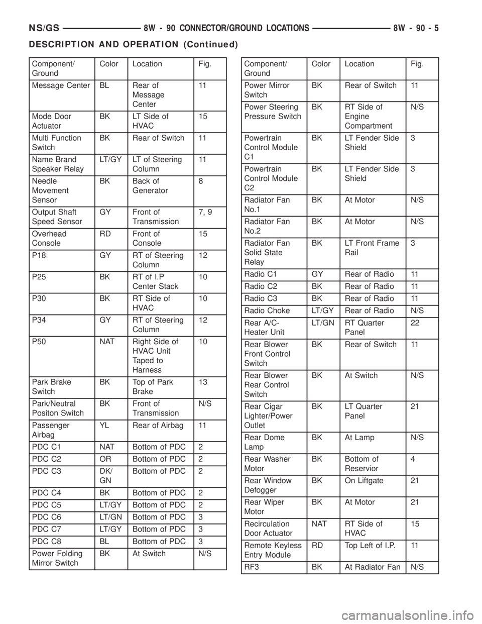
Component/
GroundColor Location Fig.
Message Center BL Rear of
Message
Center11
Mode Door
ActuatorBK LT Side of
HVAC15
Multi Function
SwitchBK Rear of Switch 11
Name Brand
Speaker RelayLT/GY LT of Steering
Column11
Needle
Movement
SensorBK Back of
Generator8
Output Shaft
Speed SensorGY Front of
Transmission7, 9
Overhead
ConsoleRD Front of
Console15
P18 GY RT of Steering
Column12
P25 BK RT of I.P
Center Stack10
P30 BK RT Side of
HVAC10
P34 GY RT of Steering
Column12
P50 NAT Right Side of
HVAC Unit
Taped to
Harness10
Park Brake
SwitchBK Top of Park
Brake13
Park/Neutral
Positon SwitchBK Front of
TransmissionN/S
Passenger
AirbagYL Rear of Airbag 11
PDC C1 NAT Bottom of PDC 2
PDC C2 OR Bottom of PDC 2
PDC C3 DK/
GNBottom of PDC 2
PDC C4 BK Bottom of PDC 2
PDC C5 LT/GY Bottom of PDC 2
PDC C6 LT/GN Bottom of PDC 3
PDC C7 LT/GY Bottom of PDC 3
PDC C8 BL Bottom of PDC 3
Power Folding
Mirror SwitchBK At Switch N/SComponent/
GroundColor Location Fig.
Power Mirror
SwitchBK Rear of Switch 11
Power Steering
Pressure SwitchBK RT Side of
Engine
CompartmentN/S
Powertrain
Control Module
C1BK LT Fender Side
Shield3
Powertrain
Control Module
C2BK LT Fender Side
Shield3
Radiator Fan
No.1BK At Motor N/S
Radiator Fan
No.2BK At Motor N/S
Radiator Fan
Solid State
RelayBK LT Front Frame
Rail3
Radio C1 GY Rear of Radio 11
Radio C2 BK Rear of Radio 11
Radio C3 BK Rear of Radio 11
Radio Choke LT/GY Rear of Radio N/S
Rear A/C-
Heater UnitLT/GN RT Quarter
Panel22
Rear Blower
Front Control
SwitchBK Rear of Switch 11
Rear Blower
Rear Control
SwitchBK At Switch N/S
Rear Cigar
Lighter/Power
OutletBK LT Quarter
Panel21
Rear Dome
LampBK At Lamp N/S
Rear Washer
MotorBK Bottom of
Reservior4
Rear Window
DefoggerBK On Liftgate 21
Rear Wiper
MotorBK At Motor 21
Recirculation
Door ActuatorNAT RT Side of
HVAC15
Remote Keyless
Entry ModuleRD Top Left of I.P. 11
RF3 BK At Radiator Fan N/S
NS/GS8W - 90 CONNECTOR/GROUND LOCATIONS 8W - 90 - 5
DESCRIPTION AND OPERATION (Continued)
Page 999 of 1938

Component/
GroundColor Location Fig.
Powertrain
Control Module
C1BK LT Fender Side
Shield3
Powertrain
Control Module
C2BK LT Fender Side
Shield3
Radiator Fan
No.1BK At Motor N/S
Radiator Fan
No.2BK At Motor N/S
Radiator Fan
RelayBK LT Front Frame
Rail3
Radio C1 GY Rear of Radio 11
Radio C2 BK Rear of Radio 11
Radio C3 BK Rear of Radio 11
Radio Choke LT/GY Rear of Radio N/S
Rear A/C-
Heater UnitLT/GN RT Quarter
Panel22
Rear Blower
Front Control
SwitchBK Rear of Switch 11
Rear Blower
Rear Control
SwitchBK At Switch N/S
Rear Cigar
Lighter/Power
OutletBK LT Quarter
Panel21
Rear Dome
LampBK At Lamp N/S
Rear Washer
MotorBK Bottom of
Reservior4
Rear Window
DefoggerBK On Liftgate 23
Rear Wiper
MotorBK At Motor 23
Recirculation
Door ActuatorNAT RT Side of
HVAC15
Remote Keyless
Entry ModuleRD Top RT of I.P. 11
Right
Combination
RelayBK LT Quarter
PanelN/S
Right Door
Arm/Disarm
SwitchBK At Switch 19
Right Door
Courtesy LampBK At Lamp 19Component/
GroundColor Location Fig.
Right Door
SpeakerBK At Speaker 19
RF3 BK At Radiator Fan
ModuleN/S
Right Fog Lamp GY At Lamp 4
Right Front
Door Ajar
SwitchBK RT B-Pillar 12
Right Front
Door Lock
MotorBK At Motor 19
Right Front
Panel SpeakerBK At Speaker 11
Right Front
Park/Turn
Signal LampBK At Lamp 4
Right Front
Wheel Speed
SensorBK Right Fender
Side Shield4
Right Front
Window MotorRD At Motor 19
Right Headlamp BK At Lamp 4
Right Headlamp
Leveling MotorBK At Motor N/S
Right Liftgate
Flood LampBK At Lamp 23
Right Mid
Reading LampGY At Lamp 17
Right Power
Door Lock
SwitchBK At Switch 19
Right Power
Mirror C1RD At Mirror 11
Right Power
Mirror C2BL At Mirror 11
Right Power
Window SwitchBK At Switch 19
Right Rear
Lamp AssemblyBK At Lamp 22
Right Rear Door
Ajar SwitchBK RT C-Pillar N/S
Right Rear Pillar
SpeakerBK At Speaker 22
Right Rear
Reading LampGY At Lamp 17
NS/GS8W - 90 CONNECTOR/GROUND LOCATIONS 8W - 90 - 35
DESCRIPTION AND OPERATION (Continued)
Page 1435 of 1938

POWER STEERING PUMP
INDEX
page page
DESCRIPTION AND OPERATION
POWER STEERING PUMP OPERATION....... 9
DIAGNOSIS AND TESTING
POWER STEERING PUMP FLOW RATE AND
PRESSURE TEST....................... 9
SERVICE PROCEDURES
POWER STEERING PUMP INITIAL
OPERATION.......................... 10
POWER STEERING SYSTEM FLUID LEVEL
CHECK.............................. 10
REMOVAL AND INSTALLATION
2.4 LITER POWER STEERING PUMP......... 11
3.0 LITER POWER STEERING PUMP........ 13
3.3/3.8 LITER POWER STEERING PUMP...... 16
POWER STEERING FLUID PRESSURE HOSE . . 19POWER STEERING FLUID RESERVOIR TO
PUMP SUPPLY HOSE................... 18
POWER STEERING FLUID RETURN HOSE.... 21
REMOTE POWER STEERING FLUID
RESERVOIR.......................... 22
DISASSEMBLY AND ASSEMBLY
POWER STEERING PUMP FLOW CONTROL
VALVE SEAL.......................... 23
POWER STEERING PUMP PULLEY.......... 23
SPECIFICATIONS
POWER STEERING PUMP FASTENER
TORQUE SPECIFICATIONS.............. 24
POWER STEERING SYSTEM
SPECIFICATIONS...................... 24
SPECIAL TOOLS
POWER STEERING PUMP................. 25
DESCRIPTION AND OPERATION
POWER STEERING PUMP OPERATION
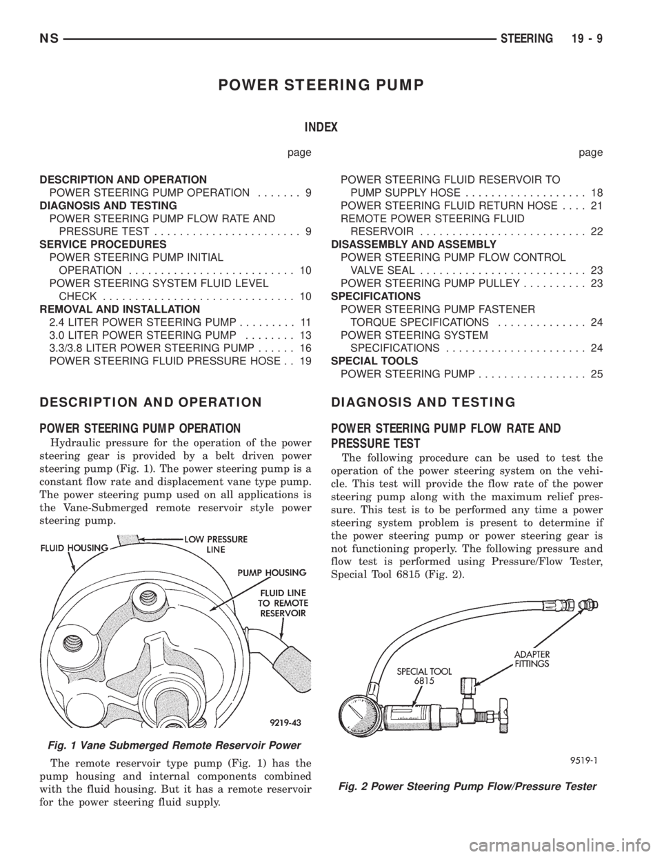
Hydraulic pressure for the operation of the power
steering gear is provided by a belt driven power
steering pump (Fig. 1). The power steering pump is a
constant flow rate and displacement vane type pump.
The power steering pump used on all applications is
the Vane-Submerged remote reservoir style power
steering pump.
The remote reservoir type pump (Fig. 1) has the
pump housing and internal components combined
with the fluid housing. But it has a remote reservoir
for the power steering fluid supply.
DIAGNOSIS AND TESTING
POWER STEERING PUMP FLOW RATE AND
PRESSURE TEST
The following procedure can be used to test the
operation of the power steering system on the vehi-
cle. This test will provide the flow rate of the power
steering pump along with the maximum relief pres-
sure. This test is to be performed any time a power
steering system problem is present to determine if
the power steering pump or power steering gear is
not functioning properly. The following pressure and
flow test is performed using Pressure/Flow Tester,
Special Tool 6815 (Fig. 2).
Fig. 1 Vane Submerged Remote Reservoir Power
Fig. 2 Power Steering Pump Flow/Pressure Tester
NSSTEERING 19 - 9