sensor CHRYSLER VOYAGER 1996 Manual PDF
[x] Cancel search | Manufacturer: CHRYSLER, Model Year: 1996, Model line: VOYAGER, Model: CHRYSLER VOYAGER 1996Pages: 1938, PDF Size: 55.84 MB
Page 323 of 1938

INSTALLATION
(1) Reverse the above procedure for installation.
ENGINE COOLANT TEMPERATURE SENSORÐ3.0L
The sensor is installed next to the thermostat
housing (Fig. 3).
WARNING: HOT, PRESSURIZED COOLANT CAN
CAUSE INJURY BY SCALDING. COOLING SYSTEM
MUST BE PARTIALLY DRAINED BEFORE REMOV-
ING THE COOLANT TEMPERATURE SENSOR.
REFER TO GROUP 7- COOLING.
REMOVAL
(1) With the engine cold, drain coolant until level
drops below cylinder head. Refer to Group 7, Cooling
System.
(2) Disconnect coolant sensor electrical connector.
(3) Remove coolant sensor.
INSTALLATION
(1) Install coolant sensor. Tighten sensor to 7 N´m
(60 in. lbs.) torque.
(2) Attach electrical connector to sensor.
(3) Fill cooling system. Refer to Group 7, Cooling
System.
CRANKSHAFT POSITION SENSOR
REMOVAL
(1) Raise and support vehicle.
(2) Disconnect crankshaft position sensor electrical
connector from the wiring harness connector (Fig. 4).
(3) Remove crankshaft position sensor retaining
bolt.
(4) Pull crankshaft position sensor straight up out
of the transaxle housing.
INSTALLATION
NOTE: If the removed sensor is to be reinstalled,
clean off the old spacer on the sensor face. A NEW
SPACER must be attached to the sensor face before
installation. If the sensor is being replaced, confirm
that the paper spacer is attached to the face of the
new sensor (Fig. 5).
(1) Install sensor in transaxle and push sensor
down until contact is made with the drive plate.
While holding the sensor in this position, and install
and tighten the retaining bolt to 11.9 N´m (105 in.
lbs.) torque.
(2) Raise and support vehicle.
(3) Connect crankshaft position sensor electrical
connector to the wiring harness connector.
THROTTLE POSITION SENSOR
Refer to Group 14, Fuel Injection Section, for
Removal/Installation.
Fig. 3 Manifold Absolute Pressure Sensor
Fig. 4 Crankshaft Position Sensor Connector
Fig. 5 Crankshaft Position Sensor and Spacer
NSIGNITION SYSTEM 8D - 25
REMOVAL AND INSTALLATION (Continued)
Page 326 of 1938

3.3/3.8L ENGINE
INDEX
page page
DESCRIPTION AND OPERATION
FIRING ORDERÐ3.3/3.8L................. 28
REMOVAL AND INSTALLATION
CAMSHAFT POSITION SENSOR............ 31
CRANKSHAFT POSITION SENSOR.......... 30
ENGINE COOLANT TEMPERATURE SENSOR . . 32
IGNITION COIL......................... 30
KNOCK SENSORÐ3.3/3.8L................ 32
MANIFOLD ABSOLUTE PRESSURE (MAP)
SENSOR............................. 32SPARK PLUG CABLE SERVICEÐ3.3/3.8L
ENGINES............................ 28
SPARK PLUG SERVICEÐ3.3/3.8L ENGINES . . . 29
THROTTLE POSITION SENSOR............ 32
SPECIFICATIONS
IGNITION COIL......................... 33
SPARK PLUG CABLE RESISTANCEÐ3.3/3.8L . . 34
SPARK PLUG........................... 33
TORQUE.............................. 34
DESCRIPTION AND OPERATION
FIRING ORDERÐ3.3/3.8L
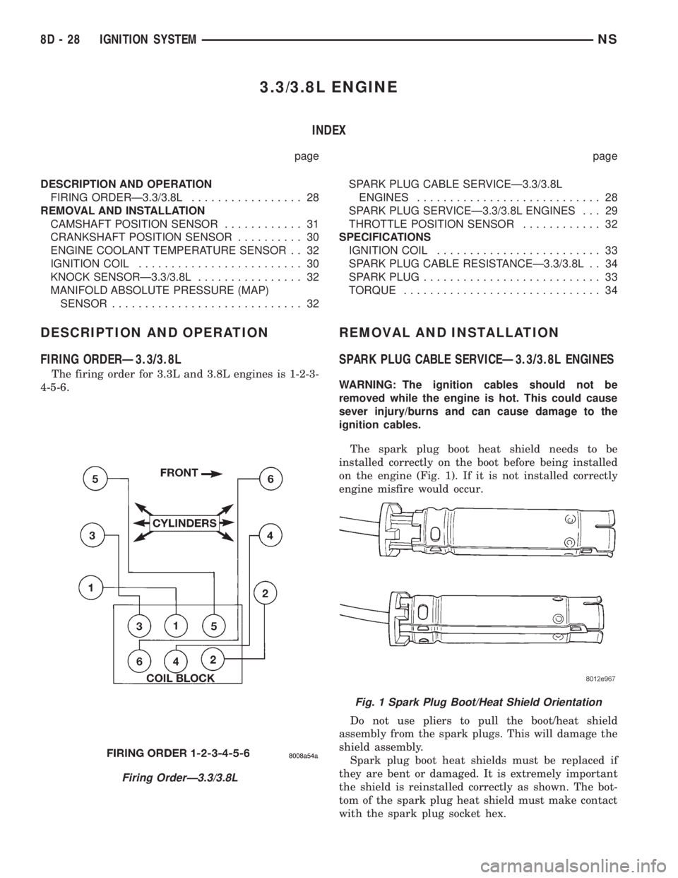
The firing order for 3.3L and 3.8L engines is 1-2-3-
4-5-6.
REMOVAL AND INSTALLATION
SPARK PLUG CABLE SERVICEÐ3.3/3.8L ENGINES
WARNING: The ignition cables should not be
removed while the engine is hot. This could cause
sever injury/burns and can cause damage to the
ignition cables.
The spark plug boot heat shield needs to be
installed correctly on the boot before being installed
on the engine (Fig. 1). If it is not installed correctly
engine misfire would occur.
Do not use pliers to pull the boot/heat shield
assembly from the spark plugs. This will damage the
shield assembly.
Spark plug boot heat shields must be replaced if
they are bent or damaged. It is extremely important
the shield is reinstalled correctly as shown. The bot-
tom of the spark plug heat shield must make contact
with the spark plug socket hex.
Firing OrderÐ3.3/3.8L
Fig. 1 Spark Plug Boot/Heat Shield Orientation
8D - 28 IGNITION SYSTEMNS
Page 328 of 1938

(5) Install intake strut bolt to cylinder head at cyl-
inder head.
(6) Tighten bolt to intake strut at intake.
(7) Tighten bolt at cylinder head.
(8) Install the resonator.
SPARK PLUG #1
REMOVAL
(1) Remove the accessory drive belt, refer to Group
7, Cooling.
(2) Remove the 4 bolts from the upper half of the
generator bracket.
(3) Push the Generator rearward.
(4) Grasp the spark plug boot/shield assembly as
close as possible to the spark plug.Twist the boot/
shield assembly slightly to break its seal with
the plug and pull straight out. Do not use pli-
ers, pull on the ignition cable, or pull the spark
plug boot at an angle.This could damage the
spark plug insulator, terminal, or the insulation.
Wipe spark plug insulator clean with a dry cloth
before installation.
(5) Remove spark plug
INSTALLATION
(1) Install spark plug and tighten to 28 N´m (20 ft.
lbs.).
(2) When installing the spark plug cables, make
sure the coil or spark plug insulator and terminals
are fully seated. Aclick sound should be heard or
felt when the terminals are properly attached.
(3) Pull Generator back into place.
(4) Install upper Generator bracket with the 4
bolts.
(5) Install the accessory drive belt, refer to Group
7, Cooling.
IGNITION COIL
REMOVAL
(1) Remove spark plug cables from coil (Fig. 2).
Always twist the spark plug boots to break the seal
with the plug and pull straight back on the boot.
(2) Remove ignition coil electrical connector.
(3) Remove ignition coil mounting screws.
(4) Remove ignition coil.
INSTALLATION
(1) Reverse the above procedure for installation.
Tighten mounting screws to 12 N´m (105 in. lbs.)
torque.
(2) Transfer spark plug cables to new coil pack.
The coil pack towers and cables are numbered with
the cylinder identification.
CRANKSHAFT POSITION SENSOR
REMOVAL
(1) Raise and support vehicle.
(2) Disconnect crankshaft position sensor electrical
connector from the wiring harness connector (Fig. 3).
(3) Remove crankshaft position sensor retaining
bolt.
(4) Pull crankshaft position sensor straight up out
of the transaxle housing.
INSTALLATION
NOTE: If the removed sensor is to be reinstalled,
clean off the old spacer on the sensor face. A NEW
SPACER must be attached to the sensor face before
installation. If the sensor is being replaced, confirm
that the paper spacer is attached to the face of the
new sensor (Fig. 4).
(1) Install sensor in transaxle and push sensor
down until contact is made with the drive plate.
Fig. 2 Ignition Coil Removal
Fig. 3 Crankshaft Position Sensor Connector
8D - 30 IGNITION SYSTEMNS
REMOVAL AND INSTALLATION (Continued)
Page 329 of 1938

While holding the sensor in this position, and install
and tighten the retaining bolt to 11.9 N´m (105 in.
lbs.) torque.
(2) Raise and support vehicle.
(3) Connect crankshaft position sensor electrical
connector to the wiring harness connector.
CAMSHAFT POSITION SENSOR
REMOVAL
(1) Disconnect camshaft position sensor electrical
connector from the wiring harness connector (Fig. 5).
(2) Remove bolt holding sensor (Fig. 6).There is a
hole in the bracket for tool access to the sensor
bolt.
(3) Rotate sensor away from block (Fig. 7).
(4) Pull sensor up out of the chain case cover.Do
not pull on the sensor lead.There is an O-ring on
the sensor case. The O-ring may make removal diffi-
cult. A light tap to top of sensor prior to removal may
reduce force needed for removal.
INSTALLATION
If the removed sensor is reinstalled, clean off
the old spacer on the sensor face. A NEW
SPACER must be attached to the face beforeinstallation.Inspect O-ring for damage, replace if
necessary. If the sensor is being replaced, confirm
that the paper spacer is attached to the face and O-
ring is positioned in groove of the new sensor (Fig. 8).
(1) Apply a couple drops of clean engine oil to the
O-ring prior to installation.
(2) Install sensor in the chain case cover and
rotate into position.
(3) Push sensor down until contact is made with
the camshaft gear. While holding the sensor in this
position, install and tighten the retaining bolt 14
N´m (125 in. lbs.) torque.
(4) Connect camshaft position sensor electrical
connector to harness connector.
Fig. 4 Crankshaft Position Sensor and Spacer
Fig. 5 Camshaft Position Sensor
Fig. 6 Camshaft Sensor Bolt Removal/Installation
Fig. 7 Camshaft Sensor Removal/Installation
NSIGNITION SYSTEM 8D - 31
REMOVAL AND INSTALLATION (Continued)
Page 330 of 1938

MANIFOLD ABSOLUTE PRESSURE (MAP) SENSOR
REMOVAL
(1) Disconnect electrical connector from MAP sen-
sor.
(2) Remove 2 screws holding sensor to intake man-
ifold (Fig. 9).
(3) Remove sensor from manifold.
INSTALLATION
Reverse the above procedure for installation.
ENGINE COOLANT TEMPERATURE SENSOR
The Engine Coolant Temperature (ECT) sensor is
located below the ignition coil (Fig. 10).
REMOVAL
(1) Drain cooling system until coolant level is
below sensor. Refer to Group 7, Cooling System.
(2) Remove electrical connector from coil (Fig. 11).
(3) Remove coil mounting screws.
(4) Rotate coil away from engine coolant tempera-
ture sensor.
(5) Disconnect electrical connector from engine
coolant temperature sensor.
(6) Remove sensor from engine.
INSTALLATION
(1) Tighten the sensor to 7 N´m (60 in. lbs.) torque.
(2) Connect electrical connector to sensor.
(3) Fill cooling system. Refer to Group 7, Cooling
System.
(4) Install coil. Tighten coil mounting screws to 12
N´m (105 in. lbs.) torque.
(5) Connect electrical connector to coil.
THROTTLE POSITION SENSOR
Refer to Group 14, Fuel Injection Section, for
Removal/Installation.
KNOCK SENSORÐ3.3/3.8L
The knock sensor threads into the side of the cyl-
inder block in front of the starter (Fig. 12).
Fig. 8 Camshaft Position Sensor and Spacer
Fig. 9 Manifold Absolute Pressure Sensor
Fig. 10 Engine Coolant Temperature Sensor
Fig. 11 Ignition Coil Removal
8D - 32 IGNITION SYSTEMNS
REMOVAL AND INSTALLATION (Continued)
Page 331 of 1938

REMOVAL
(1) Disconnect electrical connector from knock sen-
sor.
(2) Use a crow foot socket to remove the knock
sensor.
INSTALLATION
(1) Install knock sensor. Tighten knock sensor to
10 N´m (7 ft. lbs.) torque.Over or under tighten-
ing effects knock sensor performance, possibly
causing improper spark control.
(2) Attach electrical connector to knock sensor.
SPECIFICATIONS
IGNITION COILFig. 12 Knock Sensor
Coil ManufacturePrimary Resistance at 21ÉC-27ÉC
(70ÉF-80ÉF)Secondary Resistance at 21ÉC-
27ÉC (70ÉF-80ÉF)
Weastec (Aluminum Towers) 0.45 TO 0.65 Ohms 7,000 to 15,800 Ohms
Diamond Electric (Brass Towers) 0.45 TO 0.65 Ohms 7,000 to 15,800 Ohms
Coil PolarityCoil Polarity
NSIGNITION SYSTEM 8D - 33
REMOVAL AND INSTALLATION (Continued)
Page 332 of 1938

SPARK PLUG
* New Spark Plug Gap
TORQUE
DESCRIPTION......................TORQUE
3.3L Camshaft Position
Sensor Screw.............12N´m(105 in. lbs.)
3.3L Engine Coolant Sensor......7N´m(60in.lbs.)
3.3L Crankshaft Position
Sensor Screw.............12N´m(105 in. lbs.)
3.3/3.8L Ignition Coil.........12N´m(105 in. lbs.)
Ignition Switch...............2N´m(17in.lbs.)
Spark Plugs.................28N´m(20ft.lbs.)
SPARK PLUG CABLE RESISTANCEÐ3.3/3.8L
Engine Spark Plug Gap * Thread Size
3.3L RN14PMP5 0.048 TO 0.053 14mm (3/4 in.) reach
3.8L RN14PMP5 0.048 TO 0.053 14mm (3/4 in. ) reach
CABLE Maximum
Resistance
#1 18.5K ohms
#2 15.5K ohms
#3 20.4K ohms
#4 21.2K ohms
#5 27.7K ohms
#6 26.7K ohms
8D - 34 IGNITION SYSTEMNS
SPECIFICATIONS (Continued)
Page 340 of 1938

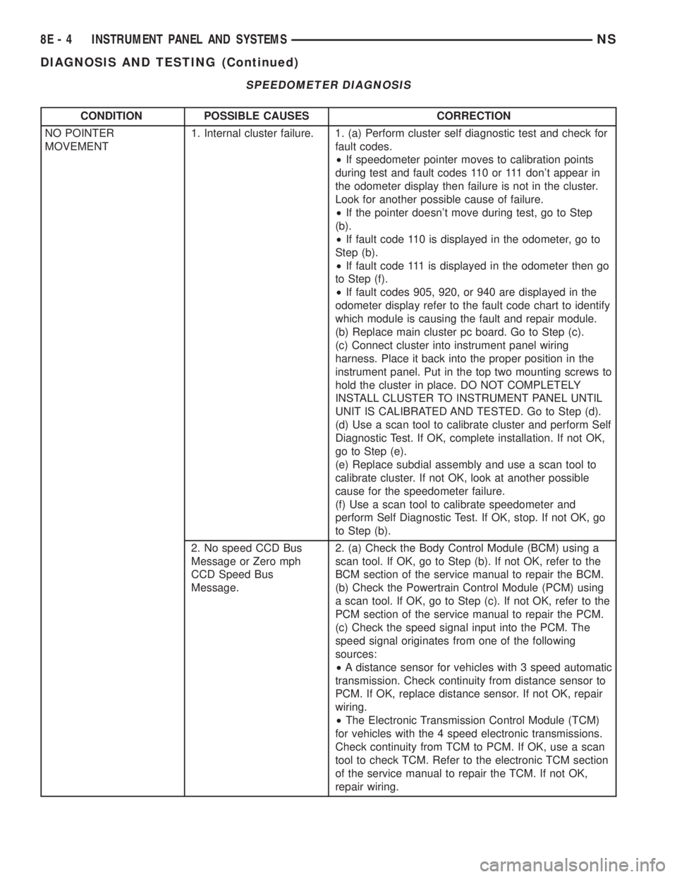
SPEEDOMETER DIAGNOSIS
CONDITION POSSIBLE CAUSES CORRECTION
NO POINTER
MOVEMENT1. Internal cluster failure. 1. (a) Perform cluster self diagnostic test and check for
fault codes.
²If speedometer pointer moves to calibration points
during test and fault codes 110 or 111 don't appear in
the odometer display then failure is not in the cluster.
Look for another possible cause of failure.
²If the pointer doesn't move during test, go to Step
(b).
²If fault code 110 is displayed in the odometer, go to
Step (b).
²If fault code 111 is displayed in the odometer then go
to Step (f).
²If fault codes 905, 920, or 940 are displayed in the
odometer display refer to the fault code chart to identify
which module is causing the fault and repair module.
(b) Replace main cluster pc board. Go to Step (c).
(c) Connect cluster into instrument panel wiring
harness. Place it back into the proper position in the
instrument panel. Put in the top two mounting screws to
hold the cluster in place. DO NOT COMPLETELY
INSTALL CLUSTER TO INSTRUMENT PANEL UNTIL
UNIT IS CALIBRATED AND TESTED. Go to Step (d).
(d) Use a scan tool to calibrate cluster and perform Self
Diagnostic Test. If OK, complete installation. If not OK,
go to Step (e).
(e) Replace subdial assembly and use a scan tool to
calibrate cluster. If not OK, look at another possible
cause for the speedometer failure.
(f) Use a scan tool to calibrate speedometer and
perform Self Diagnostic Test. If OK, stop. If not OK, go
to Step (b).
2. No speed CCD Bus
Message or Zero mph
CCD Speed Bus
Message.2. (a) Check the Body Control Module (BCM) using a
scan tool. If OK, go to Step (b). If not OK, refer to the
BCM section of the service manual to repair the BCM.
(b) Check the Powertrain Control Module (PCM) using
a scan tool. If OK, go to Step (c). If not OK, refer to the
PCM section of the service manual to repair the PCM.
(c) Check the speed signal input into the PCM. The
speed signal originates from one of the following
sources:
²A distance sensor for vehicles with 3 speed automatic
transmission. Check continuity from distance sensor to
PCM. If OK, replace distance sensor. If not OK, repair
wiring.
²The Electronic Transmission Control Module (TCM)
for vehicles with the 4 speed electronic transmissions.
Check continuity from TCM to PCM. If OK, use a scan
tool to check TCM. Refer to the electronic TCM section
of the service manual to repair the TCM. If not OK,
repair wiring.
8E - 4 INSTRUMENT PANEL AND SYSTEMSNS
DIAGNOSIS AND TESTING (Continued)
Page 341 of 1938

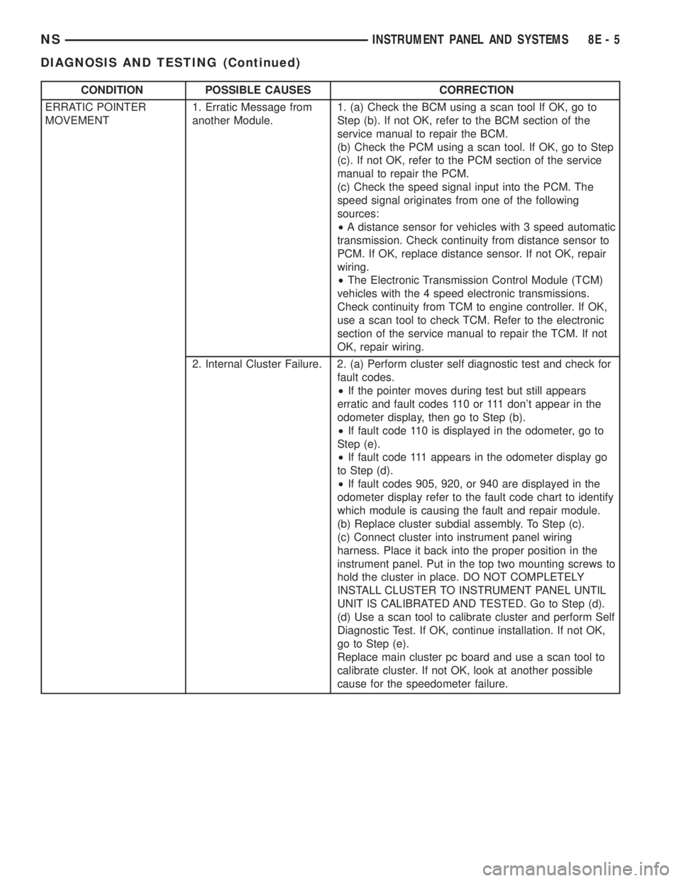
CONDITION POSSIBLE CAUSES CORRECTION
ERRATIC POINTER
MOVEMENT1. Erratic Message from
another Module.1. (a) Check the BCM using a scan tool If OK, go to
Step (b). If not OK, refer to the BCM section of the
service manual to repair the BCM.
(b) Check the PCM using a scan tool. If OK, go to Step
(c). If not OK, refer to the PCM section of the service
manual to repair the PCM.
(c) Check the speed signal input into the PCM. The
speed signal originates from one of the following
sources:
²A distance sensor for vehicles with 3 speed automatic
transmission. Check continuity from distance sensor to
PCM. If OK, replace distance sensor. If not OK, repair
wiring.
²The Electronic Transmission Control Module (TCM)
vehicles with the 4 speed electronic transmissions.
Check continuity from TCM to engine controller. If OK,
use a scan tool to check TCM. Refer to the electronic
section of the service manual to repair the TCM. If not
OK, repair wiring.
2. Internal Cluster Failure. 2. (a) Perform cluster self diagnostic test and check for
fault codes.
²If the pointer moves during test but still appears
erratic and fault codes 110 or 111 don't appear in the
odometer display, then go to Step (b).
²If fault code 110 is displayed in the odometer, go to
Step (e).
²If fault code 111 appears in the odometer display go
to Step (d).
²If fault codes 905, 920, or 940 are displayed in the
odometer display refer to the fault code chart to identify
which module is causing the fault and repair module.
(b) Replace cluster subdial assembly. To Step (c).
(c) Connect cluster into instrument panel wiring
harness. Place it back into the proper position in the
instrument panel. Put in the top two mounting screws to
hold the cluster in place. DO NOT COMPLETELY
INSTALL CLUSTER TO INSTRUMENT PANEL UNTIL
UNIT IS CALIBRATED AND TESTED. Go to Step (d).
(d) Use a scan tool to calibrate cluster and perform Self
Diagnostic Test. If OK, continue installation. If not OK,
go to Step (e).
Replace main cluster pc board and use a scan tool to
calibrate cluster. If not OK, look at another possible
cause for the speedometer failure.
NSINSTRUMENT PANEL AND SYSTEMS 8E - 5
DIAGNOSIS AND TESTING (Continued)
Page 342 of 1938

CONDITION POSSIBLE CAUSES CORRECTION
SPEEDOMETER
INACCURATE.1. Speedometer Out of
Calibration.1. (a) Perform Cluster Self Diagnostic Test.
²If speedometer is accurate to the calibration points
then look for another possible cause of inaccuracy.
²If speedometer is not accurate to the calibration
points, go to Step (b).
(b) Use a scan tool to calibrate speedometer.
2. Wrong Speedometer
Pinion Size For Tire Size.2. (a) If vehicle has a 4 speed electronic transmission
go to Step (c). Otherwise go to Step (b).
(b) Check if correct speedometer pinion is being used
with tires on vehicle. Refer to transmission section of
manual for test and repair procedure.
²If the incorrect pinion is in transmission then replace
with correct pinion.
²If the correct pinion is in the transmission calibrate
speedometer using a scan tool to correct for the
inaccuracy.
(c) use a scan tool to check the TCM to see if the
correct tire size has been programmed into the TCM.
²If the incorrect tire size was selected, select the
proper tire size.
²If the correct tire size was selected, calibrate
speedometer to correct for the inaccuracy.
3. Bad Speed Sensor. 3. Refer to the proper section of the service manual for
test and repair procedure.
8E - 6 INSTRUMENT PANEL AND SYSTEMSNS
DIAGNOSIS AND TESTING (Continued)