coolant temperature CHRYSLER VOYAGER 1996 Manual Online
[x] Cancel search | Manufacturer: CHRYSLER, Model Year: 1996, Model line: VOYAGER, Model: CHRYSLER VOYAGER 1996Pages: 1938, PDF Size: 55.84 MB
Page 1356 of 1938
circuit information. If the resistance is greater than 1
ohm, repair the wire harness as necessary.
THROTTLE POSITION SENSOR
To perform a complete test of the this sensor and
its circuitry, refer to the DRB scan tool and appropri-
ate Powertrain Diagnostics Procedures manual. To
test the throttle position sensor only, refer to the fol-
lowing:
The Throttle Position Sensor (TPS) can be tested
with a digital voltmeter (DVM). The center terminal
of the sensor is the output terminal. One of the other
terminals is a 5 volt supply and the remaining ter-
minal is ground.
Connect the DVM between the center and sensor
ground terminal. Refer to Group 8W - Wiring Dia-
grams for correct pinout.
With the ignition switch in the ON position, check
the output voltage at the center terminal wire of the
connector. Check the output voltage at idle and at
Wide-Open-Throttle (WOT). At idle, TPS output volt-
age should be approximately 0.38 volts to 1.2 volts.
At wide open throttle, TPS output voltage should be
approximately 3.1 volts to 4.4 volts. The output volt-
age should gradually increase as the throttle plate
moves slowly from idle to WOT.
Check for spread terminals at the sensor and PCM
connections before replacing the TPS.
THROTTLE BODY MINIMUM AIR FLOW CHECK
PROCEDURE
(1) Warm engine in Park or Neutral until the cool-
ing fan has cycled on and off at least once.
(2) Ensure that all accessories are off.
(3) Shut off engine.
(4)3.0L Engine
(a) Hook-up the timing check device and tachom-
eter.(b) Disconnect the engine coolant temperature
sensor and set basic timing to 12É BTDC62É.
(c) Shut off engine. Reconnect coolant tempera-
ture sensor wire.
(5) Disconnect the PCV valve hose from the intake
manifold nipple (Fig. 101), (Fig. 102) or (Fig. 103).
(6) Cap the PCV valve nipple.
(7)3.3/3.8L Engines
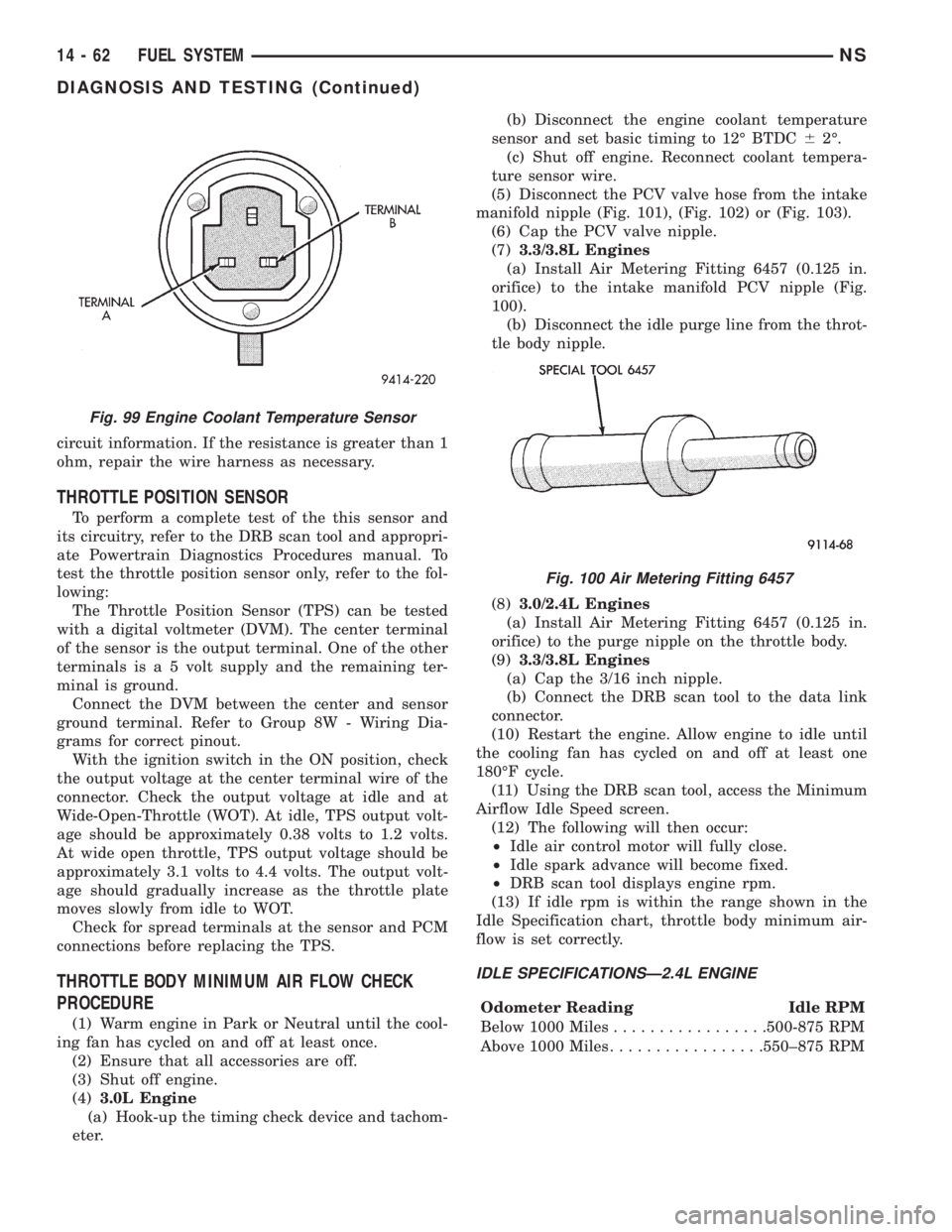
(a) Install Air Metering Fitting 6457 (0.125 in.
orifice) to the intake manifold PCV nipple (Fig.
100).
(b) Disconnect the idle purge line from the throt-
tle body nipple.
(8)3.0/2.4L Engines
(a) Install Air Metering Fitting 6457 (0.125 in.
orifice) to the purge nipple on the throttle body.
(9)3.3/3.8L Engines
(a) Cap the 3/16 inch nipple.
(b) Connect the DRB scan tool to the data link
connector.
(10) Restart the engine. Allow engine to idle until
the cooling fan has cycled on and off at least one
180ÉF cycle.
(11) Using the DRB scan tool, access the Minimum
Airflow Idle Speed screen.
(12) The following will then occur:
²Idle air control motor will fully close.
²Idle spark advance will become fixed.
²DRB scan tool displays engine rpm.
(13) If idle rpm is within the range shown in the
Idle Specification chart, throttle body minimum air-
flow is set correctly.
IDLE SPECIFICATIONSÐ2.4L ENGINE
Odometer Reading Idle RPM
Below 1000 Miles.................500-875 RPM
Above 1000 Miles.................550±875 RPM
Fig. 99 Engine Coolant Temperature Sensor
Fig. 100 Air Metering Fitting 6457
14 - 62 FUEL SYSTEMNS
DIAGNOSIS AND TESTING (Continued)
Page 1364 of 1938
(5) When the sensor is removed, the exhaust man-
ifold threads must be cleaned with an 18 mm X 1.5 +
6E tap. If using original sensor, coat the threads with
Loctite 771-64 anti-seize compound or equivalent.
INSTALLATION
(1) Reverse removal procedure to install a new
sensor.
New sensors are packaged with compound on the
threads and no additional compound is required. The
sensor must be tightened to 27 N´m (20 ft. lbs.)
torque.
KNOCK SENSOR
For removal/installation procedures refer to Group
8D- Ignition System, Service Procedures.
AIR CLEANER ELEMENT
REMOVAL
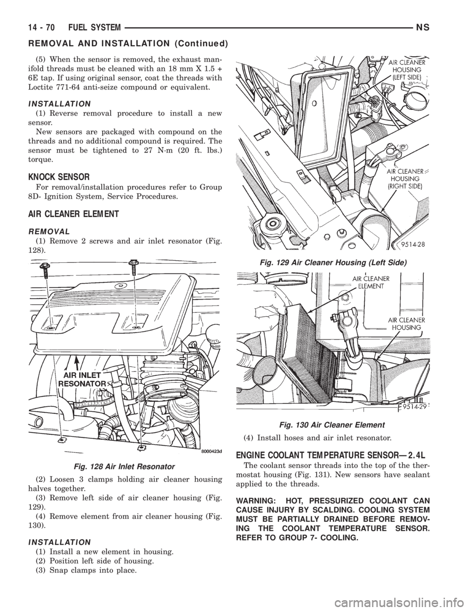
(1) Remove 2 screws and air inlet resonator (Fig.
128).
(2) Loosen 3 clamps holding air cleaner housing
halves together.
(3) Remove left side of air cleaner housing (Fig.
129).
(4) Remove element from air cleaner housing (Fig.
130).
INSTALLATION
(1) Install a new element in housing.
(2) Position left side of housing.
(3) Snap clamps into place.(4) Install hoses and air inlet resonator.
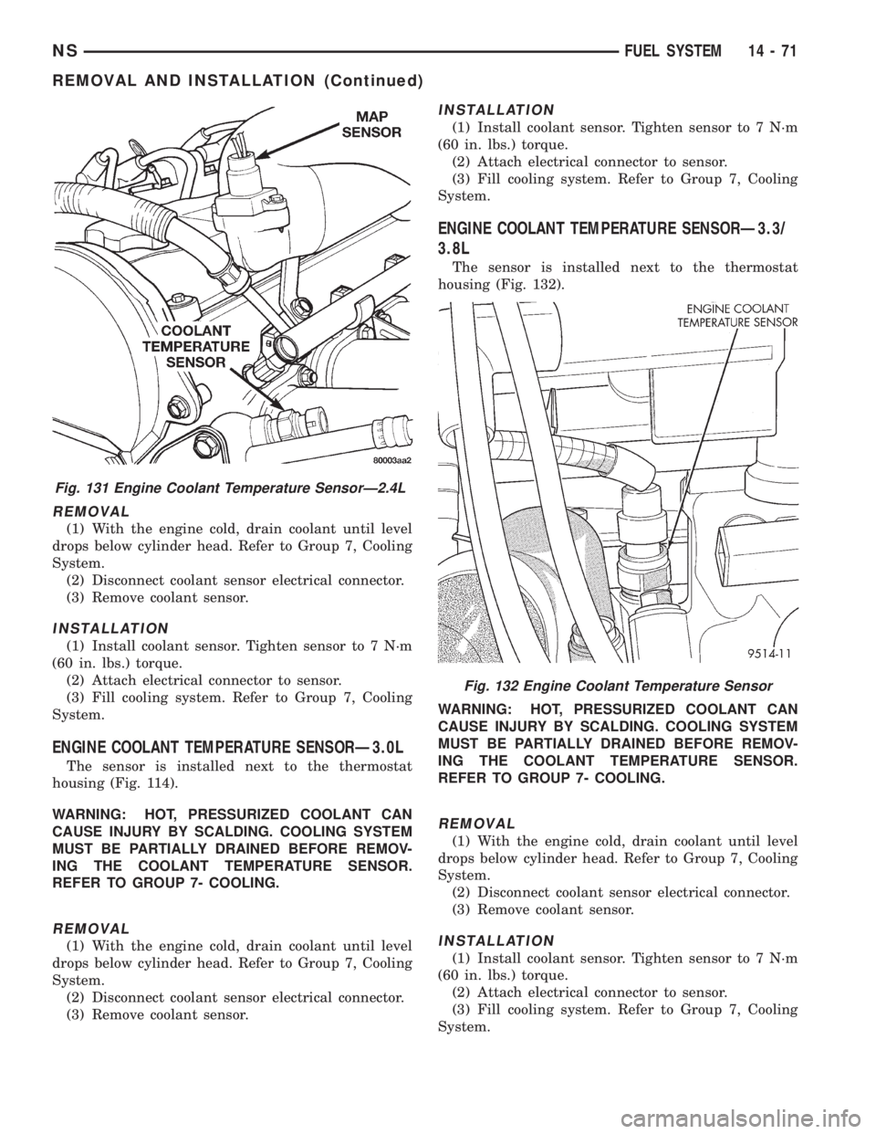
ENGINE COOLANT TEMPERATURE SENSORÐ2.4L
The coolant sensor threads into the top of the ther-
mostat housing (Fig. 131). New sensors have sealant
applied to the threads.
WARNING: HOT, PRESSURIZED COOLANT CAN
CAUSE INJURY BY SCALDING. COOLING SYSTEM
MUST BE PARTIALLY DRAINED BEFORE REMOV-
ING THE COOLANT TEMPERATURE SENSOR.
REFER TO GROUP 7- COOLING.Fig. 128 Air Inlet Resonator
Fig. 129 Air Cleaner Housing (Left Side)
Fig. 130 Air Cleaner Element
14 - 70 FUEL SYSTEMNS
REMOVAL AND INSTALLATION (Continued)
Page 1365 of 1938
REMOVAL
(1) With the engine cold, drain coolant until level
drops below cylinder head. Refer to Group 7, Cooling
System.
(2) Disconnect coolant sensor electrical connector.
(3) Remove coolant sensor.
INSTALLATION
(1) Install coolant sensor. Tighten sensor to 7 N´m
(60 in. lbs.) torque.
(2) Attach electrical connector to sensor.
(3) Fill cooling system. Refer to Group 7, Cooling
System.
ENGINE COOLANT TEMPERATURE SENSORÐ3.0L
The sensor is installed next to the thermostat
housing (Fig. 114).
WARNING: HOT, PRESSURIZED COOLANT CAN
CAUSE INJURY BY SCALDING. COOLING SYSTEM
MUST BE PARTIALLY DRAINED BEFORE REMOV-
ING THE COOLANT TEMPERATURE SENSOR.
REFER TO GROUP 7- COOLING.
REMOVAL
(1) With the engine cold, drain coolant until level
drops below cylinder head. Refer to Group 7, Cooling
System.
(2) Disconnect coolant sensor electrical connector.
(3) Remove coolant sensor.
INSTALLATION
(1) Install coolant sensor. Tighten sensor to 7 N´m
(60 in. lbs.) torque.
(2) Attach electrical connector to sensor.
(3) Fill cooling system. Refer to Group 7, Cooling
System.
ENGINE COOLANT TEMPERATURE SENSORÐ3.3/
3.8L
The sensor is installed next to the thermostat
housing (Fig. 132).
WARNING: HOT, PRESSURIZED COOLANT CAN
CAUSE INJURY BY SCALDING. COOLING SYSTEM
MUST BE PARTIALLY DRAINED BEFORE REMOV-
ING THE COOLANT TEMPERATURE SENSOR.
REFER TO GROUP 7- COOLING.
REMOVAL
(1) With the engine cold, drain coolant until level
drops below cylinder head. Refer to Group 7, Cooling
System.
(2) Disconnect coolant sensor electrical connector.
(3) Remove coolant sensor.
INSTALLATION
(1) Install coolant sensor. Tighten sensor to 7 N´m
(60 in. lbs.) torque.
(2) Attach electrical connector to sensor.
(3) Fill cooling system. Refer to Group 7, Cooling
System.
Fig. 131 Engine Coolant Temperature SensorÐ2.4L
Fig. 132 Engine Coolant Temperature Sensor
NSFUEL SYSTEM 14 - 71
REMOVAL AND INSTALLATION (Continued)
Page 1366 of 1938
INTAKE AIR TEMPERATURE SENSORÐ2.4L
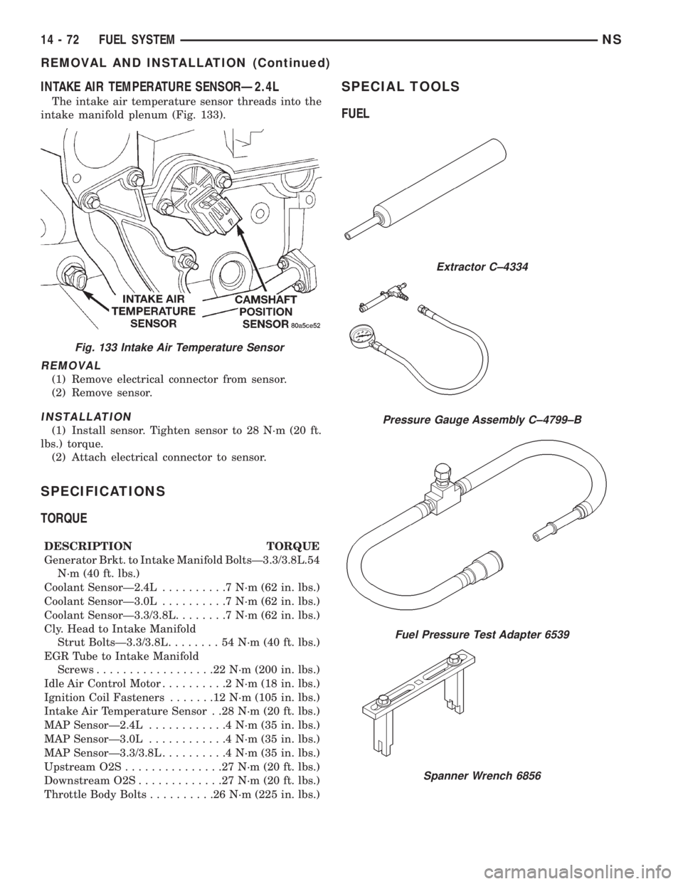
The intake air temperature sensor threads into the
intake manifold plenum (Fig. 133).
REMOVAL
(1) Remove electrical connector from sensor.
(2) Remove sensor.
INSTALLATION
(1) Install sensor. Tighten sensor to 28 N´m (20 ft.
lbs.) torque.
(2) Attach electrical connector to sensor.
SPECIFICATIONS
TORQUE
DESCRIPTION TORQUE
Generator Brkt. to Intake Manifold BoltsÐ3.3/3.8L.54
N´m (40 ft. lbs.)
Coolant SensorÐ2.4L..........7N´m(62in.lbs.)
Coolant SensorÐ3.0L..........7N´m(62in.lbs.)
Coolant SensorÐ3.3/3.8L........7N´m(62in.lbs.)
Cly. Head to Intake Manifold
Strut BoltsÐ3.3/3.8L........54N´m(40ft.lbs.)
EGR Tube to Intake Manifold
Screws..................22N´m(200 in. lbs.)
Idle Air Control Motor..........2N´m(18in.lbs.)
Ignition Coil Fasteners.......12N´m(105 in. lbs.)
Intake Air Temperature Sensor . .28 N´m (20 ft. lbs.)
MAP SensorÐ2.4L............4N´m(35in.lbs.)
MAP SensorÐ3.0L............4N´m(35in.lbs.)
MAP SensorÐ3.3/3.8L..........4N´m(35in.lbs.)
Upstream O2S...............27N´m(20ft.lbs.)
Downstream O2S.............27N´m(20ft.lbs.)
Throttle Body Bolts..........26N´m(225 in. lbs.)
SPECIAL TOOLS
FUEL
Fig. 133 Intake Air Temperature Sensor
Extractor C±4334
Pressure Gauge Assembly C±4799±B
Fuel Pressure Test Adapter 6539
Spanner Wrench 6856
14 - 72 FUEL SYSTEMNS
REMOVAL AND INSTALLATION (Continued)
Page 1373 of 1938
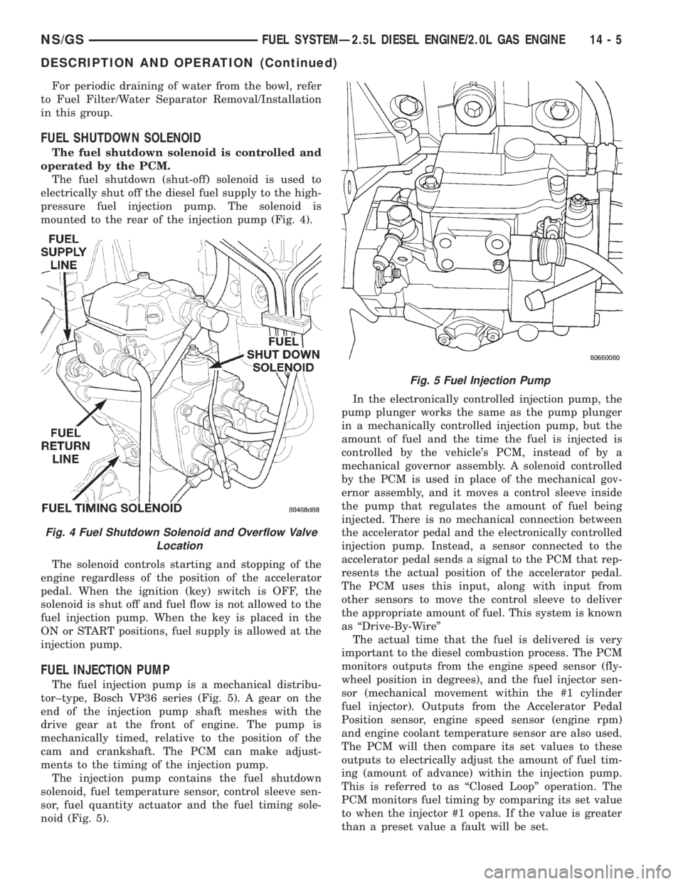
For periodic draining of water from the bowl, refer
to Fuel Filter/Water Separator Removal/Installation
in this group.
FUEL SHUTDOWN SOLENOID
The fuel shutdown solenoid is controlled and
operated by the PCM.
The fuel shutdown (shut-off) solenoid is used to
electrically shut off the diesel fuel supply to the high-
pressure fuel injection pump. The solenoid is
mounted to the rear of the injection pump (Fig. 4).
The solenoid controls starting and stopping of the
engine regardless of the position of the accelerator
pedal. When the ignition (key) switch is OFF, the
solenoid is shut off and fuel flow is not allowed to the
fuel injection pump. When the key is placed in the
ON or START positions, fuel supply is allowed at the
injection pump.
FUEL INJECTION PUMP
The fuel injection pump is a mechanical distribu-
tor±type, Bosch VP36 series (Fig. 5). A gear on the
end of the injection pump shaft meshes with the
drive gear at the front of engine. The pump is
mechanically timed, relative to the position of the
cam and crankshaft. The PCM can make adjust-
ments to the timing of the injection pump.
The injection pump contains the fuel shutdown
solenoid, fuel temperature sensor, control sleeve sen-
sor, fuel quantity actuator and the fuel timing sole-
noid (Fig. 5).In the electronically controlled injection pump, the
pump plunger works the same as the pump plunger
in a mechanically controlled injection pump, but the
amount of fuel and the time the fuel is injected is
controlled by the vehicle's PCM, instead of by a
mechanical governor assembly. A solenoid controlled
by the PCM is used in place of the mechanical gov-
ernor assembly, and it moves a control sleeve inside
the pump that regulates the amount of fuel being
injected. There is no mechanical connection between
the accelerator pedal and the electronically controlled
injection pump. Instead, a sensor connected to the
accelerator pedal sends a signal to the PCM that rep-
resents the actual position of the accelerator pedal.
The PCM uses this input, along with input from
other sensors to move the control sleeve to deliver
the appropriate amount of fuel. This system is known
as ªDrive-By-Wireº
The actual time that the fuel is delivered is very
important to the diesel combustion process. The PCM
monitors outputs from the engine speed sensor (fly-
wheel position in degrees), and the fuel injector sen-
sor (mechanical movement within the #1 cylinder
fuel injector). Outputs from the Accelerator Pedal
Position sensor, engine speed sensor (engine rpm)
and engine coolant temperature sensor are also used.
The PCM will then compare its set values to these
outputs to electrically adjust the amount of fuel tim-
ing (amount of advance) within the injection pump.
This is referred to as ªClosed Loopº operation. The
PCM monitors fuel timing by comparing its set value
to when the injector #1 opens. If the value is greater
than a preset value a fault will be set.
Fig. 4 Fuel Shutdown Solenoid and Overflow Valve
Location
Fig. 5 Fuel Injection Pump
NS/GSFUEL SYSTEMÐ2.5L DIESEL ENGINE/2.0L GAS ENGINE 14 - 5
DESCRIPTION AND OPERATION (Continued)
Page 1378 of 1938
(7) Inspect the starter motor and starter solenoid
connections for tightness and corrosion.
(8) Verify that the electrical connector is firmly
connected to the fuel shutdown solenoid. Inspect the
connector for corrosion or damaged wires. The sole-
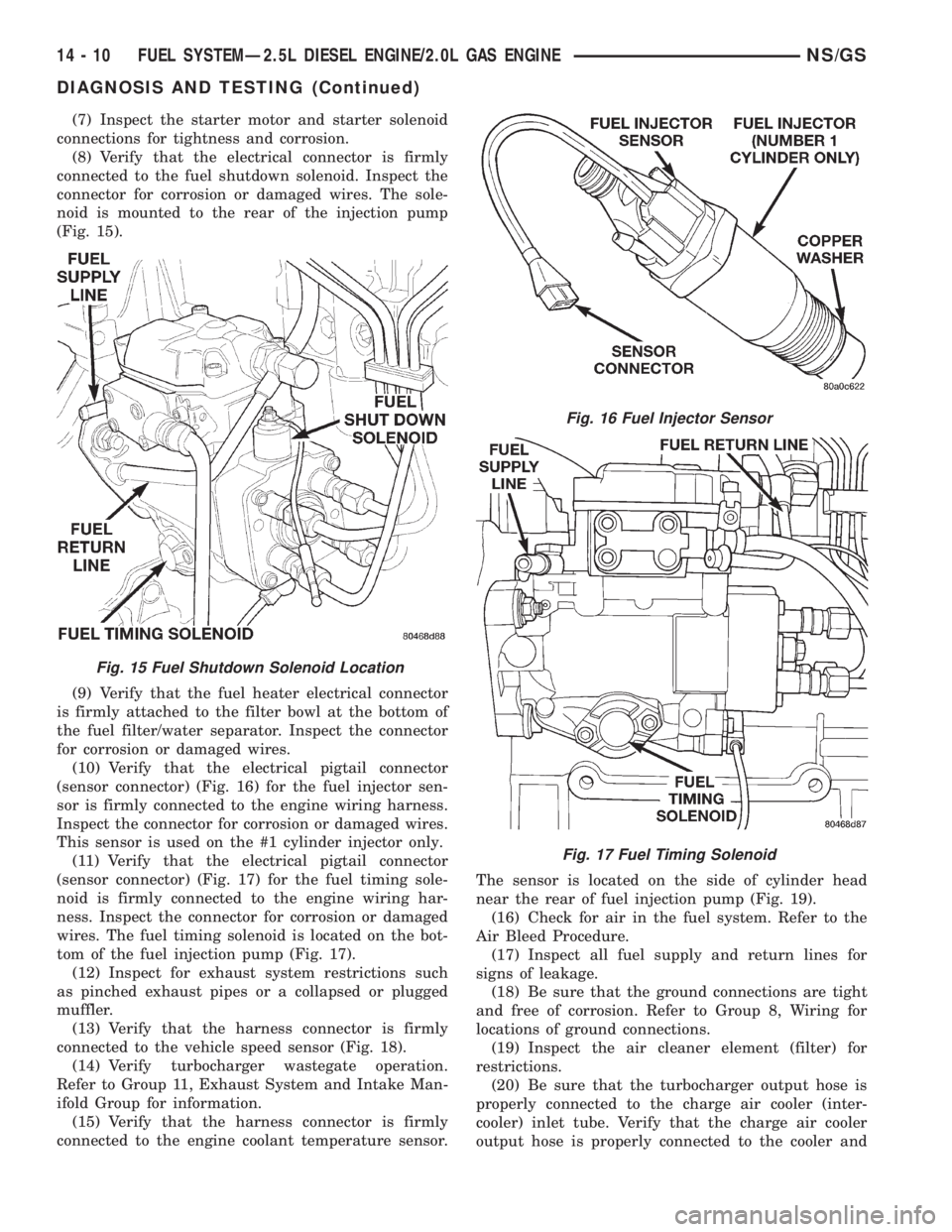
noid is mounted to the rear of the injection pump
(Fig. 15).
(9) Verify that the fuel heater electrical connector
is firmly attached to the filter bowl at the bottom of
the fuel filter/water separator. Inspect the connector
for corrosion or damaged wires.
(10) Verify that the electrical pigtail connector
(sensor connector) (Fig. 16) for the fuel injector sen-
sor is firmly connected to the engine wiring harness.
Inspect the connector for corrosion or damaged wires.
This sensor is used on the #1 cylinder injector only.
(11) Verify that the electrical pigtail connector
(sensor connector) (Fig. 17) for the fuel timing sole-
noid is firmly connected to the engine wiring har-
ness. Inspect the connector for corrosion or damaged
wires. The fuel timing solenoid is located on the bot-
tom of the fuel injection pump (Fig. 17).
(12) Inspect for exhaust system restrictions such
as pinched exhaust pipes or a collapsed or plugged
muffler.
(13) Verify that the harness connector is firmly
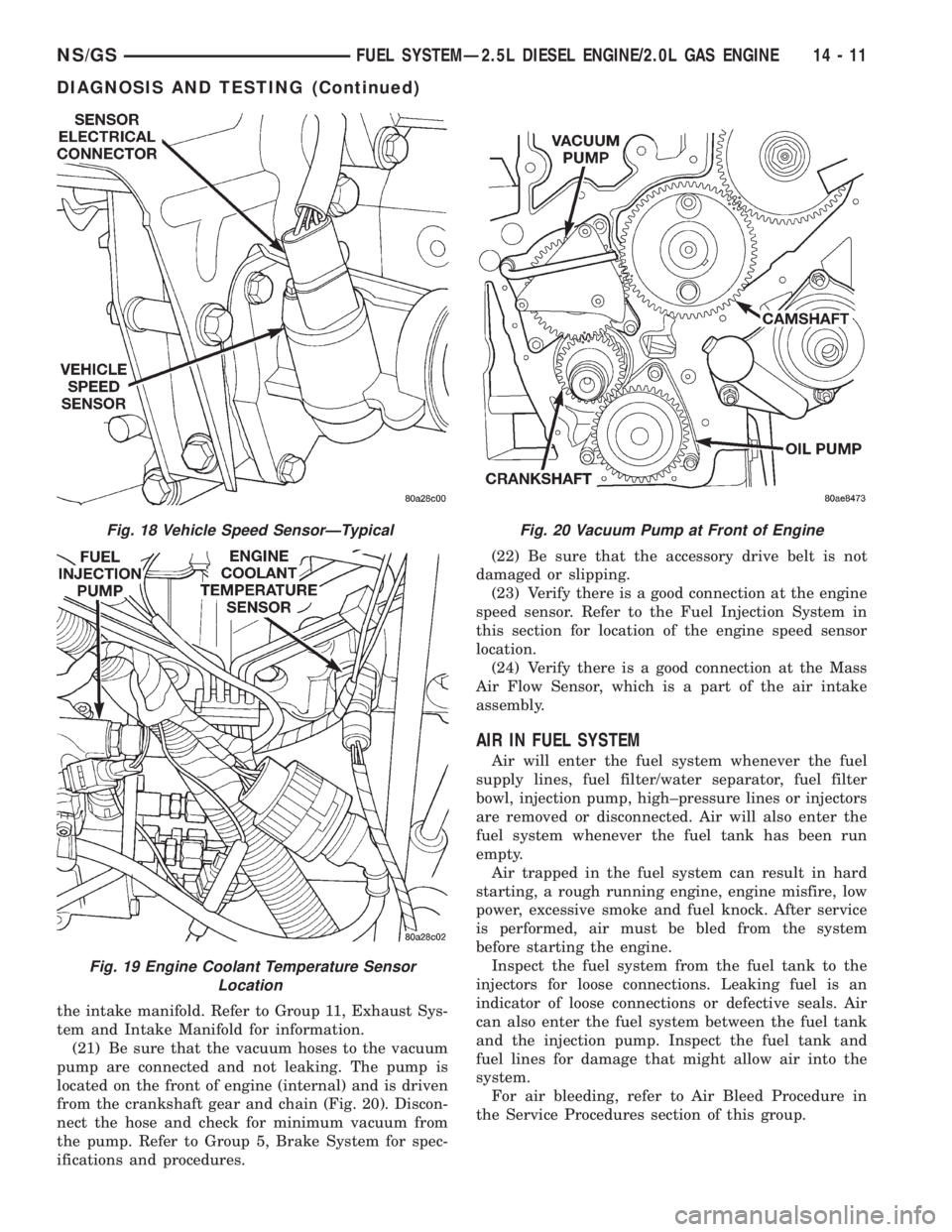
connected to the vehicle speed sensor (Fig. 18).
(14) Verify turbocharger wastegate operation.
Refer to Group 11, Exhaust System and Intake Man-
ifold Group for information.
(15) Verify that the harness connector is firmly
connected to the engine coolant temperature sensor.The sensor is located on the side of cylinder head
near the rear of fuel injection pump (Fig. 19).
(16) Check for air in the fuel system. Refer to the
Air Bleed Procedure.
(17) Inspect all fuel supply and return lines for
signs of leakage.
(18) Be sure that the ground connections are tight
and free of corrosion. Refer to Group 8, Wiring for
locations of ground connections.
(19) Inspect the air cleaner element (filter) for
restrictions.
(20) Be sure that the turbocharger output hose is
properly connected to the charge air cooler (inter-
cooler) inlet tube. Verify that the charge air cooler
output hose is properly connected to the cooler and
Fig. 15 Fuel Shutdown Solenoid Location
Fig. 16 Fuel Injector Sensor
Fig. 17 Fuel Timing Solenoid
14 - 10 FUEL SYSTEMÐ2.5L DIESEL ENGINE/2.0L GAS ENGINENS/GS
DIAGNOSIS AND TESTING (Continued)
Page 1379 of 1938
the intake manifold. Refer to Group 11, Exhaust Sys-
tem and Intake Manifold for information.
(21) Be sure that the vacuum hoses to the vacuum
pump are connected and not leaking. The pump is
located on the front of engine (internal) and is driven
from the crankshaft gear and chain (Fig. 20). Discon-
nect the hose and check for minimum vacuum from
the pump. Refer to Group 5, Brake System for spec-
ifications and procedures.(22) Be sure that the accessory drive belt is not
damaged or slipping.
(23) Verify there is a good connection at the engine
speed sensor. Refer to the Fuel Injection System in
this section for location of the engine speed sensor
location.
(24) Verify there is a good connection at the Mass
Air Flow Sensor, which is a part of the air intake
assembly.
AIR IN FUEL SYSTEM
Air will enter the fuel system whenever the fuel
supply lines, fuel filter/water separator, fuel filter
bowl, injection pump, high±pressure lines or injectors
are removed or disconnected. Air will also enter the
fuel system whenever the fuel tank has been run
empty.
Air trapped in the fuel system can result in hard
starting, a rough running engine, engine misfire, low
power, excessive smoke and fuel knock. After service
is performed, air must be bled from the system
before starting the engine.
Inspect the fuel system from the fuel tank to the
injectors for loose connections. Leaking fuel is an
indicator of loose connections or defective seals. Air
can also enter the fuel system between the fuel tank
and the injection pump. Inspect the fuel tank and
fuel lines for damage that might allow air into the
system.
For air bleeding, refer to Air Bleed Procedure in
the Service Procedures section of this group.
Fig. 18 Vehicle Speed SensorÐTypical
Fig. 19 Engine Coolant Temperature Sensor
Location
Fig. 20 Vacuum Pump at Front of Engine
NS/GSFUEL SYSTEMÐ2.5L DIESEL ENGINE/2.0L GAS ENGINE 14 - 11
DIAGNOSIS AND TESTING (Continued)
Page 1388 of 1938

(8) Disconnect the main engine wiring harness
from the glow plugs.
(9) Disconnect the four high±pressure fuel lines
from the fuel injection pump. Also disconnect fuel
lines at the fuel injectors. For procedures, refer to
High±Pressure Fuel Lines in this group. Place a rag
beneath the fittings to catch excess fuel.
(10) Remove plug from timing gear cover.
(11) The ªTop Dead Centerº (TDC) compression fir-
ing stroke must be determined as follows:
(a) Remove the valve cover, refer to Group 9,
Valve Cover Removal/Installation.
(b) Remove the right front tire and splash
shield. Using a socket attached to the end of crank-
shaft, rotate the engine (counterÐclockwise as
viewed from front).
(c) Rotate the engine until cylinder #4 rockers
are in between movement.
(d) Remove rocker arm assembly.
(e) Remove valve spring and keepers.CAU-
TION: When the piston is at TDC there is only
2 mm (.080 thousand) clearance between the
valve and piston.
(f) Let the valve set on top of piston. Install a
dial indicator to the top of the valve stem.
(g) Rotate engine back and forth to find the TDC
position with the indicator on the valve stem. Mark
the damper and timing cover for TDC.
NOTE: On later model 1997 engines, a hole in the
bottom of the clutch housing can be lined up with a
hole in the flywheel, allowing the engine to be held
at TDC with a special alignment tool, part # VM1035.(12) Remove injection pump drive gear nut (Fig.
41) and washer.CAUTION: Be very careful not to
drop the washer into the timing gear cover.
(13) A special 3±piece gear removal tool set
VM.1003 (Fig. 42) must be used to remove the injec-
tion pump drive gear from the pump shaft.
(a) Thread the adapter (Fig. 43) into the timing
cover.
(b) Thread the gear puller into the injection
pump drive gear (Fig. 43). This tool is also used to
hold the gear in synchronization during pump
removal.
(c) Remove the three injection pump±to±gear
cover mounting nuts (Fig. 44).CAUTION: This
step must be done to prevent breakage of the
Fig. 40 Engine Coolant Temperature Sensor
Fig. 41 Removing Pump Drive Gear Nut
Fig. 42 Pump Gear Tools
14 - 20 FUEL SYSTEMÐ2.5L DIESEL ENGINE/2.0L GAS ENGINENS/GS
REMOVAL AND INSTALLATION (Continued)
Page 1390 of 1938

(14) Gauge reading should be at 0.60 mm. If not,
the pump must be rotated for adjustment:
(a) Loosen the three injection pump mounting
nuts at the mounting flanges. These flanges are
equipped with slotted holes. The slotted holes are
used to rotate and position the injection pump for
fuel timing. Loosen the three nuts just enough to
rotate the pump.
(b) Rotate the pumpclockwise(as viewed from
front) until .60 mm is indicated on the dial indica-
tor gauge.
(c) Tighten the three pump mounting nuts to 30
N´m (22 ft. lbs.) torque.
(d) Recheck the dial indicator after tightening
the pump mounting nuts. Gauge should still be
reading 0.60 mm. Loosen pump mounting nuts and
readjust if necessary.
(15) Remove dial indicator and adapter tools.
(16) Install access plug and washer to rear of
injection pump.
(17) Install plug at timing gear cover.
(18) Remove dial indicator from valve stem.
(19) Install valve spring and keepers.
(20) Install rocker arm assembly and tighten nuts.
(21) Install and connect the four high±pressure
fuel lines to the fuel injection pump. Also connect
fuel lines at the fuel injectors. For procedures, refer
to High±Pressure Fuel Lines in this group.
(22) Install electrical connector at engine coolant
temperature sensor.
(23) Connect electrical connector at fuel shutdown
solenoid.(24) Connect the main engine wiring harness to
the glow plugs.
(25) Connect the fuel timing solenoid pigtail har-
ness to the engine wiring harness.
(26) Connect the overflow valve/banjo fitting (fuel
return line assembly). Replace copper gaskets before
installing.
(27) Connect the rubber fuel return and supply
hoses to metal lines at pump. Tighten hose clamps to
2 N´m (20 in. lbs.) torque.
(28) Install generator assembly.
(29) Install engine accessory drive belt. Refer to
Group 7, Cooling System for procedures.
(30) Install negative battery cable to battery.
(31) Start the engine and bring to normal operat-
ing temperature.
(32) Check for fuel leaks.
FUEL INJECTORS
Four fuel injectors are used on each engine. Of these
four, two different types are used. The fuel injector used
on cylinder number one is equipped with a fuel injector
sensor (Fig. 47). The other three fuel injectors are iden-
tical.
Do not place the fuel injector equipped with
the fuel injector sensor into any other location
except the cylinder number one position.
REMOVAL
(1) Disconnect negative battery cable at battery.
(2) Thoroughly clean the area around the injector
with compressed air.
(3) Remove the fuel drain hoses (tubes) at each
injector (Fig. 48) being serviced. Each of these hoses
is slip±fit to the fitting on injector.
(4) Remove the high±pressure fuel line at injector
being removed. Refer to High±Pressure Fuel Lines in
this group for procedures.
(5) Remove the injector using special socket tool
number VM.1012A. When removing cylinder number
Fig. 46 Installing Dial Indicator and Special Adapter
Tools
Fig. 47 Fuel Injector SensorÐNumber±1 Cylinder
14 - 22 FUEL SYSTEMÐ2.5L DIESEL ENGINE/2.0L GAS ENGINENS/GS
REMOVAL AND INSTALLATION (Continued)
Page 1400 of 1938
FUEL INJECTION SYSTEMÐ2.0L ENGINE
INDEX
page page
GENERAL INFORMATION
INTRODUCTIONÐ2.0L ENGINE............ 32
MODES OF OPERATIONÐ2.0L ENGINE..... 32
DESCRIPTION AND OPERATION
AIR CONDITIONING (A/C) RELAYÐPCM
OUTPUTÐ2.0L ENGINE................ 35
AIR CONDITIONING PRESSURE
TRANSDUCERÐPCM INPUTÐ
2.0L ENGINE......................... 33
AIR CONDITIONING SWITCH SENSEÐ
PCM INPUTÐ2.0L ENGINE.............. 33
AUTOMATIC SHUTDOWN (ASD) SENSEÐ
PCM INPUTÐ2.0L ENGINE.............. 33
AUTOMATIC SHUTDOWN RELAYÐ
PCM OUTPUTÐ2.0L ENGINE............ 35
BATTERY VOLTAGEÐPCM INPUTÐ
2.0L ENGINE......................... 33
CAMSHAFT POSITION SENSORÐ
PCM INPUTÐ2.0L ENGINE.............. 33
CRANKSHAFT POSITION SENSORÐ
PCM INPUTÐ2.0L ENGINE.............. 33
DATA LINK CONNECTORÐPCM OUTPUTÐ
2.0L ENGINE......................... 35
ELECTRONIC EGR TRANSDUCERÐ
PCM OUTPUTÐ2.0L ENGINE............ 35
ENGINE COOLANT TEMPERATURE SENSORÐ
PCM INPUTÐ2.0L ENGINE.............. 33
FUEL INJECTORSÐPCM OUTPUTÐ
2.0L ENGINE......................... 35
FUEL PUMP RELAYÐPCM OUTPUTÐ
2.0L ENGINE......................... 35
GENERATOR FIELDÐPCM OUTPUTÐ
2.0L ENGINE......................... 35
HEATED OXYGEN SENSORÐPCM INPUTÐ
2.0L ENGINE......................... 33
IDLE AIR CONTROL MOTORÐPCM OUTPUTÐ
2.0L ENGINE......................... 35
IGNITION COILÐPCM OUTPUTÐ
2.0L ENGINE......................... 36KNOCK SENSORÐPCM INPUTÐ
2.0L ENGINE......................... 34
MALFUNCTION INDICATOR (CHECK ENGINE)
LAMPÐPCM OUTPUTÐ2.0L ENGINE...... 36
MANIFOLD ABSOLUTE PRESSURE
(MAP SENSOR)ÐPCM INPUTÐ
2.0L ENGINE......................... 34
POWERTRAIN CONTROL MODULEÐ
2.0L ENGINE......................... 33
RADIATOR FAN CONTROL MODULEÐ
PCM OUTPUTÐ2.0L ENGINE............ 36
SPEED CONTROL SOLENOIDSÐ
PCM OUTPUTÐ2.0L ENGINE............ 36
SPEED CONTROLÐPCM INPUTÐ
2.0L ENGINE......................... 34
STARTER RELAYÐPCM OUTPUTÐ
2.0L ENGINE......................... 35
SYSTEM DIAGNOSISÐ2.0L ENGINE........ 33
TACHOMETERÐPCM OUTPUTÐ
2.0L ENGINE......................... 36
THROTTLE BODYÐ2.0L ENGINE.......... 36
THROTTLE POSITION SENSOR/ IDLE AIR
CONTROL MOTORÐPCM INPUTÐ
2.0L ENGINE......................... 35
DIAGNOSIS AND TESTING
ASD AND FUEL PUMP RELAYSÐ
2.0L ENGINE......................... 39
CAMSHAFT AND CRANKSHAFT
POSITION SENSOR................... 40
ENGINE COOLANT TEMPERATURE
SENSOR............................ 40
KNOCK SENSORÐ2.0L ENGINE........... 40
MANIFOLD ABSOLUTE PRESSURE
(MAP) SENSORÐ2.0L ENGINE........... 39
THROTTLE BODY MINIMUM AIR FLOW..... 41
THROTTLE POSITION SENSOR........... 40
VISUAL INSPECTIONÐSOHC............. 36
SPECIFICATIONS
TORQUE............................. 42
GENERAL INFORMATION
INTRODUCTIONÐ2.0L ENGINE
Refer to the Introduction for 2.4/3.0/3.3/3.8L
engines under General Information in the Fuel Injec-
tion System section of group 14 for more information.
MODES OF OPERATIONÐ2.0L ENGINE
Refer to the Modes of Operation for 2.4/3.0/3.3/3.8L
engines under General Information in the Fuel Injec-
tion System section of group 14 for more information.
14 - 32 FUEL SYSTEMÐ2.5L DIESEL ENGINE/2.0L GAS ENGINENS/GS