bolt pattern CHRYSLER VOYAGER 1996 Service Manual
[x] Cancel search | Manufacturer: CHRYSLER, Model Year: 1996, Model line: VOYAGER, Model: CHRYSLER VOYAGER 1996Pages: 1938, PDF Size: 55.84 MB
Page 42 of 1938
Mc PHERSON STRUT ASSEMBLY
The front suspension of the vehicle is supported by
coil springs positioned around the strut assembly.
The springs are contained between an upper seat,
located just below the top strut mount assembly and
a lower spring seat on the strut fluid reservoir.
The top of each strut assembly is bolted to the
upper fender reinforcement (strut tower) through a
rubber isolated mount.
The bottom of the strut assembly attaches to the
steering knuckle with two through bolts. Caster is a
fixed setting on all vehicles and is not adjustable
when an alignment is performed. In the event the
camber setting on a vehicle requires adjustment, a
service strut is available which will provide a method
by which the camber can be adjusted.
The strut assemblies on this vehicle are inter-con-
nected by the front stabilizer bar through 2 link
assemblies attaching the struts to the stabilizer bar.
STEERING KNUCKLE
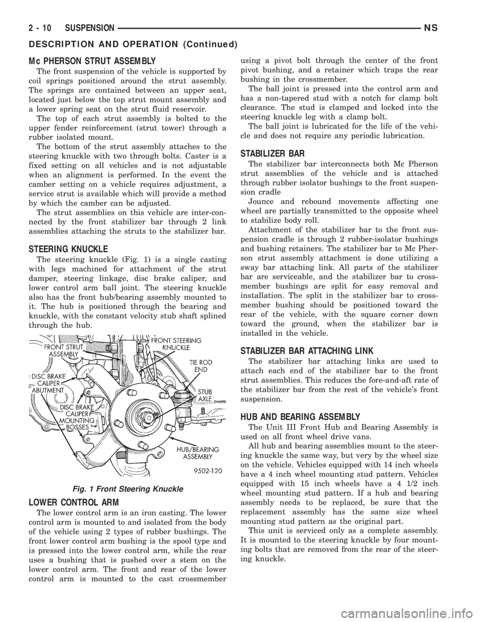
The steering knuckle (Fig. 1) is a single casting
with legs machined for attachment of the strut
damper, steering linkage, disc brake caliper, and
lower control arm ball joint. The steering knuckle
also has the front hub/bearing assembly mounted to
it. The hub is positioned through the bearing and
knuckle, with the constant velocity stub shaft splined
through the hub.
LOWER CONTROL ARM
The lower control arm is an iron casting. The lower
control arm is mounted to and isolated from the body
of the vehicle using 2 types of rubber bushings. The
front lower control arm bushing is the spool type and
is pressed into the lower control arm, while the rear
uses a bushing that is pushed over a stem on the
lower control arm. The front and rear of the lower
control arm is mounted to the cast crossmemberusing a pivot bolt through the center of the front
pivot bushing, and a retainer which traps the rear
bushing in the crossmember.
The ball joint is pressed into the control arm and
has a non-tapered stud with a notch for clamp bolt
clearance. The stud is clamped and locked into the
steering knuckle leg with a clamp bolt.
The ball joint is lubricated for the life of the vehi-
cle and does not require any periodic lubrication.
STABILIZER BAR
The stabilizer bar interconnects both Mc Pherson
strut assemblies of the vehicle and is attached
through rubber isolator bushings to the front suspen-
sion cradle
Jounce and rebound movements affecting one
wheel are partially transmitted to the opposite wheel
to stabilize body roll.
Attachment of the stabilizer bar to the front sus-
pension cradle is through 2 rubber-isolator bushings
and bushing retainers. The stabilizer bar to Mc Pher-
son strut assembly attachment is done utilizing a
sway bar attaching link. All parts of the stabilizer
bar are serviceable, and the stabilizer bar to cross-
member bushings are split for easy removal and
installation. The split in the stabilizer bar to cross-
member bushing should be positioned toward the
rear of the vehicle, with the square corner down
toward the ground, when the stabilizer bar is
installed in the vehicle.
STABILIZER BAR ATTACHING LINK
The stabilizer bar attaching links are used to
attach each end of the stabilizer bar to the front
strut assemblies. This reduces the fore-and-aft rate of
the stabilizer bar from the rest of the vehicle's front
suspension.
HUB AND BEARING ASSEMBLY
The Unit III Front Hub and Bearing Assembly is
used on all front wheel drive vans.
All hub and bearing assemblies mount to the steer-
ing knuckle the same way, but very by the wheel size
on the vehicle. Vehicles equipped with 14 inch wheels
have a 4 inch wheel mounting stud pattern. Vehicles
equipped with 15 inch wheels have a 4 1/2 inch
wheel mounting stud pattern. If a hub and bearing
assembly needs to be replaced, be sure that the
replacement assembly has the same size wheel
mounting stud pattern as the original part.
This unit is serviced only as a complete assembly.
It is mounted to the steering knuckle by four mount-
ing bolts that are removed from the rear of the steer-
ing knuckle.
Fig. 1 Front Steering Knuckle
2 - 10 SUSPENSIONNS
DESCRIPTION AND OPERATION (Continued)
Page 59 of 1938
INSTALL
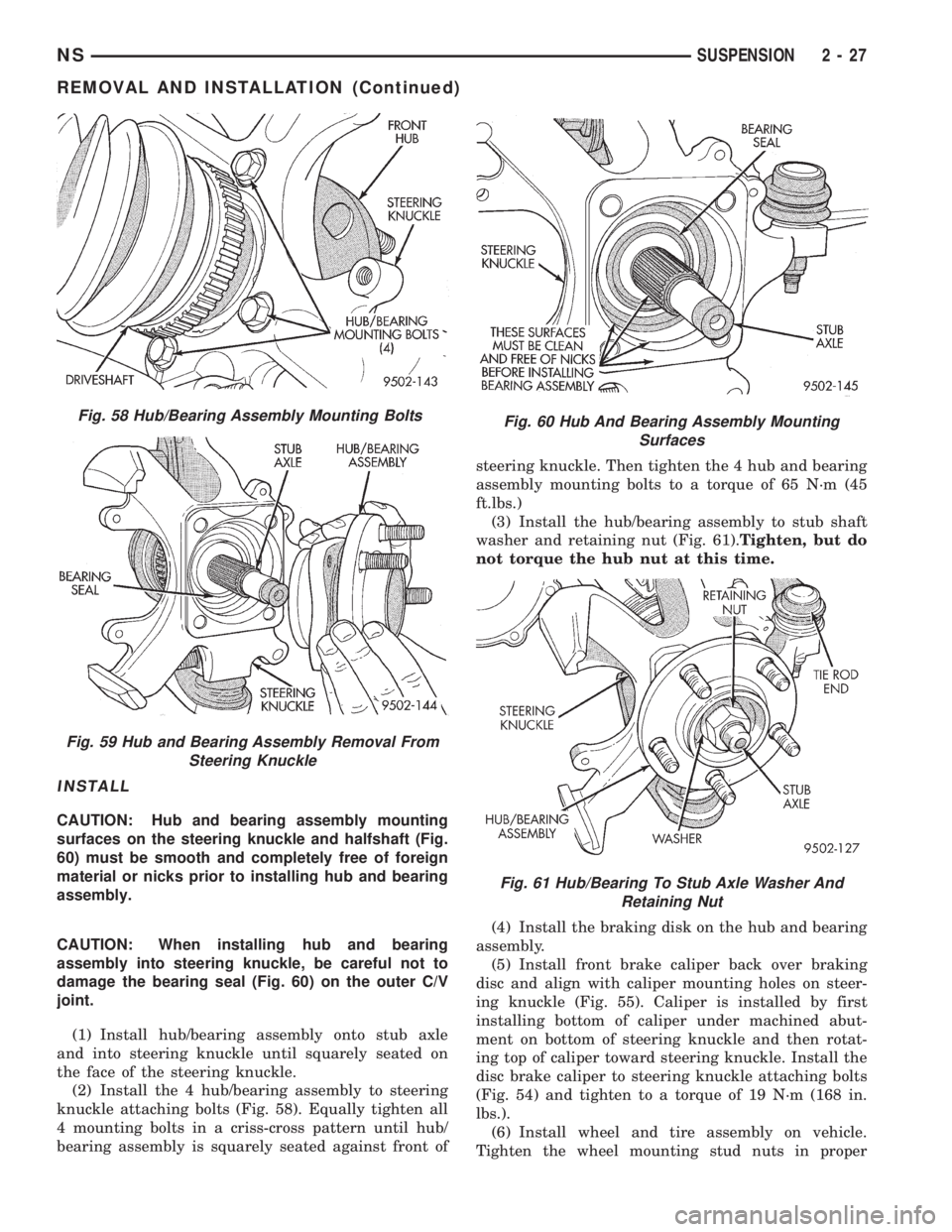
CAUTION: Hub and bearing assembly mounting
surfaces on the steering knuckle and halfshaft (Fig.
60) must be smooth and completely free of foreign
material or nicks prior to installing hub and bearing
assembly.
CAUTION: When installing hub and bearing
assembly into steering knuckle, be careful not to
damage the bearing seal (Fig. 60) on the outer C/V
joint.
(1) Install hub/bearing assembly onto stub axle
and into steering knuckle until squarely seated on
the face of the steering knuckle.
(2) Install the 4 hub/bearing assembly to steering
knuckle attaching bolts (Fig. 58). Equally tighten all
4 mounting bolts in a criss-cross pattern until hub/
bearing assembly is squarely seated against front ofsteering knuckle. Then tighten the 4 hub and bearing
assembly mounting bolts to a torque of 65 N´m (45
ft.lbs.)
(3) Install the hub/bearing assembly to stub shaft
washer and retaining nut (Fig. 61).Tighten, but do
not torque the hub nut at this time.
(4) Install the braking disk on the hub and bearing
assembly.
(5) Install front brake caliper back over braking
disc and align with caliper mounting holes on steer-
ing knuckle (Fig. 55). Caliper is installed by first
installing bottom of caliper under machined abut-
ment on bottom of steering knuckle and then rotat-
ing top of caliper toward steering knuckle. Install the
disc brake caliper to steering knuckle attaching bolts
(Fig. 54) and tighten to a torque of 19 N´m (168 in.
lbs.).
(6) Install wheel and tire assembly on vehicle.
Tighten the wheel mounting stud nuts in proper
Fig. 58 Hub/Bearing Assembly Mounting Bolts
Fig. 59 Hub and Bearing Assembly Removal From
Steering Knuckle
Fig. 60 Hub And Bearing Assembly Mounting
Surfaces
Fig. 61 Hub/Bearing To Stub Axle Washer And
Retaining Nut
NSSUSPENSION 2 - 27
REMOVAL AND INSTALLATION (Continued)
Page 121 of 1938
INSTALL
(1) Install the 4 hub/bearing to axle mounting
bolts into the mounting holes in the flange of the
rear axle.
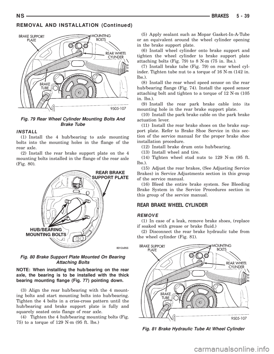
(2) Install the rear brake support plate on the 4
mounting bolts installed in the flange of the rear axle
(Fig. 80).
NOTE: When installing the hub/bearing on the rear
axle, the bearing is to be installed with the thick
bearing mounting flange (Fig. 77) pointing down.
(3) Align the rear hub/bearing with the 4 mount-
ing bolts and start mounting bolts into hub/bearing.
Tighten the 4 bolts in a criss-cross pattern until the
hub/bearing and brake support plate is fully and
squarely seated onto flange of rear axle.
(4) Tighten the 4 hub/bearing mounting bolts (Fig.
75) to a torque of 129 N´m (95 ft. lbs.)(5) Apply sealant such as Mopar Gasket-In-A-Tube
or an equivalent around the wheel cylinder opening
in the brake support plate.
(6) Install wheel cylinder onto brake support and
tighten the wheel cylinder to brake support plate
attaching bolts (Fig. 79) to 8 N´m (75 in. lbs.).
(7) Install brake tube (Fig. 79) on rear wheel cyl-
inder. Tighten tube nut to a torque of 16 N´m (142 in.
lbs.).
(8) Install the rear wheel speed sensor on the rear
hub/bearing flange (Fig. 74). Install the speed sensor
attaching bolt and tighten to a torque of 12 N´m (105
in. lbs.).
(9) Install the rear park brake cable into its
mounting hole in the rear brake support plate.
(10) Install the park brake cable on the park brake
actuation lever.
(11) Install the rear brake shoes on the brake sup-
port plate. Refer to Brake Shoe Service in this sec-
tion of the service manual for the proper brake shoe
installation procedure.
(12) Install brake drum onto hub/bearing.
(13) Install wheel and tire.
(14) Tighten wheel stud nuts to 129 N´m (95 ft.
lbs.).
(15) Adjust the rear brakes, (See Adjusting Service
Brakes) in Service Adjustments section in this group
of the service manual.
(16) Bleed the entire brake system. See Bleeding
Brake System in the Service Procedures section in
this group of the service manual.
REAR BRAKE WHEEL CYLINDER
REMOVE
(1) In case of a leak, remove brake shoes, (replace
if soaked with grease or brake fluid.)
(2) Disconnect the rear brake hydraulic tube from
the wheel cylinder (Fig. 81).
Fig. 79 Rear Wheel Cylinder Mounting Bolts And
Brake Tube
Fig. 80 Brake Support Plate Mounted On Bearing
Attaching Bolts
Fig. 81 Brake Hydraulic Tube At Wheel Cylinder
NSBRAKES 5 - 39
REMOVAL AND INSTALLATION (Continued)
Page 123 of 1938
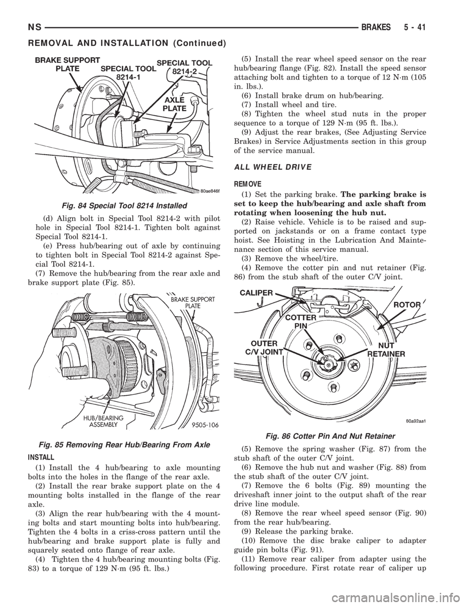
(d) Align bolt in Special Tool 8214-2 with pilot
hole in Special Tool 8214-1. Tighten bolt against
Special Tool 8214-1.
(e) Press hub/bearing out of axle by continuing
to tighten bolt in Special Tool 8214-2 against Spe-
cial Tool 8214-1.
(7) Remove the hub/bearing from the rear axle and
brake support plate (Fig. 85).
INSTALL
(1) Install the 4 hub/bearing to axle mounting
bolts into the holes in the flange of the rear axle.
(2) Install the rear brake support plate on the 4
mounting bolts installed in the flange of the rear
axle.
(3) Align the rear hub/bearing with the 4 mount-
ing bolts and start mounting bolts into hub/bearing.
Tighten the 4 bolts in a criss-cross pattern until the
hub/bearing and brake support plate is fully and
squarely seated onto flange of rear axle.
(4) Tighten the 4 hub/bearing mounting bolts (Fig.
83) to a torque of 129 N´m (95 ft. lbs.)(5) Install the rear wheel speed sensor on the rear
hub/bearing flange (Fig. 82). Install the speed sensor
attaching bolt and tighten to a torque of 12 N´m (105
in. lbs.).
(6) Install brake drum on hub/bearing.
(7) Install wheel and tire.
(8) Tighten the wheel stud nuts in the proper
sequence to a torque of 129 N´m (95 ft. lbs.).
(9) Adjust the rear brakes, (See Adjusting Service
Brakes) in Service Adjustments section in this group
of the service manual.
ALL WHEEL DRIVE
REMOVE
(1) Set the parking brake.The parking brake is
set to keep the hub/bearing and axle shaft from
rotating when loosening the hub nut.
(2) Raise vehicle. Vehicle is to be raised and sup-
ported on jackstands or on a frame contact type
hoist. See Hoisting in the Lubrication And Mainte-
nance section of this service manual.
(3) Remove the wheel/tire.
(4) Remove the cotter pin and nut retainer (Fig.
86) from the stub shaft of the outer C/V joint.
(5) Remove the spring washer (Fig. 87) from the
stub shaft of the outer C/V joint.
(6) Remove the hub nut and washer (Fig. 88) from
the stub shaft of the outer C/V joint.
(7) Remove the 6 bolts (Fig. 89) mounting the
driveshaft inner joint to the output shaft of the rear
drive line module.
(8) Remove the rear wheel speed sensor (Fig. 90)
from the rear hub/bearing.
(9) Release the parking brake.
(10) Remove the disc brake caliper to adapter
guide pin bolts (Fig. 91).
(11) Remove rear caliper from adapter using the
following procedure. First rotate rear of caliper up
Fig. 84 Special Tool 8214 Installed
Fig. 85 Removing Rear Hub/Bearing From Axle
Fig. 86 Cotter Pin And Nut Retainer
NSBRAKES 5 - 41
REMOVAL AND INSTALLATION (Continued)
Page 125 of 1938
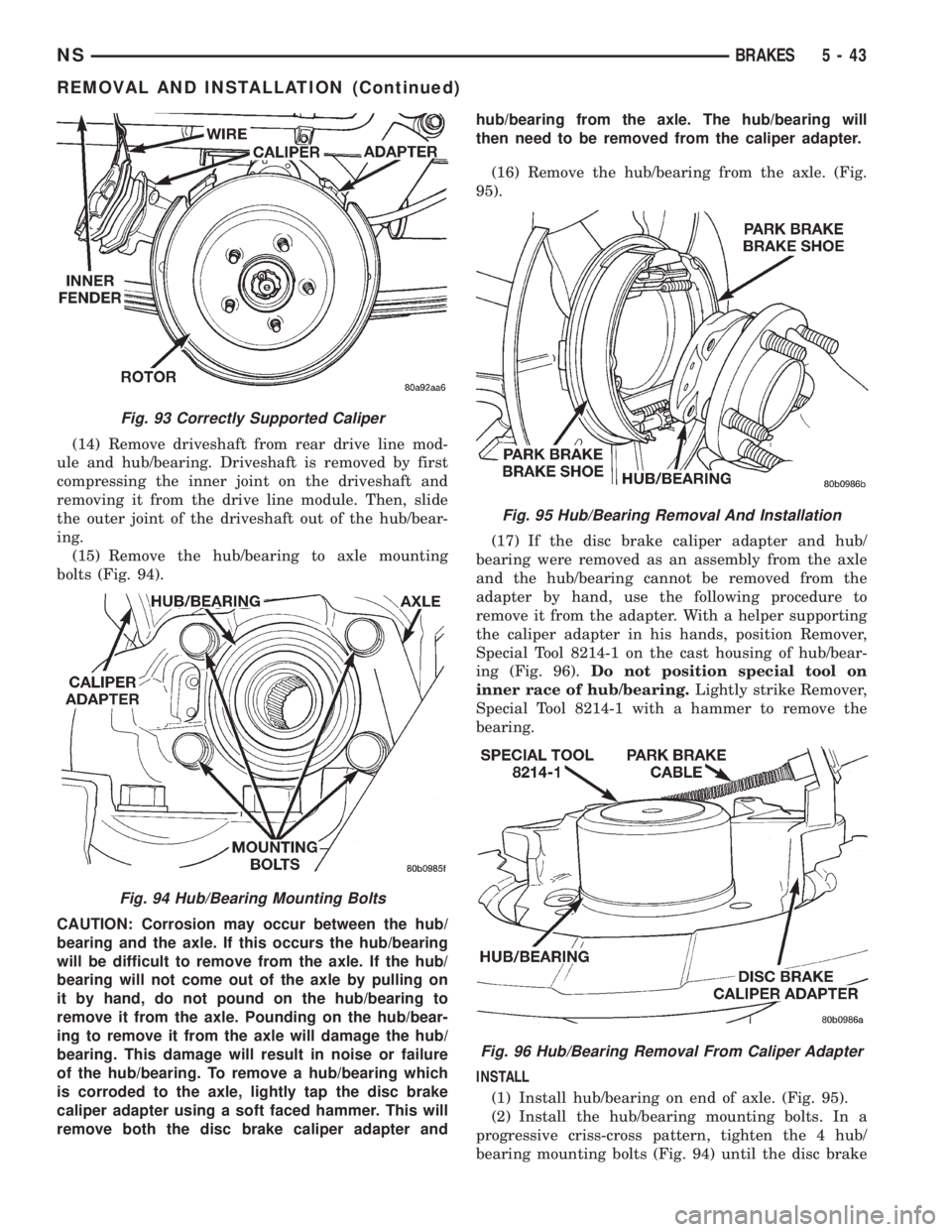
(14) Remove driveshaft from rear drive line mod-
ule and hub/bearing. Driveshaft is removed by first
compressing the inner joint on the driveshaft and
removing it from the drive line module. Then, slide
the outer joint of the driveshaft out of the hub/bear-
ing.
(15) Remove the hub/bearing to axle mounting
bolts (Fig. 94).
CAUTION: Corrosion may occur between the hub/
bearing and the axle. If this occurs the hub/bearing
will be difficult to remove from the axle. If the hub/
bearing will not come out of the axle by pulling on
it by hand, do not pound on the hub/bearing to
remove it from the axle. Pounding on the hub/bear-
ing to remove it from the axle will damage the hub/
bearing. This damage will result in noise or failure
of the hub/bearing. To remove a hub/bearing which
is corroded to the axle, lightly tap the disc brake
caliper adapter using a soft faced hammer. This will
remove both the disc brake caliper adapter andhub/bearing from the axle. The hub/bearing will
then need to be removed from the caliper adapter.
(16) Remove the hub/bearing from the axle. (Fig.
95).
(17) If the disc brake caliper adapter and hub/
bearing were removed as an assembly from the axle
and the hub/bearing cannot be removed from the
adapter by hand, use the following procedure to
remove it from the adapter. With a helper supporting
the caliper adapter in his hands, position Remover,
Special Tool 8214-1 on the cast housing of hub/bear-
ing (Fig. 96).Do not position special tool on
inner race of hub/bearing.Lightly strike Remover,
Special Tool 8214-1 with a hammer to remove the
bearing.
INSTALL
(1) Install hub/bearing on end of axle. (Fig. 95).
(2) Install the hub/bearing mounting bolts. In a
progressive criss-cross pattern, tighten the 4 hub/
bearing mounting bolts (Fig. 94) until the disc brake
Fig. 93 Correctly Supported Caliper
Fig. 94 Hub/Bearing Mounting Bolts
Fig. 95 Hub/Bearing Removal And Installation
Fig. 96 Hub/Bearing Removal From Caliper Adapter
NSBRAKES 5 - 43
REMOVAL AND INSTALLATION (Continued)
Page 146 of 1938
NOTE: When the hold down pin is installed, the
long part of the hold down pin is to be positioned
strait up and down. This will ensure that the hold
down pin is correctly engaged with the adapter.
(6) Install the hold down spring and pin (Fig. 153)
on the leading park brake shoe.
(7) Install the lower return spring (Fig. 152) on
the leading and trailing park brake shoes.When
installing the hold down spring it is to be
installed behind the park brake shoes (Fig.
152).
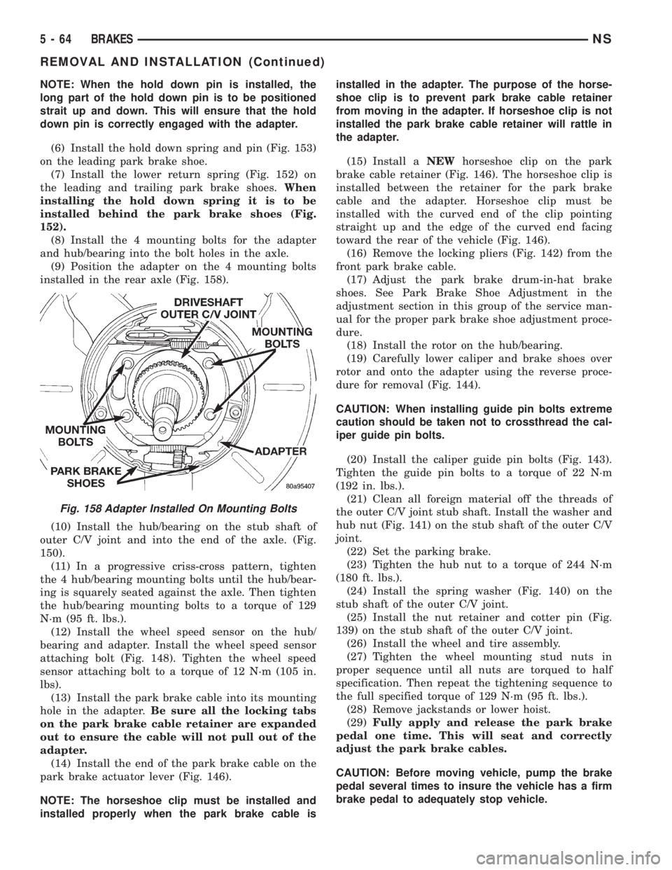
(8) Install the 4 mounting bolts for the adapter
and hub/bearing into the bolt holes in the axle.
(9) Position the adapter on the 4 mounting bolts
installed in the rear axle (Fig. 158).
(10) Install the hub/bearing on the stub shaft of
outer C/V joint and into the end of the axle. (Fig.
150).
(11) In a progressive criss-cross pattern, tighten
the 4 hub/bearing mounting bolts until the hub/bear-
ing is squarely seated against the axle. Then tighten
the hub/bearing mounting bolts to a torque of 129
N´m (95 ft. lbs.).
(12) Install the wheel speed sensor on the hub/
bearing and adapter. Install the wheel speed sensor
attaching bolt (Fig. 148). Tighten the wheel speed
sensor attaching bolt to a torque of 12 N´m (105 in.
lbs).
(13) Install the park brake cable into its mounting
hole in the adapter.Be sure all the locking tabs
on the park brake cable retainer are expanded
out to ensure the cable will not pull out of the
adapter.
(14) Install the end of the park brake cable on the
park brake actuator lever (Fig. 146).
NOTE: The horseshoe clip must be installed and
installed properly when the park brake cable isinstalled in the adapter. The purpose of the horse-
shoe clip is to prevent park brake cable retainer
from moving in the adapter. If horseshoe clip is not
installed the park brake cable retainer will rattle in
the adapter.
(15) Install aNEWhorseshoe clip on the park
brake cable retainer (Fig. 146). The horseshoe clip is
installed between the retainer for the park brake
cable and the adapter. Horseshoe clip must be
installed with the curved end of the clip pointing
straight up and the edge of the curved end facing
toward the rear of the vehicle (Fig. 146).
(16) Remove the locking pliers (Fig. 142) from the
front park brake cable.
(17) Adjust the park brake drum-in-hat brake
shoes. See Park Brake Shoe Adjustment in the
adjustment section in this group of the service man-
ual for the proper park brake shoe adjustment proce-
dure.
(18) Install the rotor on the hub/bearing.
(19) Carefully lower caliper and brake shoes over
rotor and onto the adapter using the reverse proce-
dure for removal (Fig. 144).
CAUTION: When installing guide pin bolts extreme
caution should be taken not to crossthread the cal-
iper guide pin bolts.
(20) Install the caliper guide pin bolts (Fig. 143).
Tighten the guide pin bolts to a torque of 22 N´m
(192 in. lbs.).
(21) Clean all foreign material off the threads of
the outer C/V joint stub shaft. Install the washer and
hub nut (Fig. 141) on the stub shaft of the outer C/V
joint.
(22) Set the parking brake.
(23) Tighten the hub nut to a torque of 244 N´m
(180 ft. lbs.).
(24) Install the spring washer (Fig. 140) on the
stub shaft of the outer C/V joint.
(25) Install the nut retainer and cotter pin (Fig.
139) on the stub shaft of the outer C/V joint.
(26) Install the wheel and tire assembly.
(27) Tighten the wheel mounting stud nuts in
proper sequence until all nuts are torqued to half
specification. Then repeat the tightening sequence to
the full specified torque of 129 N´m (95 ft. lbs.).
(28) Remove jackstands or lower hoist.
(29)Fully apply and release the park brake
pedal one time. This will seat and correctly
adjust the park brake cables.
CAUTION: Before moving vehicle, pump the brake
pedal several times to insure the vehicle has a firm
brake pedal to adequately stop vehicle.
Fig. 158 Adapter Installed On Mounting Bolts
5 - 64 BRAKESNS
REMOVAL AND INSTALLATION (Continued)
Page 193 of 1938
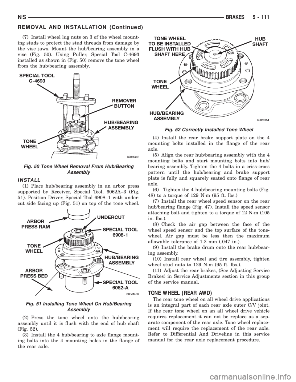
(7) Install wheel lug nuts on 3 of the wheel mount-
ing studs to protect the stud threads from damage by
the vise jaws. Mount the hub/bearing assembly in a
vise (Fig. 50). Using Puller, Special Tool C-4693
installed as shown in (Fig. 50) remove the tone wheel
from the hub/bearing assembly.
INSTALL
(1) Place hub/bearing assembly in an arbor press
supported by Receiver, Special Tool, 6062A±3 (Fig.
51). Position Driver, Special Tool 6908±1 with under-
cut side facing up (Fig. 51) on top of the tone wheel.
(2) Press the tone wheel onto the hub/bearing
assembly until it is flush with the end of hub shaft
(Fig. 52).
(3) Install the 4 hub/bearing to axle flange mount-
ing bolts into the 4 mounting holes in the flange of
the rear axle.(4) Install the rear brake support plate on the 4
mounting bolts installed in the flange of the rear
axle.
(5) Align the rear hub/bearing assembly with the 4
mounting bolts and start mounting bolts into hub/
bearing assembly. Tighten the 4 bolts in a criss-cross
pattern until the hub/bearing and brake support
plate is fully and squarely seated onto flange of rear
axle.
(6) Tighten the 4 hub/bearing mounting bolts (Fig.
48) to a torque of 129 N´m (95 ft. lbs.)
(7) Install the rear wheel speed sensor on the rear
hub/bearing flange (Fig. 47). Install the speed sensor
attaching bolt and tighten to a torque of 12 N´m (105
in. lbs.).
(8) Check the air gap between the face of the
wheel speed sensor and the top surface of the tone-
wheel. Air gap must be less then the maximum
allowable tolerance of 1.2 mm (.047 in.).
(9) Install the brake drum onto the rear hub/bear-
ing assembly.
(10) Install rear wheel and tire assembly, tighten
wheel stud nuts to 129 N´m (95 ft. lbs.).
(11) Adjust the rear brakes, (See Adjusting Service
Brakes) in Service Adjustments section in this group
of the service manual.
TONE WHEEL (REAR AWD)
The rear tone wheel on all wheel drive applications
is an integral part of each rear axle outer C/V joint.
If the rear tone wheel on an all wheel drive vehicle
requires replacement it can not be replace as a sep-
arate component of the rear axle. Tone wheel replace-
ment will require the replacement of the rear axle.
Refer to Differential And Driveline in this service
manual for the rear axle replacement procedure.
Fig. 50 Tone Wheel Removal From Hub/Bearing
Assembly
Fig. 51 Installing Tone Wheel On Hub/Bearing
Assembly
Fig. 52 Correctly Installed Tone Wheel
NSBRAKES 5 - 111
REMOVAL AND INSTALLATION (Continued)
Page 211 of 1938
INSTALLATION
1. Position the slave cylinder assembly to the tran-
saxle deck and secure with the nut and washer
assemblies (2) and tighten to specifications (Fig. 14).
2. Make sure the slave cylinder pushrod is prop-
erly seated in the cup end of the clutch release lever.
3. Connect the quick connect coupling. Refer to the
ªQuick Connect Couplingº removal and installation
procedure in this section.
MODULAR CLUTCH ASSEMBLY (2.0L AND 2.4L
GASOLINE)
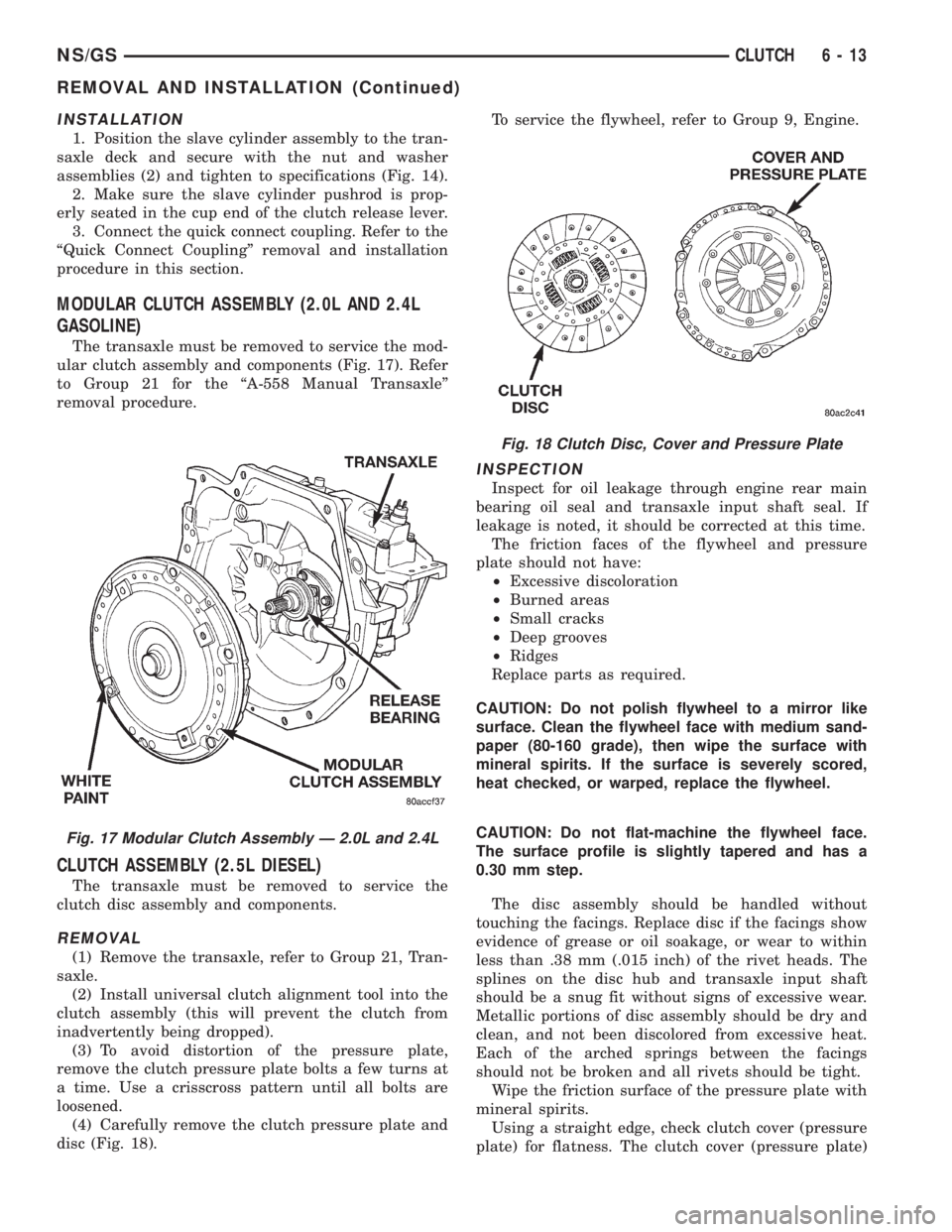
The transaxle must be removed to service the mod-
ular clutch assembly and components (Fig. 17). Refer
to Group 21 for the ªA-558 Manual Transaxleº
removal procedure.
CLUTCH ASSEMBLY (2.5L DIESEL)
The transaxle must be removed to service the
clutch disc assembly and components.
REMOVAL
(1) Remove the transaxle, refer to Group 21, Tran-
saxle.
(2) Install universal clutch alignment tool into the
clutch assembly (this will prevent the clutch from
inadvertently being dropped).
(3) To avoid distortion of the pressure plate,
remove the clutch pressure plate bolts a few turns at
a time. Use a crisscross pattern until all bolts are
loosened.
(4) Carefully remove the clutch pressure plate and
disc (Fig. 18).To service the flywheel, refer to Group 9, Engine.
INSPECTION
Inspect for oil leakage through engine rear main
bearing oil seal and transaxle input shaft seal. If
leakage is noted, it should be corrected at this time.
The friction faces of the flywheel and pressure
plate should not have:
²Excessive discoloration
²Burned areas
²Small cracks
²Deep grooves
²Ridges
Replace parts as required.
CAUTION: Do not polish flywheel to a mirror like
surface. Clean the flywheel face with medium sand-
paper (80-160 grade), then wipe the surface with
mineral spirits. If the surface is severely scored,
heat checked, or warped, replace the flywheel.
CAUTION: Do not flat-machine the flywheel face.
The surface profile is slightly tapered and has a
0.30 mm step.
The disc assembly should be handled without
touching the facings. Replace disc if the facings show
evidence of grease or oil soakage, or wear to within
less than .38 mm (.015 inch) of the rivet heads. The
splines on the disc hub and transaxle input shaft
should be a snug fit without signs of excessive wear.
Metallic portions of disc assembly should be dry and
clean, and not been discolored from excessive heat.
Each of the arched springs between the facings
should not be broken and all rivets should be tight.
Wipe the friction surface of the pressure plate with
mineral spirits.
Using a straight edge, check clutch cover (pressure
plate) for flatness. The clutch cover (pressure plate)
Fig. 17 Modular Clutch Assembly Ð 2.0L and 2.4L
Fig. 18 Clutch Disc, Cover and Pressure Plate
NS/GSCLUTCH 6 - 13
REMOVAL AND INSTALLATION (Continued)
Page 212 of 1938
friction area should be slightly concave, with the
inner diameter 0.02 mm to 0.1 mm (.0008 in. to .0039
in.) below the outer diameter. It should also be free
from discoloration, burned areas, cracks, grooves, or
ridges.
Using a surface plate, test cover for flatness. All
sections around attaching bolt holes should be in con-
tact with surface plate within .015 inch.
The cover should be a snug fit on flywheel dowels.
If the clutch assembly does not meet these require-
ments, it should be replaced.
INSTALLATION
(1) Position the clutch and pressure plate onto the
flywheel.
(2) Insert the universal clutch alignment tool into
the clutch disc.
(3) To avoid distortion of the pressure plate, bolts
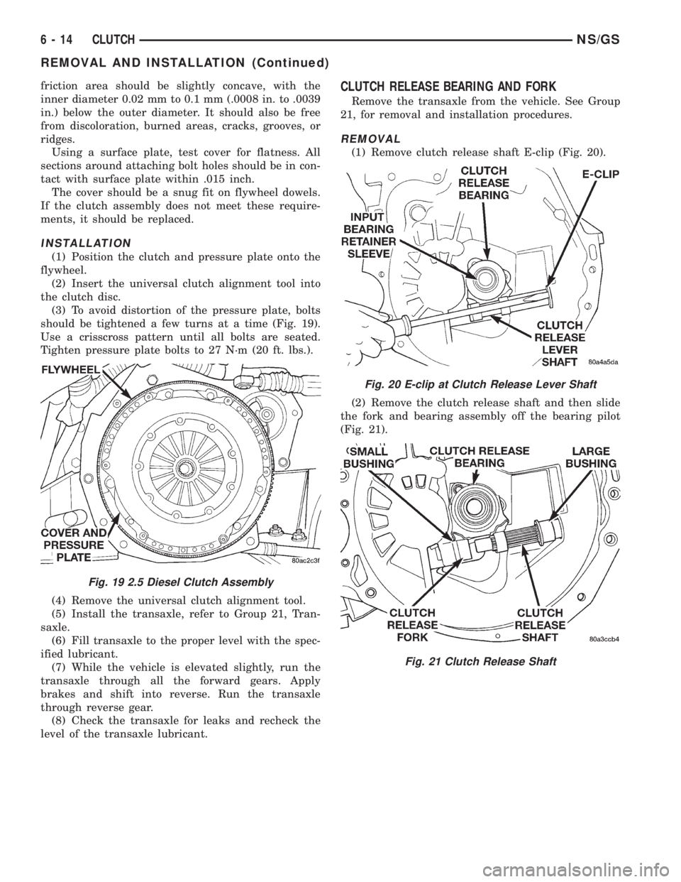
should be tightened a few turns at a time (Fig. 19).
Use a crisscross pattern until all bolts are seated.
Tighten pressure plate bolts to 27 N´m (20 ft. lbs.).
(4) Remove the universal clutch alignment tool.
(5) Install the transaxle, refer to Group 21, Tran-
saxle.
(6) Fill transaxle to the proper level with the spec-
ified lubricant.
(7) While the vehicle is elevated slightly, run the
transaxle through all the forward gears. Apply
brakes and shift into reverse. Run the transaxle
through reverse gear.
(8) Check the transaxle for leaks and recheck the
level of the transaxle lubricant.
CLUTCH RELEASE BEARING AND FORK
Remove the transaxle from the vehicle. See Group
21, for removal and installation procedures.
REMOVAL
(1) Remove clutch release shaft E-clip (Fig. 20).
(2) Remove the clutch release shaft and then slide
the fork and bearing assembly off the bearing pilot
(Fig. 21).
Fig. 19 2.5 Diesel Clutch Assembly
Fig. 20 E-clip at Clutch Release Lever Shaft
Fig. 21 Clutch Release Shaft
6 - 14 CLUTCHNS/GS
REMOVAL AND INSTALLATION (Continued)
Page 1053 of 1938
(5) Test resistance of spark plug cables. Refer to
Group 8D, Ignition System.
(6) Test ignition coils primary and secondary resis-
tance. Replace parts as necessary. Refer to Group 8D,
Ignition System.
(7) Check fuel pump pressure at idle and different
RPM ranges. Refer to Group 14, Fuel System for
Specifications.
(8) The air filter elements should be replaced as
specified in Group 0, Lubrication and Maintenance.
(9) Inspect crankcase ventilation system as out-
lined in Group 25, Emission Control Systems.
(10) Road test vehicle as a final test.
HONING CYLINDER BORES
(1) Used carefully, the cylinder bore resizing hone
C-823 equipped with 220 grit stones, is the best tool
for this job. In addition to deglazing, it will reduce
taper and out-of-round as well as removing light
scuffing, scoring or scratches. Usually a few strokes
will clean up a bore and maintain the required lim-
its.
(2) Deglazing of the cylinder walls may be done
using a cylinder surfacing hone, Tool C-3501,
equipped with 280 grit stones, if the cylinder bore is
straight and round. 20-60 strokes depending on the
bore condition, will be sufficient to provide a satisfac-
tory surface. Inspect cylinder walls after each 20
strokes, using a light honing oil.Do not use engine
or transmission oil, mineral spirits or kerosene.
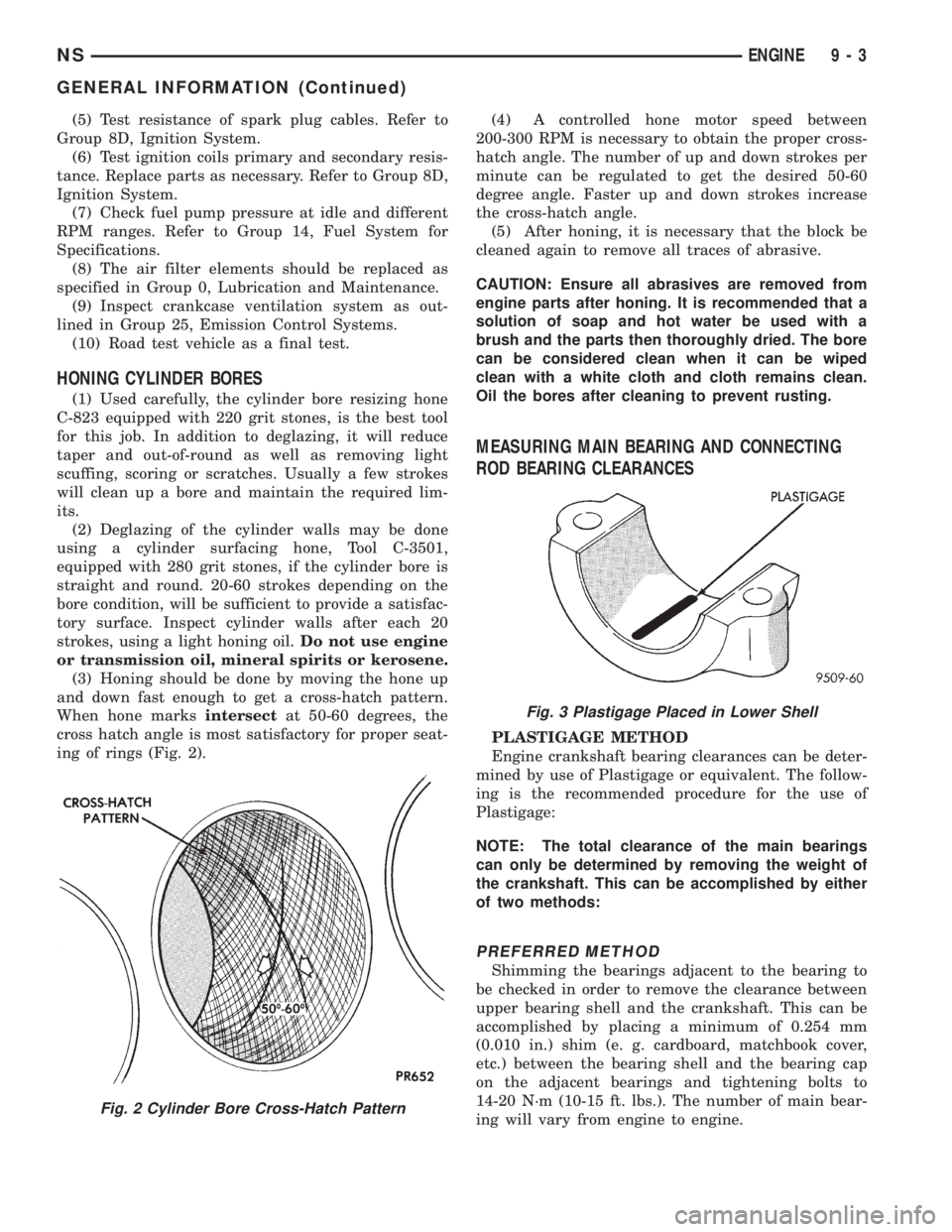
(3) Honing should be done by moving the hone up
and down fast enough to get a cross-hatch pattern.
When hone marksintersectat 50-60 degrees, the
cross hatch angle is most satisfactory for proper seat-
ing of rings (Fig. 2).(4) A controlled hone motor speed between
200-300 RPM is necessary to obtain the proper cross-
hatch angle. The number of up and down strokes per
minute can be regulated to get the desired 50-60
degree angle. Faster up and down strokes increase
the cross-hatch angle.
(5) After honing, it is necessary that the block be
cleaned again to remove all traces of abrasive.
CAUTION: Ensure all abrasives are removed from
engine parts after honing. It is recommended that a
solution of soap and hot water be used with a
brush and the parts then thoroughly dried. The bore
can be considered clean when it can be wiped
clean with a white cloth and cloth remains clean.
Oil the bores after cleaning to prevent rusting.
MEASURING MAIN BEARING AND CONNECTING
ROD BEARING CLEARANCES
PLASTIGAGE METHOD
Engine crankshaft bearing clearances can be deter-
mined by use of Plastigage or equivalent. The follow-
ing is the recommended procedure for the use of
Plastigage:
NOTE: The total clearance of the main bearings
can only be determined by removing the weight of
the crankshaft. This can be accomplished by either
of two methods:
PREFERRED METHOD
Shimming the bearings adjacent to the bearing to
be checked in order to remove the clearance between
upper bearing shell and the crankshaft. This can be
accomplished by placing a minimum of 0.254 mm
(0.010 in.) shim (e. g. cardboard, matchbook cover,
etc.) between the bearing shell and the bearing cap
on the adjacent bearings and tightening bolts to
14-20 N´m (10-15 ft. lbs.). The number of main bear-
ing will vary from engine to engine.
Fig. 2 Cylinder Bore Cross-Hatch Pattern
Fig. 3 Plastigage Placed in Lower Shell
NSENGINE 9 - 3
GENERAL INFORMATION (Continued)