odometer CHRYSLER VOYAGER 1996 Service Manual
[x] Cancel search | Manufacturer: CHRYSLER, Model Year: 1996, Model line: VOYAGER, Model: CHRYSLER VOYAGER 1996Pages: 1938, PDF Size: 55.84 MB
Page 28 of 1938
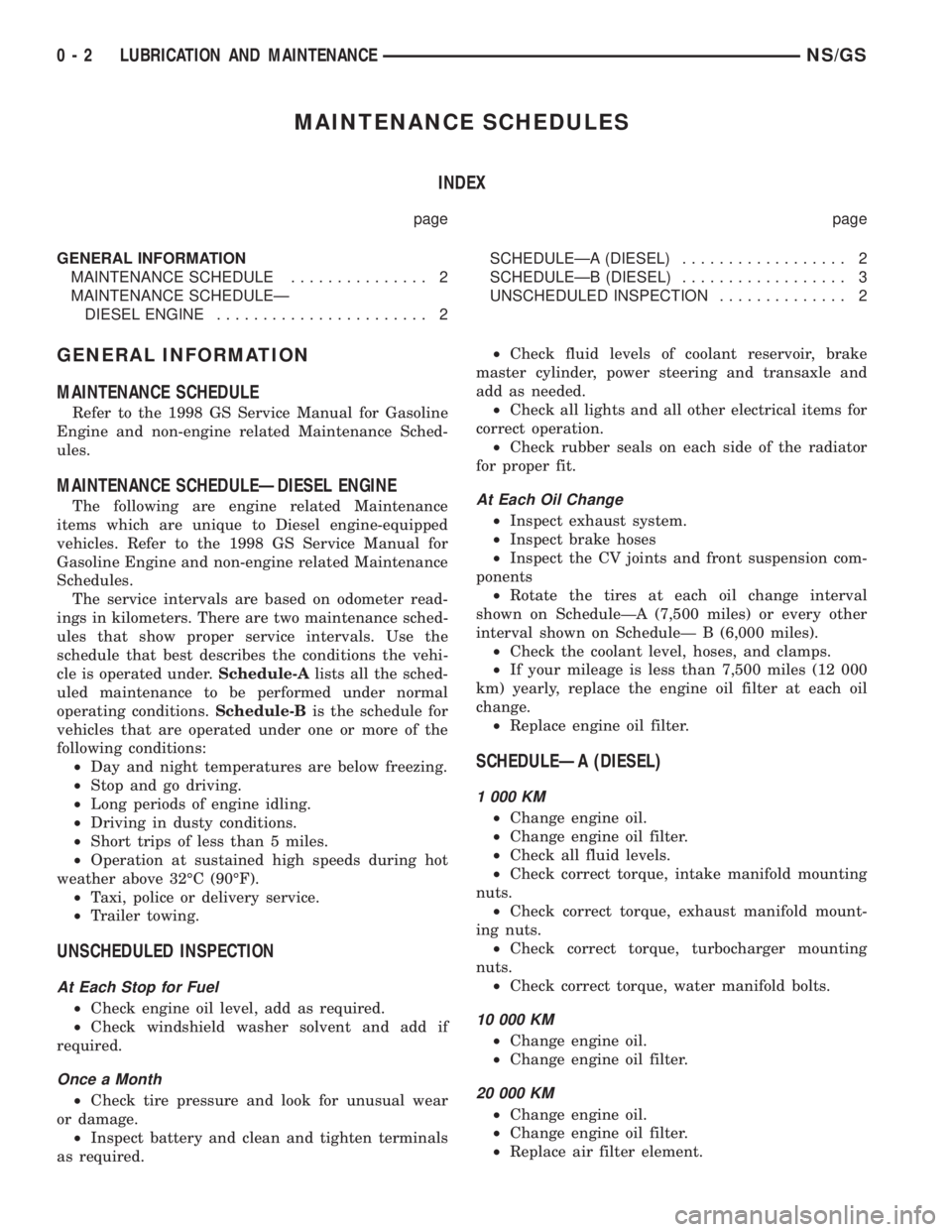
MAINTENANCE SCHEDULES
INDEX
page page
GENERAL INFORMATION
MAINTENANCE SCHEDULE............... 2
MAINTENANCE SCHEDULEÐ
DIESEL ENGINE....................... 2SCHEDULEÐA (DIESEL).................. 2
SCHEDULEÐB (DIESEL).................. 3
UNSCHEDULED INSPECTION.............. 2
GENERAL INFORMATION
MAINTENANCE SCHEDULE
Refer to the 1998 GS Service Manual for Gasoline
Engine and non-engine related Maintenance Sched-
ules.
MAINTENANCE SCHEDULEÐDIESEL ENGINE
The following are engine related Maintenance
items which are unique to Diesel engine-equipped
vehicles. Refer to the 1998 GS Service Manual for
Gasoline Engine and non-engine related Maintenance
Schedules.
The service intervals are based on odometer read-
ings in kilometers. There are two maintenance sched-
ules that show proper service intervals. Use the
schedule that best describes the conditions the vehi-
cle is operated under.Schedule-Alists all the sched-
uled maintenance to be performed under normal
operating conditions.Schedule-Bis the schedule for
vehicles that are operated under one or more of the
following conditions:
²Day and night temperatures are below freezing.
²Stop and go driving.
²Long periods of engine idling.
²Driving in dusty conditions.
²Short trips of less than 5 miles.
²Operation at sustained high speeds during hot
weather above 32ÉC (90ÉF).
²Taxi, police or delivery service.
²Trailer towing.
UNSCHEDULED INSPECTION
At Each Stop for Fuel
²Check engine oil level, add as required.
²Check windshield washer solvent and add if
required.
Once a Month
²Check tire pressure and look for unusual wear
or damage.
²Inspect battery and clean and tighten terminals
as required.²Check fluid levels of coolant reservoir, brake
master cylinder, power steering and transaxle and
add as needed.
²Check all lights and all other electrical items for
correct operation.
²Check rubber seals on each side of the radiator
for proper fit.
At Each Oil Change
²Inspect exhaust system.
²Inspect brake hoses
²Inspect the CV joints and front suspension com-
ponents
²Rotate the tires at each oil change interval
shown on ScheduleÐA (7,500 miles) or every other
interval shown on ScheduleÐ B (6,000 miles).
²Check the coolant level, hoses, and clamps.
²If your mileage is less than 7,500 miles (12 000
km) yearly, replace the engine oil filter at each oil
change.
²Replace engine oil filter.
SCHEDULEÐA (DIESEL)
1 000 KM
²Change engine oil.
²Change engine oil filter.
²Check all fluid levels.
²Check correct torque, intake manifold mounting
nuts.
²Check correct torque, exhaust manifold mount-
ing nuts.
²Check correct torque, turbocharger mounting
nuts.
²Check correct torque, water manifold bolts.
10 000 KM
²Change engine oil.
²Change engine oil filter.
20 000 KM
²Change engine oil.
²Change engine oil filter.
²Replace air filter element.
0 - 2 LUBRICATION AND MAINTENANCENS/GS
Page 337 of 1938
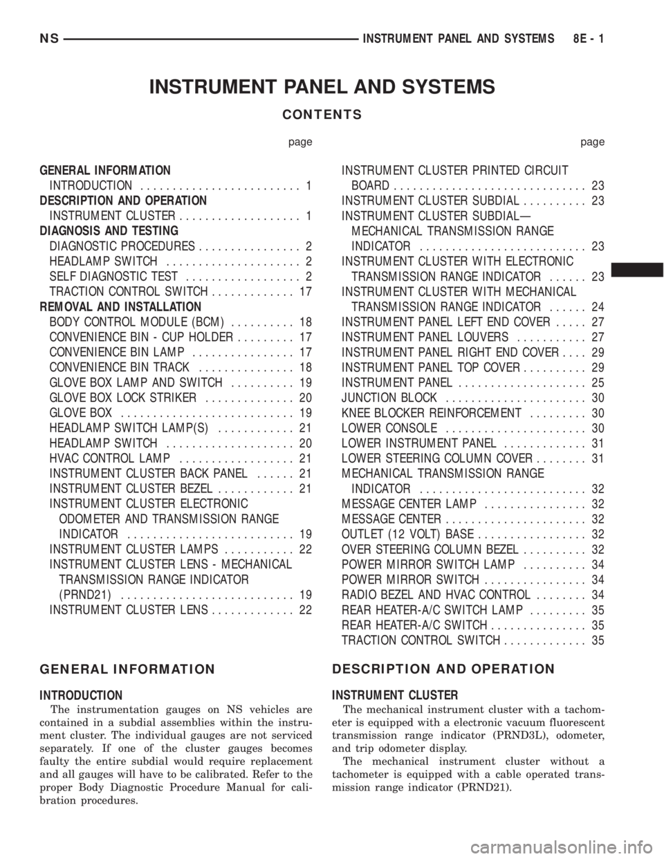
INSTRUMENT PANEL AND SYSTEMS
CONTENTS
page page
GENERAL INFORMATION
INTRODUCTION......................... 1
DESCRIPTION AND OPERATION
INSTRUMENT CLUSTER................... 1
DIAGNOSIS AND TESTING
DIAGNOSTIC PROCEDURES................ 2
HEADLAMP SWITCH..................... 2
SELF DIAGNOSTIC TEST.................. 2
TRACTION CONTROL SWITCH............. 17
REMOVAL AND INSTALLATION
BODY CONTROL MODULE (BCM).......... 18
CONVENIENCE BIN - CUP HOLDER......... 17
CONVENIENCE BIN LAMP................ 17
CONVENIENCE BIN TRACK............... 18
GLOVE BOX LAMP AND SWITCH.......... 19
GLOVE BOX LOCK STRIKER.............. 20
GLOVE BOX........................... 19
HEADLAMP SWITCH LAMP(S)............ 21
HEADLAMP SWITCH.................... 20
HVAC CONTROL LAMP.................. 21
INSTRUMENT CLUSTER BACK PANEL...... 21
INSTRUMENT CLUSTER BEZEL............ 21
INSTRUMENT CLUSTER ELECTRONIC
ODOMETER AND TRANSMISSION RANGE
INDICATOR.......................... 19
INSTRUMENT CLUSTER LAMPS........... 22
INSTRUMENT CLUSTER LENS - MECHANICAL
TRANSMISSION RANGE INDICATOR
(PRND21)........................... 19
INSTRUMENT CLUSTER LENS............. 22INSTRUMENT CLUSTER PRINTED CIRCUIT
BOARD.............................. 23
INSTRUMENT CLUSTER SUBDIAL.......... 23
INSTRUMENT CLUSTER SUBDIALÐ
MECHANICAL TRANSMISSION RANGE
INDICATOR.......................... 23
INSTRUMENT CLUSTER WITH ELECTRONIC
TRANSMISSION RANGE INDICATOR...... 23
INSTRUMENT CLUSTER WITH MECHANICAL
TRANSMISSION RANGE INDICATOR...... 24
INSTRUMENT PANEL LEFT END COVER..... 27
INSTRUMENT PANEL LOUVERS........... 27
INSTRUMENT PANEL RIGHT END COVER.... 29
INSTRUMENT PANEL TOP COVER.......... 29
INSTRUMENT PANEL.................... 25
JUNCTION BLOCK...................... 30
KNEE BLOCKER REINFORCEMENT......... 30
LOWER CONSOLE...................... 30
LOWER INSTRUMENT PANEL............. 31
LOWER STEERING COLUMN COVER........ 31
MECHANICAL TRANSMISSION RANGE
INDICATOR.......................... 32
MESSAGE CENTER LAMP................ 32
MESSAGE CENTER...................... 32
OUTLET (12 VOLT) BASE................. 32
OVER STEERING COLUMN BEZEL.......... 32
POWER MIRROR SWITCH LAMP.......... 34
POWER MIRROR SWITCH................ 34
RADIO BEZEL AND HVAC CONTROL........ 34
REAR HEATER-A/C SWITCH LAMP......... 35
REAR HEATER-A/C SWITCH............... 35
TRACTION CONTROL SWITCH............. 35
GENERAL INFORMATION
INTRODUCTION
The instrumentation gauges on NS vehicles are
contained in a subdial assemblies within the instru-
ment cluster. The individual gauges are not serviced
separately. If one of the cluster gauges becomes
faulty the entire subdial would require replacement
and all gauges will have to be calibrated. Refer to the
proper Body Diagnostic Procedure Manual for cali-
bration procedures.
DESCRIPTION AND OPERATION
INSTRUMENT CLUSTER
The mechanical instrument cluster with a tachom-
eter is equipped with a electronic vacuum fluorescent
transmission range indicator (PRND3L), odometer,
and trip odometer display.
The mechanical instrument cluster without a
tachometer is equipped with a cable operated trans-
mission range indicator (PRND21).
NSINSTRUMENT PANEL AND SYSTEMS 8E - 1
Page 338 of 1938
The instrument cluster is equipped with the follow-
ing warning lamps.
²Lift Gate Ajar
²Low Fuel Level
²Low Windshield Washer Fluid Level
²Cruise
²Battery Voltage
²Fasten Seat Belt
²Door Ajar
DIAGNOSIS AND TESTING
DIAGNOSTIC PROCEDURES
NS vehicle instrument clusters are equipped with a
self diagnostic test feature to help identify electronic
problems. Prior to any test, perform Self Diagnostic
Test. The self diagnostic system monitors the CCD
bus messages. If an electronic problem occurs, a
Diagnostic Trouble Code (DTC) will be displayed in
the odometer window of the cluster.
The following CCD bus messages are continuously
monitored by the diagnostic system:
²Body Control Module
²Powertrain Control Module
²Transmission Control Module, if equipped
HEADLAMP SWITCH
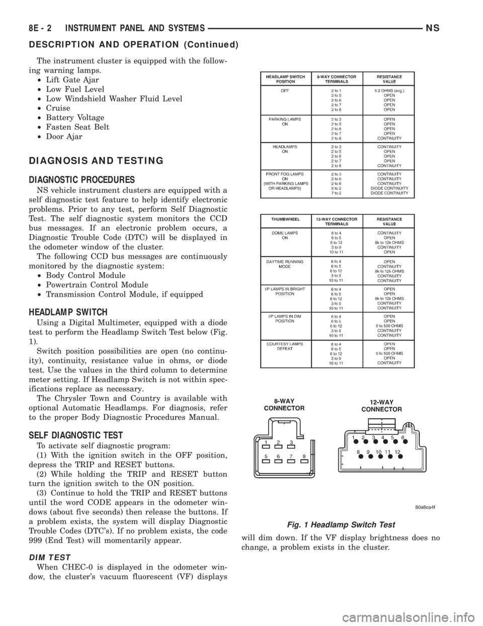
Using a Digital Multimeter, equipped with a diode
test to perform the Headlamp Switch Test below (Fig.
1).
Switch position possibilities are open (no continu-
ity), continuity, resistance value in ohms, or diode
test. Use the values in the third column to determine
meter setting. If Headlamp Switch is not within spec-
ifications replace as necessary.
The Chrysler Town and Country is available with
optional Automatic Headlamps. For diagnosis, refer
to the proper Body Diagnostic Procedures Manual.
SELF DIAGNOSTIC TEST
To activate self diagnostic program:
(1) With the ignition switch in the OFF position,
depress the TRIP and RESET buttons.
(2) While holding the TRIP and RESET button
turn the ignition switch to the ON position.
(3) Continue to hold the TRIP and RESET buttons
until the word CODE appears in the odometer win-
dows (about five seconds) then release the buttons. If
a problem exists, the system will display Diagnostic
Trouble Codes (DTC's). If no problem exists, the code
999 (End Test) will momentarily appear.
DIM TEST
When CHEC-0 is displayed in the odometer win-
dow, the cluster's vacuum fluorescent (VF) displayswill dim down. If the VF display brightness does no
change, a problem exists in the cluster.
Fig. 1 Headlamp Switch Test
8E - 2 INSTRUMENT PANEL AND SYSTEMSNS
DESCRIPTION AND OPERATION (Continued)
Page 339 of 1938
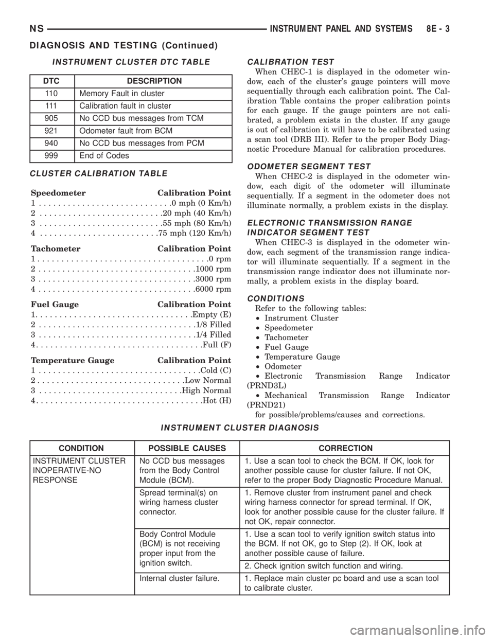
CLUSTER CALIBRATION TABLE
Speedometer Calibration Point
1 ............................0mph(0Km/h)
2 ..........................20mph(40Km/h)
3 ..........................55mph(80Km/h)
4 .........................75mph(120 Km/h)
Tachometer Calibration Point
1....................................0rpm
2 .................................1000 rpm
3 .................................3000 rpm
4 .................................6000 rpm
Fuel Gauge Calibration Point
1.................................Empty (E)
2 .................................1/8 Filled
3 .................................1/4 Filled
4...................................Full (F)
Temperature Gauge Calibration Point
1 ..................................Cold (C)
2...............................Low Normal
3 ..............................High Normal
4...................................Hot (H)
CALIBRATION TEST
When CHEC-1 is displayed in the odometer win-
dow, each of the cluster's gauge pointers will move
sequentially through each calibration point. The Cal-
ibration Table contains the proper calibration points
for each gauge. If the gauge pointers are not cali-
brated, a problem exists in the cluster. If any gauge
is out of calibration it will have to be calibrated using
a scan tool (DRB III). Refer to the proper Body Diag-
nostic Procedure Manual for calibration procedures.
ODOMETER SEGMENT TEST
When CHEC-2 is displayed in the odometer win-
dow, each digit of the odometer will illuminate
sequentially. If a segment in the odometer does not
illuminate normally, a problem exists in the display.
ELECTRONIC TRANSMISSION RANGE
INDICATOR SEGMENT TEST
When CHEC-3 is displayed in the odometer win-
dow, each segment of the transmission range indica-
tor will illuminate sequentially. If a segment in the
transmission range indicator does not illuminate nor-
mally, a problem exists in the display board.
CONDITIONS
Refer to the following tables:
²Instrument Cluster
²Speedometer
²Tachometer
²Fuel Gauge
²Temperature Gauge
²Odometer
²Electronic Transmission Range Indicator
(PRND3L)
²Mechanical Transmission Range Indicator
(PRND21)
for possible/problems/causes and corrections.
INSTRUMENT CLUSTER DTC TABLE
DTC DESCRIPTION
110 Memory Fault in cluster
111 Calibration fault in cluster
905 No CCD bus messages from TCM
921 Odometer fault from BCM
940 No CCD bus messages from PCM
999 End of Codes
INSTRUMENT CLUSTER DIAGNOSIS
CONDITION POSSIBLE CAUSES CORRECTION
INSTRUMENT CLUSTER
INOPERATIVE-NO
RESPONSENo CCD bus messages
from the Body Control
Module (BCM).1. Use a scan tool to check the BCM. If OK, look for
another possible cause for cluster failure. If not OK,
refer to the proper Body Diagnostic Procedure Manual.
Spread terminal(s) on
wiring harness cluster
connector.1. Remove cluster from instrument panel and check
wiring harness connector for spread terminal. If OK,
look for another possible cause for the cluster failure. If
not OK, repair connector.
Body Control Module
(BCM) is not receiving
proper input from the
ignition switch.1. Use a scan tool to verify ignition switch status into
the BCM. If not OK, go to Step (2). If OK, look at
another possible cause of failure.
2. Check ignition switch function and wiring.
Internal cluster failure. 1. Replace main cluster pc board and use a scan tool
to calibrate cluster.
NSINSTRUMENT PANEL AND SYSTEMS 8E - 3
DIAGNOSIS AND TESTING (Continued)
Page 340 of 1938
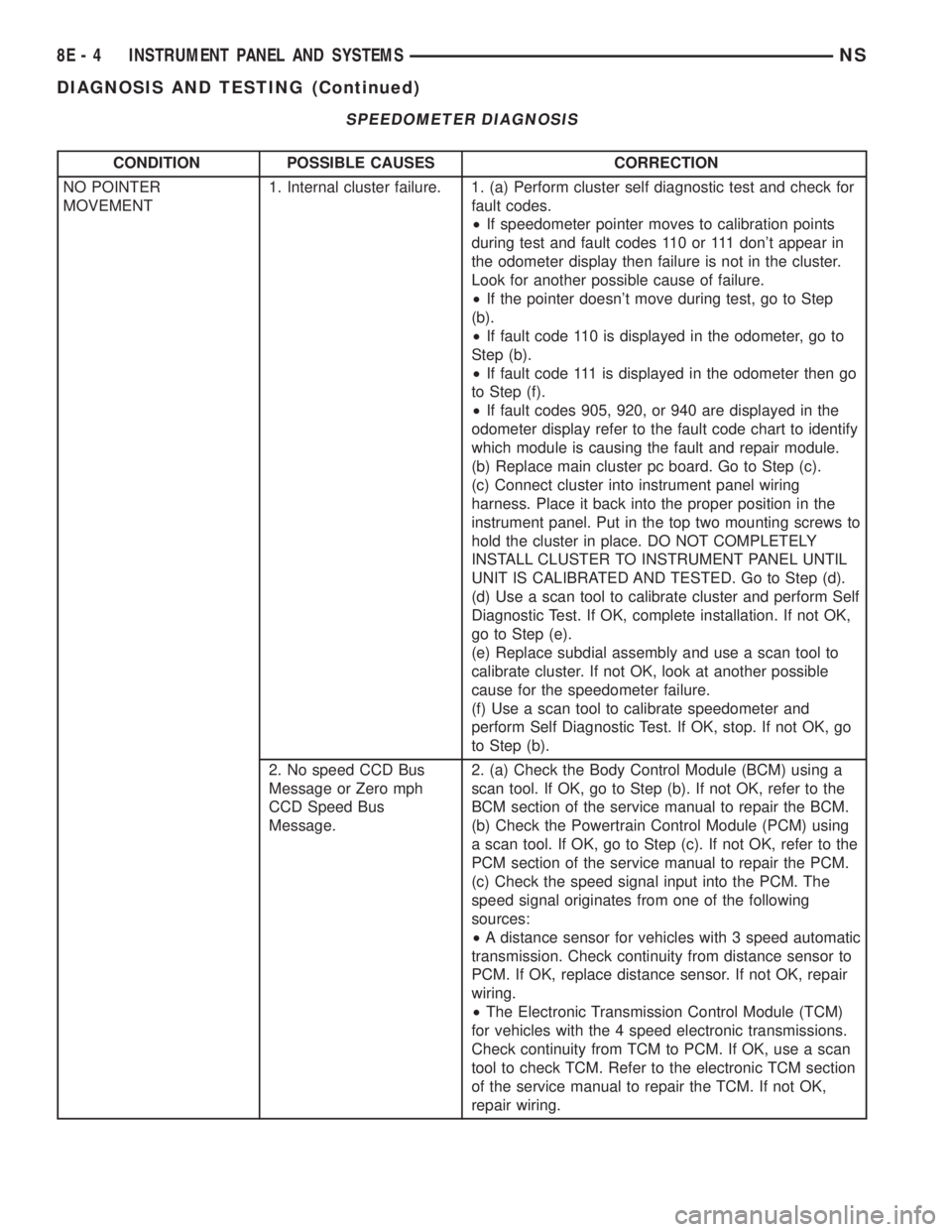
SPEEDOMETER DIAGNOSIS
CONDITION POSSIBLE CAUSES CORRECTION
NO POINTER
MOVEMENT1. Internal cluster failure. 1. (a) Perform cluster self diagnostic test and check for
fault codes.
²If speedometer pointer moves to calibration points
during test and fault codes 110 or 111 don't appear in
the odometer display then failure is not in the cluster.
Look for another possible cause of failure.
²If the pointer doesn't move during test, go to Step
(b).
²If fault code 110 is displayed in the odometer, go to
Step (b).
²If fault code 111 is displayed in the odometer then go
to Step (f).
²If fault codes 905, 920, or 940 are displayed in the
odometer display refer to the fault code chart to identify
which module is causing the fault and repair module.
(b) Replace main cluster pc board. Go to Step (c).
(c) Connect cluster into instrument panel wiring
harness. Place it back into the proper position in the
instrument panel. Put in the top two mounting screws to
hold the cluster in place. DO NOT COMPLETELY
INSTALL CLUSTER TO INSTRUMENT PANEL UNTIL
UNIT IS CALIBRATED AND TESTED. Go to Step (d).
(d) Use a scan tool to calibrate cluster and perform Self
Diagnostic Test. If OK, complete installation. If not OK,
go to Step (e).
(e) Replace subdial assembly and use a scan tool to
calibrate cluster. If not OK, look at another possible
cause for the speedometer failure.
(f) Use a scan tool to calibrate speedometer and
perform Self Diagnostic Test. If OK, stop. If not OK, go
to Step (b).
2. No speed CCD Bus
Message or Zero mph
CCD Speed Bus
Message.2. (a) Check the Body Control Module (BCM) using a
scan tool. If OK, go to Step (b). If not OK, refer to the
BCM section of the service manual to repair the BCM.
(b) Check the Powertrain Control Module (PCM) using
a scan tool. If OK, go to Step (c). If not OK, refer to the
PCM section of the service manual to repair the PCM.
(c) Check the speed signal input into the PCM. The
speed signal originates from one of the following
sources:
²A distance sensor for vehicles with 3 speed automatic
transmission. Check continuity from distance sensor to
PCM. If OK, replace distance sensor. If not OK, repair
wiring.
²The Electronic Transmission Control Module (TCM)
for vehicles with the 4 speed electronic transmissions.
Check continuity from TCM to PCM. If OK, use a scan
tool to check TCM. Refer to the electronic TCM section
of the service manual to repair the TCM. If not OK,
repair wiring.
8E - 4 INSTRUMENT PANEL AND SYSTEMSNS
DIAGNOSIS AND TESTING (Continued)
Page 341 of 1938
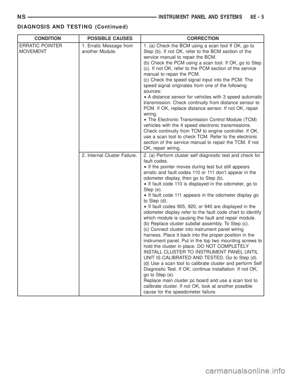
CONDITION POSSIBLE CAUSES CORRECTION
ERRATIC POINTER
MOVEMENT1. Erratic Message from
another Module.1. (a) Check the BCM using a scan tool If OK, go to
Step (b). If not OK, refer to the BCM section of the
service manual to repair the BCM.
(b) Check the PCM using a scan tool. If OK, go to Step
(c). If not OK, refer to the PCM section of the service
manual to repair the PCM.
(c) Check the speed signal input into the PCM. The
speed signal originates from one of the following
sources:
²A distance sensor for vehicles with 3 speed automatic
transmission. Check continuity from distance sensor to
PCM. If OK, replace distance sensor. If not OK, repair
wiring.
²The Electronic Transmission Control Module (TCM)
vehicles with the 4 speed electronic transmissions.
Check continuity from TCM to engine controller. If OK,
use a scan tool to check TCM. Refer to the electronic
section of the service manual to repair the TCM. If not
OK, repair wiring.
2. Internal Cluster Failure. 2. (a) Perform cluster self diagnostic test and check for
fault codes.
²If the pointer moves during test but still appears
erratic and fault codes 110 or 111 don't appear in the
odometer display, then go to Step (b).
²If fault code 110 is displayed in the odometer, go to
Step (e).
²If fault code 111 appears in the odometer display go
to Step (d).
²If fault codes 905, 920, or 940 are displayed in the
odometer display refer to the fault code chart to identify
which module is causing the fault and repair module.
(b) Replace cluster subdial assembly. To Step (c).
(c) Connect cluster into instrument panel wiring
harness. Place it back into the proper position in the
instrument panel. Put in the top two mounting screws to
hold the cluster in place. DO NOT COMPLETELY
INSTALL CLUSTER TO INSTRUMENT PANEL UNTIL
UNIT IS CALIBRATED AND TESTED. Go to Step (d).
(d) Use a scan tool to calibrate cluster and perform Self
Diagnostic Test. If OK, continue installation. If not OK,
go to Step (e).
Replace main cluster pc board and use a scan tool to
calibrate cluster. If not OK, look at another possible
cause for the speedometer failure.
NSINSTRUMENT PANEL AND SYSTEMS 8E - 5
DIAGNOSIS AND TESTING (Continued)
Page 343 of 1938
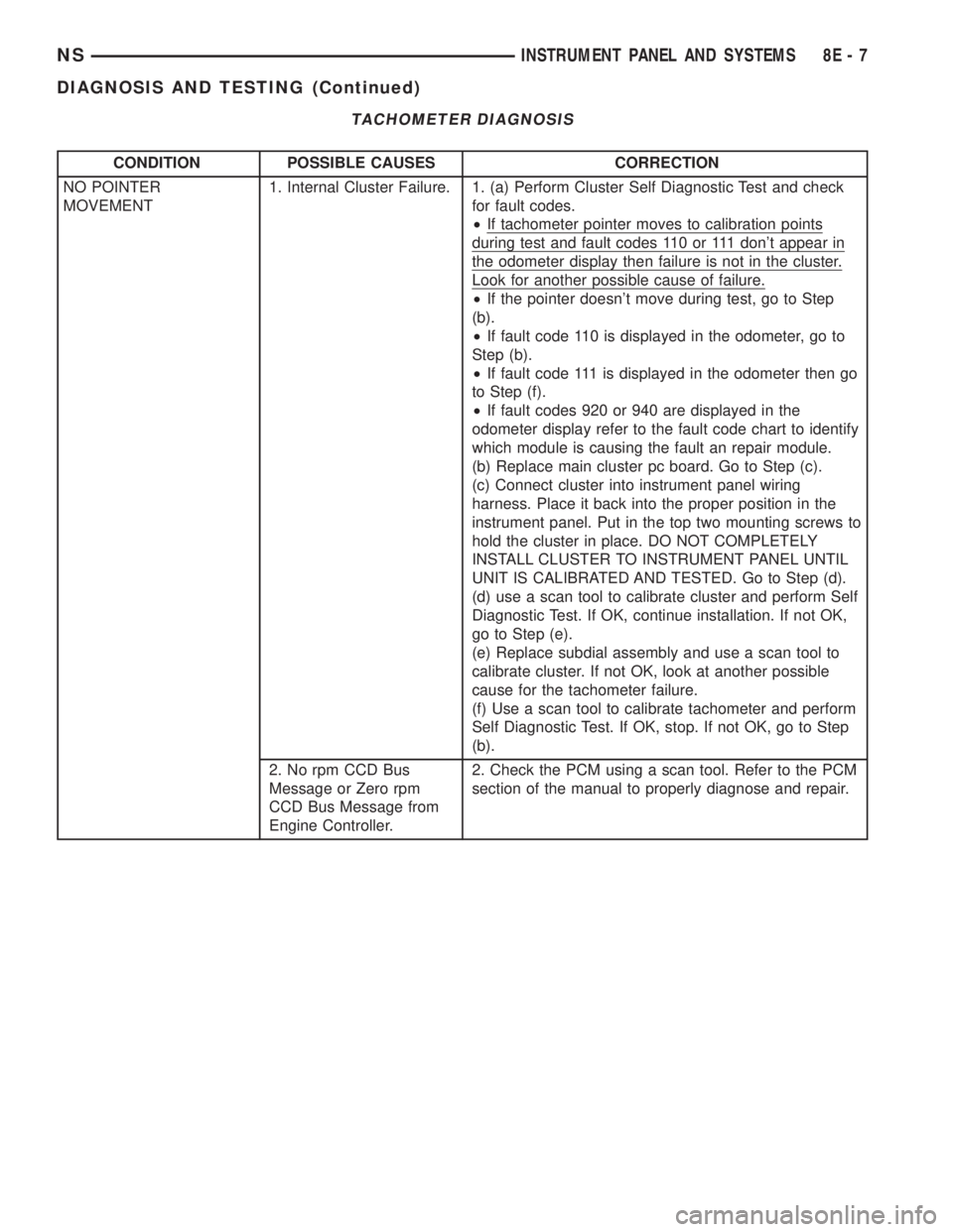
TACHOMETER DIAGNOSIS
CONDITION POSSIBLE CAUSES CORRECTION
NO POINTER
MOVEMENT1. Internal Cluster Failure. 1. (a) Perform Cluster Self Diagnostic Test and check
for fault codes.
²If tachometer pointer moves to calibration points
during test and fault codes 110 or 111 don't appear in
the odometer display then failure is not in the cluster.
Look for another possible cause of failure.
²If the pointer doesn't move during test, go to Step
(b).
²If fault code 110 is displayed in the odometer, go to
Step (b).
²If fault code 111 is displayed in the odometer then go
to Step (f).
²If fault codes 920 or 940 are displayed in the
odometer display refer to the fault code chart to identify
which module is causing the fault an repair module.
(b) Replace main cluster pc board. Go to Step (c).
(c) Connect cluster into instrument panel wiring
harness. Place it back into the proper position in the
instrument panel. Put in the top two mounting screws to
hold the cluster in place. DO NOT COMPLETELY
INSTALL CLUSTER TO INSTRUMENT PANEL UNTIL
UNIT IS CALIBRATED AND TESTED. Go to Step (d).
(d) use a scan tool to calibrate cluster and perform Self
Diagnostic Test. If OK, continue installation. If not OK,
go to Step (e).
(e) Replace subdial assembly and use a scan tool to
calibrate cluster. If not OK, look at another possible
cause for the tachometer failure.
(f) Use a scan tool to calibrate tachometer and perform
Self Diagnostic Test. If OK, stop. If not OK, go to Step
(b).
2. No rpm CCD Bus
Message or Zero rpm
CCD Bus Message from
Engine Controller.2. Check the PCM using a scan tool. Refer to the PCM
section of the manual to properly diagnose and repair.
NSINSTRUMENT PANEL AND SYSTEMS 8E - 7
DIAGNOSIS AND TESTING (Continued)
Page 344 of 1938
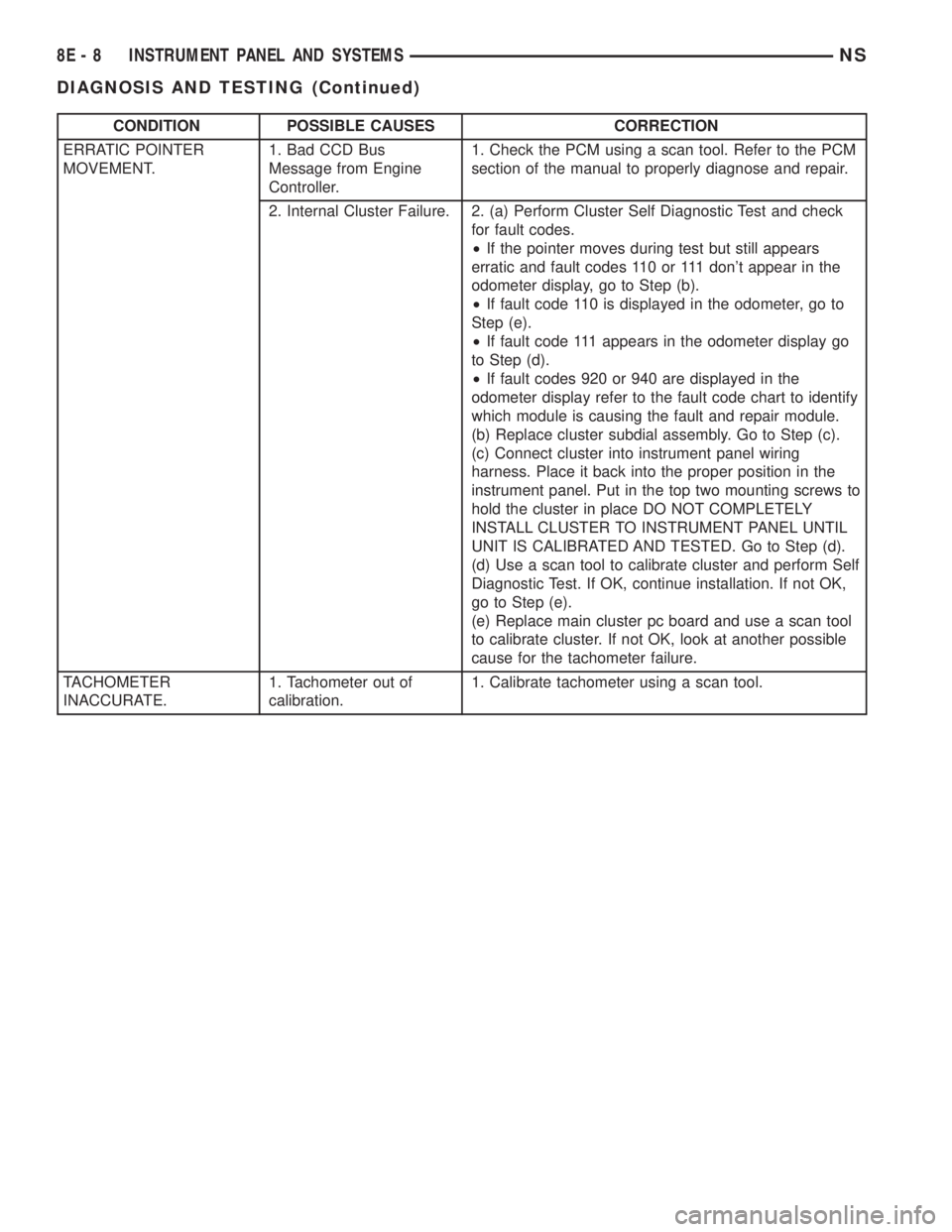
CONDITION POSSIBLE CAUSES CORRECTION
ERRATIC POINTER
MOVEMENT.1. Bad CCD Bus
Message from Engine
Controller.1. Check the PCM using a scan tool. Refer to the PCM
section of the manual to properly diagnose and repair.
2. Internal Cluster Failure. 2. (a) Perform Cluster Self Diagnostic Test and check
for fault codes.
²If the pointer moves during test but still appears
erratic and fault codes 110 or 111 don't appear in the
odometer display, go to Step (b).
²If fault code 110 is displayed in the odometer, go to
Step (e).
²If fault code 111 appears in the odometer display go
to Step (d).
²If fault codes 920 or 940 are displayed in the
odometer display refer to the fault code chart to identify
which module is causing the fault and repair module.
(b) Replace cluster subdial assembly. Go to Step (c).
(c) Connect cluster into instrument panel wiring
harness. Place it back into the proper position in the
instrument panel. Put in the top two mounting screws to
hold the cluster in place DO NOT COMPLETELY
INSTALL CLUSTER TO INSTRUMENT PANEL UNTIL
UNIT IS CALIBRATED AND TESTED. Go to Step (d).
(d) Use a scan tool to calibrate cluster and perform Self
Diagnostic Test. If OK, continue installation. If not OK,
go to Step (e).
(e) Replace main cluster pc board and use a scan tool
to calibrate cluster. If not OK, look at another possible
cause for the tachometer failure.
TACHOMETER
INACCURATE.1. Tachometer out of
calibration.1. Calibrate tachometer using a scan tool.
8E - 8 INSTRUMENT PANEL AND SYSTEMSNS
DIAGNOSIS AND TESTING (Continued)
Page 345 of 1938
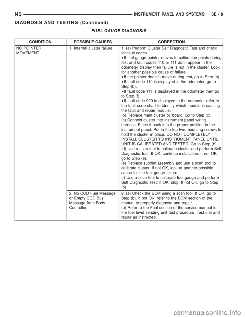
FUEL GAUGE DIAGNOSIS
CONDITION POSSIBLE CAUSES CORRECTION
NO POINTER
MOVEMENT.1. Internal cluster failure. 1. (a) Perform Cluster Self Diagnostic Test and check
for fault codes.
²If fuel gauge pointer moves to calibration points during
test and fault codes 110 or 111 don't appear in the
odometer display then failure is not in the cluster. Look
for another possible cause of failure.
²If the pointer doesn't move during test, go to Step (b).
²If fault code 110 is displayed in the odometer, go to
Step (b).
²If fault code 111 is displayed in the odometer then go
to Step (f).
²If fault code 920 is displayed in the odometer refer to
the fault code chart to identify which module is causing
the fault and repair module.
(b) Replace main cluster pc board. Go to Step (c).
(c) Connect cluster into instrument panel wiring
harness. Place it back into the proper position in the
instrument panel. Put in the top two mounting screws to
hold the cluster in place. DO NOT COMPLETELY
INSTALL CLUSTER TO INSTRUMENT PANEL UNTIL
UNIT IS CALIBRATED AND TESTED. Go to Step (d).
(d) Use a scan tool to calibrate cluster and perform Self
Diagnostic Test. If OK, continue installation. If not OK,
go to Step (e).
(e) Replace subdial assembly and use a scan tool to
calibrate cluster. If not OK, look at another possible
cause for the fuel gauge failure.
(f) Use a scan tool to calibrate fuel gauge and perform
Self Diagnostic Test. If OK, stop. If not OK, go to Step
(b).
2. No CCD Fuel Message
or Empty CCD Bus
Message from Body
Controller.2. (a) Check the BCM using a scan tool. If OK, go to
Step (b). If not OK, refer to the BCM section of the
manual to properly diagnose and repair.
(b) Refer to the Fuel section of the service manual for
the fuel level sending unit test procedure. Test unit and
repair as instructed.
NSINSTRUMENT PANEL AND SYSTEMS 8E - 9
DIAGNOSIS AND TESTING (Continued)
Page 346 of 1938
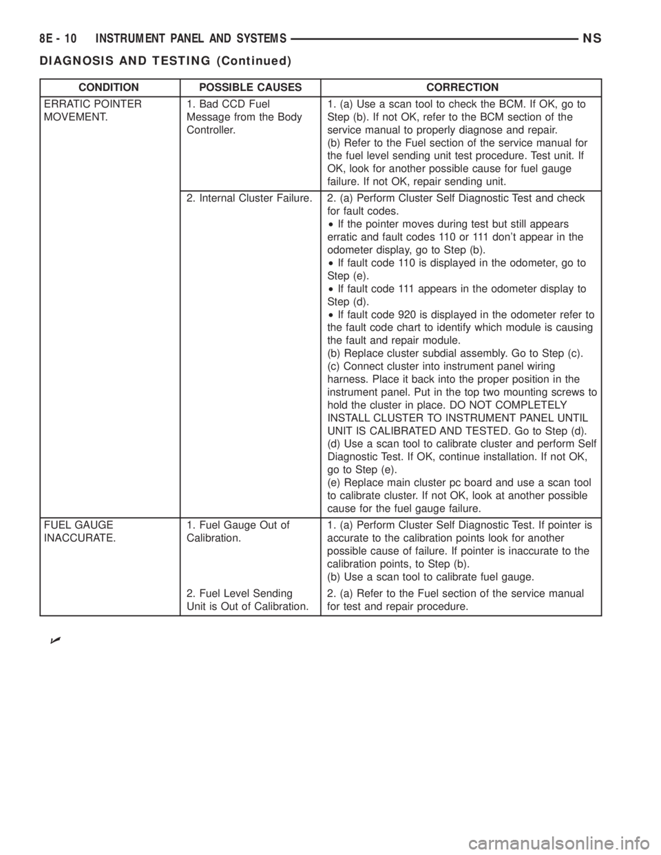
CONDITION POSSIBLE CAUSES CORRECTION
ERRATIC POINTER
MOVEMENT.1. Bad CCD Fuel
Message from the Body
Controller.1. (a) Use a scan tool to check the BCM. If OK, go to
Step (b). If not OK, refer to the BCM section of the
service manual to properly diagnose and repair.
(b) Refer to the Fuel section of the service manual for
the fuel level sending unit test procedure. Test unit. If
OK, look for another possible cause for fuel gauge
failure. If not OK, repair sending unit.
2. Internal Cluster Failure. 2. (a) Perform Cluster Self Diagnostic Test and check
for fault codes.
²If the pointer moves during test but still appears
erratic and fault codes 110 or 111 don't appear in the
odometer display, go to Step (b).
²If fault code 110 is displayed in the odometer, go to
Step (e).
²If fault code 111 appears in the odometer display to
Step (d).
²If fault code 920 is displayed in the odometer refer to
the fault code chart to identify which module is causing
the fault and repair module.
(b) Replace cluster subdial assembly. Go to Step (c).
(c) Connect cluster into instrument panel wiring
harness. Place it back into the proper position in the
instrument panel. Put in the top two mounting screws to
hold the cluster in place. DO NOT COMPLETELY
INSTALL CLUSTER TO INSTRUMENT PANEL UNTIL
UNIT IS CALIBRATED AND TESTED. Go to Step (d).
(d) Use a scan tool to calibrate cluster and perform Self
Diagnostic Test. If OK, continue installation. If not OK,
go to Step (e).
(e) Replace main cluster pc board and use a scan tool
to calibrate cluster. If not OK, look at another possible
cause for the fuel gauge failure.
FUEL GAUGE
INACCURATE.1. Fuel Gauge Out of
Calibration.1. (a) Perform Cluster Self Diagnostic Test. If pointer is
accurate to the calibration points look for another
possible cause of failure. If pointer is inaccurate to the
calibration points, to Step (b).
(b) Use a scan tool to calibrate fuel gauge.
2. Fuel Level Sending
Unit is Out of Calibration.2. (a) Refer to the Fuel section of the service manual
for test and repair procedure.
U
8E - 10 INSTRUMENT PANEL AND SYSTEMSNS
DIAGNOSIS AND TESTING (Continued)