fuel pressure CHRYSLER VOYAGER 1996 Service Manual
[x] Cancel search | Manufacturer: CHRYSLER, Model Year: 1996, Model line: VOYAGER, Model: CHRYSLER VOYAGER 1996Pages: 1938, PDF Size: 55.84 MB
Page 19 of 1938
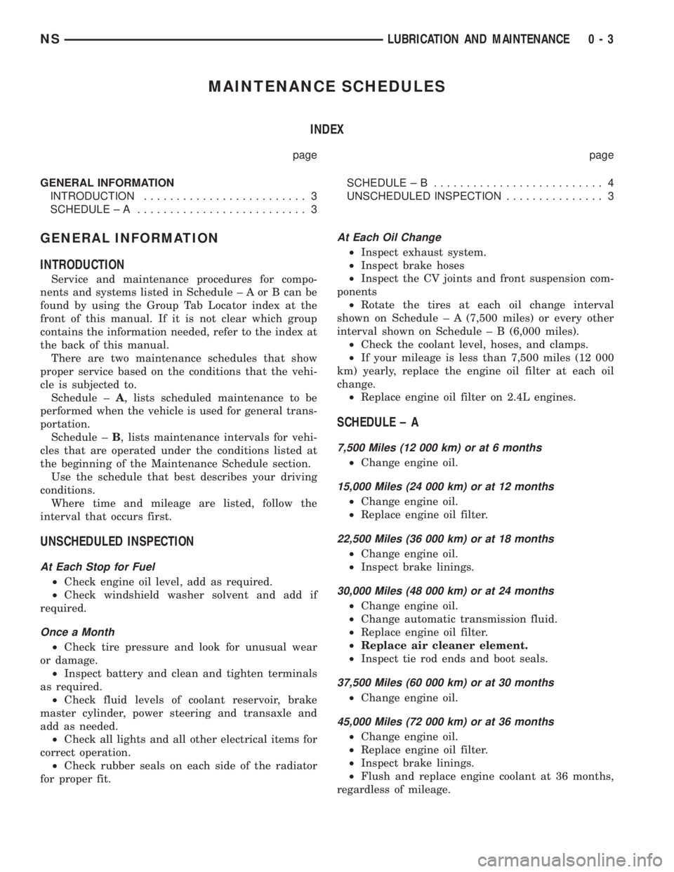
MAINTENANCE SCHEDULES
INDEX
page page
GENERAL INFORMATION
INTRODUCTION......................... 3
SCHEDULE ± A.......................... 3SCHEDULE ± B.......................... 4
UNSCHEDULED INSPECTION............... 3
GENERAL INFORMATION
INTRODUCTION
Service and maintenance procedures for compo-
nents and systems listed in Schedule ± A or B can be
found by using the Group Tab Locator index at the
front of this manual. If it is not clear which group
contains the information needed, refer to the index at
the back of this manual.
There are two maintenance schedules that show
proper service based on the conditions that the vehi-
cle is subjected to.
Schedule ±A, lists scheduled maintenance to be
performed when the vehicle is used for general trans-
portation.
Schedule ±B, lists maintenance intervals for vehi-
cles that are operated under the conditions listed at
the beginning of the Maintenance Schedule section.
Use the schedule that best describes your driving
conditions.
Where time and mileage are listed, follow the
interval that occurs first.
UNSCHEDULED INSPECTION
At Each Stop for Fuel
²Check engine oil level, add as required.
²Check windshield washer solvent and add if
required.
Once a Month
²Check tire pressure and look for unusual wear
or damage.
²Inspect battery and clean and tighten terminals
as required.
²Check fluid levels of coolant reservoir, brake
master cylinder, power steering and transaxle and
add as needed.
²Check all lights and all other electrical items for
correct operation.
²Check rubber seals on each side of the radiator
for proper fit.
At Each Oil Change
²Inspect exhaust system.
²Inspect brake hoses
²Inspect the CV joints and front suspension com-
ponents
²Rotate the tires at each oil change interval
shown on Schedule ± A (7,500 miles) or every other
interval shown on Schedule ± B (6,000 miles).
²Check the coolant level, hoses, and clamps.
²If your mileage is less than 7,500 miles (12 000
km) yearly, replace the engine oil filter at each oil
change.
²Replace engine oil filter on 2.4L engines.
SCHEDULE ± A
7,500 Miles (12 000 km) or at 6 months
²Change engine oil.
15,000 Miles (24 000 km) or at 12 months
²Change engine oil.
²Replace engine oil filter.
22,500 Miles (36 000 km) or at 18 months
²Change engine oil.
²Inspect brake linings.
30,000 Miles (48 000 km) or at 24 months
²Change engine oil.
²Change automatic transmission fluid.
²Replace engine oil filter.
²Replace air cleaner element.
²Inspect tie rod ends and boot seals.
37,500 Miles (60 000 km) or at 30 months
²Change engine oil.
45,000 Miles (72 000 km) or at 36 months
²Change engine oil.
²Replace engine oil filter.
²Inspect brake linings.
²Flush and replace engine coolant at 36 months,
regardless of mileage.
NSLUBRICATION AND MAINTENANCE 0 - 3
Page 28 of 1938
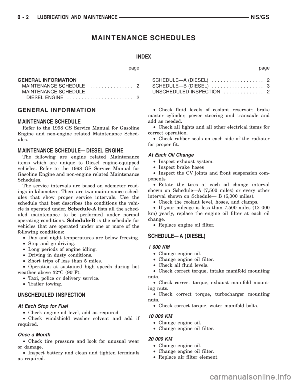
MAINTENANCE SCHEDULES
INDEX
page page
GENERAL INFORMATION
MAINTENANCE SCHEDULE............... 2
MAINTENANCE SCHEDULEÐ
DIESEL ENGINE....................... 2SCHEDULEÐA (DIESEL).................. 2
SCHEDULEÐB (DIESEL).................. 3
UNSCHEDULED INSPECTION.............. 2
GENERAL INFORMATION
MAINTENANCE SCHEDULE
Refer to the 1998 GS Service Manual for Gasoline
Engine and non-engine related Maintenance Sched-
ules.
MAINTENANCE SCHEDULEÐDIESEL ENGINE
The following are engine related Maintenance
items which are unique to Diesel engine-equipped
vehicles. Refer to the 1998 GS Service Manual for
Gasoline Engine and non-engine related Maintenance
Schedules.
The service intervals are based on odometer read-
ings in kilometers. There are two maintenance sched-
ules that show proper service intervals. Use the
schedule that best describes the conditions the vehi-
cle is operated under.Schedule-Alists all the sched-
uled maintenance to be performed under normal
operating conditions.Schedule-Bis the schedule for
vehicles that are operated under one or more of the
following conditions:
²Day and night temperatures are below freezing.
²Stop and go driving.
²Long periods of engine idling.
²Driving in dusty conditions.
²Short trips of less than 5 miles.
²Operation at sustained high speeds during hot
weather above 32ÉC (90ÉF).
²Taxi, police or delivery service.
²Trailer towing.
UNSCHEDULED INSPECTION
At Each Stop for Fuel
²Check engine oil level, add as required.
²Check windshield washer solvent and add if
required.
Once a Month
²Check tire pressure and look for unusual wear
or damage.
²Inspect battery and clean and tighten terminals
as required.²Check fluid levels of coolant reservoir, brake
master cylinder, power steering and transaxle and
add as needed.
²Check all lights and all other electrical items for
correct operation.
²Check rubber seals on each side of the radiator
for proper fit.
At Each Oil Change
²Inspect exhaust system.
²Inspect brake hoses
²Inspect the CV joints and front suspension com-
ponents
²Rotate the tires at each oil change interval
shown on ScheduleÐA (7,500 miles) or every other
interval shown on ScheduleÐ B (6,000 miles).
²Check the coolant level, hoses, and clamps.
²If your mileage is less than 7,500 miles (12 000
km) yearly, replace the engine oil filter at each oil
change.
²Replace engine oil filter.
SCHEDULEÐA (DIESEL)
1 000 KM
²Change engine oil.
²Change engine oil filter.
²Check all fluid levels.
²Check correct torque, intake manifold mounting
nuts.
²Check correct torque, exhaust manifold mount-
ing nuts.
²Check correct torque, turbocharger mounting
nuts.
²Check correct torque, water manifold bolts.
10 000 KM
²Change engine oil.
²Change engine oil filter.
20 000 KM
²Change engine oil.
²Change engine oil filter.
²Replace air filter element.
0 - 2 LUBRICATION AND MAINTENANCENS/GS
Page 36 of 1938
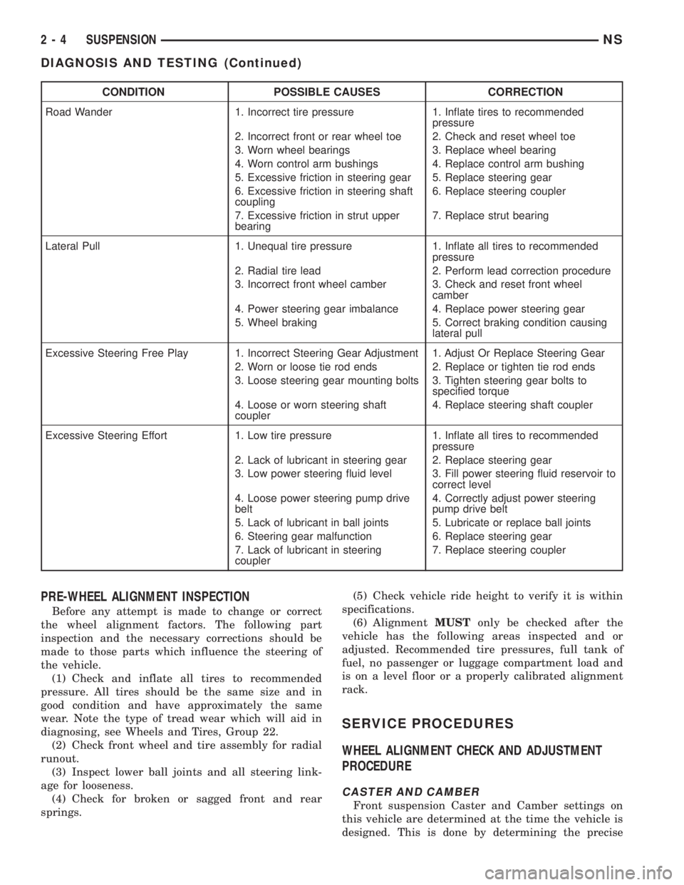
CONDITION POSSIBLE CAUSES CORRECTION
Road Wander 1. Incorrect tire pressure 1. Inflate tires to recommended
pressure
2. Incorrect front or rear wheel toe 2. Check and reset wheel toe
3. Worn wheel bearings 3. Replace wheel bearing
4. Worn control arm bushings 4. Replace control arm bushing
5. Excessive friction in steering gear 5. Replace steering gear
6. Excessive friction in steering shaft
coupling6. Replace steering coupler
7. Excessive friction in strut upper
bearing7. Replace strut bearing
Lateral Pull 1. Unequal tire pressure 1. Inflate all tires to recommended
pressure
2. Radial tire lead 2. Perform lead correction procedure
3. Incorrect front wheel camber 3. Check and reset front wheel
camber
4. Power steering gear imbalance 4. Replace power steering gear
5. Wheel braking 5. Correct braking condition causing
lateral pull
Excessive Steering Free Play 1. Incorrect Steering Gear Adjustment 1. Adjust Or Replace Steering Gear
2. Worn or loose tie rod ends 2. Replace or tighten tie rod ends
3. Loose steering gear mounting bolts 3. Tighten steering gear bolts to
specified torque
4. Loose or worn steering shaft
coupler4. Replace steering shaft coupler
Excessive Steering Effort 1. Low tire pressure 1. Inflate all tires to recommended
pressure
2. Lack of lubricant in steering gear 2. Replace steering gear
3. Low power steering fluid level 3. Fill power steering fluid reservoir to
correct level
4. Loose power steering pump drive
belt4. Correctly adjust power steering
pump drive belt
5. Lack of lubricant in ball joints 5. Lubricate or replace ball joints
6. Steering gear malfunction 6. Replace steering gear
7. Lack of lubricant in steering
coupler7. Replace steering coupler
PRE-WHEEL ALIGNMENT INSPECTION
Before any attempt is made to change or correct
the wheel alignment factors. The following part
inspection and the necessary corrections should be
made to those parts which influence the steering of
the vehicle.
(1) Check and inflate all tires to recommended
pressure. All tires should be the same size and in
good condition and have approximately the same
wear. Note the type of tread wear which will aid in
diagnosing, see Wheels and Tires, Group 22.
(2) Check front wheel and tire assembly for radial
runout.
(3) Inspect lower ball joints and all steering link-
age for looseness.
(4) Check for broken or sagged front and rear
springs.(5) Check vehicle ride height to verify it is within
specifications.
(6) AlignmentMUSTonly be checked after the
vehicle has the following areas inspected and or
adjusted. Recommended tire pressures, full tank of
fuel, no passenger or luggage compartment load and
is on a level floor or a properly calibrated alignment
rack.
SERVICE PROCEDURES
WHEEL ALIGNMENT CHECK AND ADJUSTMENT
PROCEDURE
CASTER AND CAMBER
Front suspension Caster and Camber settings on
this vehicle are determined at the time the vehicle is
designed. This is done by determining the precise
2 - 4 SUSPENSIONNS
DIAGNOSIS AND TESTING (Continued)
Page 40 of 1938
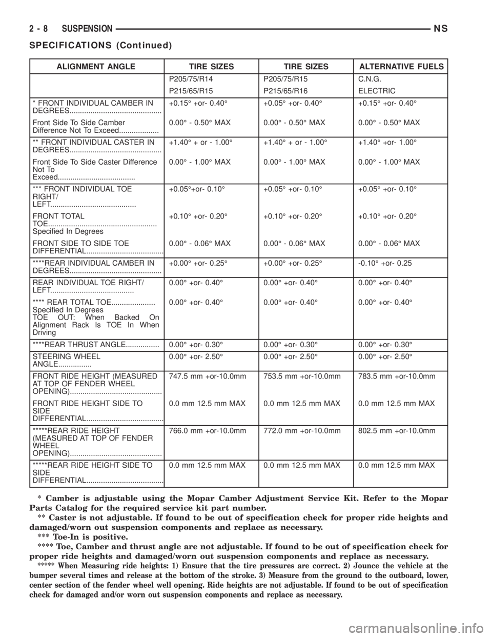
* Camber is adjustable using the Mopar Camber Adjustment Service Kit. Refer to the Mopar
Parts Catalog for the required service kit part number.
** Caster is not adjustable. If found to be out of specification check for proper ride heights and
damaged/worn out suspension components and replace as necessary.
*** Toe-In is positive.
**** Toe, Camber and thrust angle are not adjustable. If found to be out of specification check for
proper ride heights and damaged/worn out suspension components and replace as necessary.
***** When Measuring ride heights: 1) Ensure that the tire pressures are correct. 2) Jounce the vehicle at the
bumper several times and release at the bottom of the stroke. 3) Measure from the ground to the outboard, lower,
center section of the fender wheel well opening. Ride heights are not adjustable. If found to be out of specification
check for damaged and/or worn out suspension components and replace as necessary.
ALIGNMENT ANGLE TIRE SIZES TIRE SIZES ALTERNATIVE FUELS
P205/75/R14 P205/75/R15 C.N.G.
P215/65/R15 P215/65/R16 ELECTRIC
* FRONT INDIVIDUAL CAMBER IN
DEGREES............................................+0.15É +or- 0.40É +0.05É +or- 0.40É +0.15É +or- 0.40É
Front Side To Side Camber
Difference Not To Exceed...................0.00É - 0.50É MAX 0.00É - 0.50É MAX 0.00É - 0.50É MAX
** FRONT INDIVIDUAL CASTER IN
DEGREES............................................+1.40É + or - 1.00É +1.40É + or - 1.00É +1.40É +or- 1.00É
Front Side To Side Caster Difference
Not To
Exceed.....................................0.00É - 1.00É MAX 0.00É - 1.00É MAX 0.00É - 1.00É MAX
*** FRONT INDIVIDUAL TOE
RIGHT/
LEFT.........................................+0.05É+or- 0.10É +0.05É +or- 0.10É +0.05É +or- 0.10É
FRONT TOTAL
TOE....................................................
Specified In Degrees+0.10É +or- 0.20É +0.10É +or- 0.20É +0.10É +or- 0.20É
FRONT SIDE TO SIDE TOE
DIFFERENTIAL.....................................0.00É - 0.06É MAX 0.00É - 0.06É MAX 0.00É - 0.06É MAX
****REAR INDIVIDUAL CAMBER IN
DEGREES............................................+0.00É +or- 0.25É +0.00É +or- 0.25É -0.10É +or- 0.25
REAR INDIVIDUAL TOE RIGHT/
LEFT........................................0.00É +or- 0.40É 0.00É +or- 0.40É 0.00É +or- 0.40É
**** REAR TOTAL TOE.....................
Specified In Degrees
TOE OUT: When Backed On
Alignment Rack Is TOE In When
Driving0.00É +or- 0.40É 0.00É +or- 0.40É 0.00É +or- 0.40É
****REAR THRUST ANGLE................ 0.00É +or- 0.30É 0.00É +or- 0.30É 0.00É +or- 0.30É
STEERING WHEEL
ANGLE................0.00É +or- 2.50É 0.00É +or- 2.50É 0.00É +or- 2.50É
FRONT RIDE HEIGHT (MEASURED
AT TOP OF FENDER WHEEL
OPENING)............................................747.5 mm +or-10.0mm 753.5 mm +or-10.0mm 783.5 mm +or-10.0mm
FRONT RIDE HEIGHT SIDE TO
SIDE
DIFFERENTIAL.....................................0.0 mm 12.5 mm MAX 0.0 mm 12.5 mm MAX 0.0 mm 12.5 mm MAX
*****REAR RIDE HEIGHT
(MEASURED AT TOP OF FENDER
WHEEL
OPENING)............................................766.0 mm +or-10.0mm 772.0 mm +or-10.0mm 802.5 mm +or-10.0mm
*****REAR RIDE HEIGHT SIDE TO
SIDE
DIFFERENTIAL.....................................0.0 mm 12.5 mm MAX 0.0 mm 12.5 mm MAX 0.0 mm 12.5 mm MAX
2 - 8 SUSPENSIONNS
SPECIFICATIONS (Continued)
Page 171 of 1938
fluid accumulators temporarily store brake fluid that
is decayed from the wheel brakes during an ABS
cycle. This stored brake fluid is then used by the
pump in the HCU to provide build pressure for the
brake hydraulic system.
Additionally on vehicles that are equipped with
only ABS (non-traction control vehicles) there is a
mini brake fluid accumulator on the secondary
hydraulic circuit which protects the master cylinder's
seals during an ABS stop. There is also a noise
damping chamber on the primary hydraulic circuit.
On ABS equipped vehicles with traction control, in
addition to the brake fluid accumulators there are
also two noise damping chambers in the HCU.
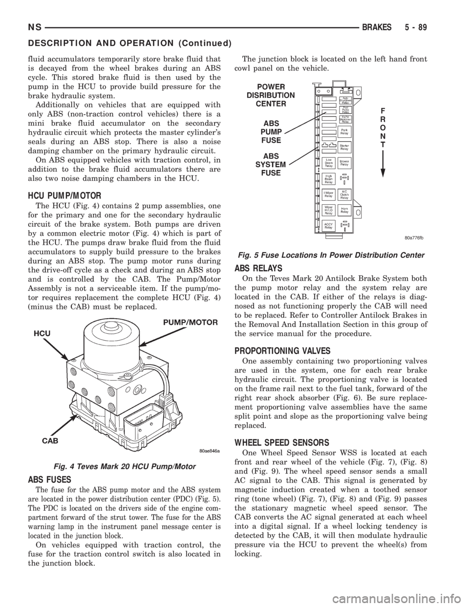
HCU PUMP/MOTOR
The HCU (Fig. 4) contains 2 pump assemblies, one
for the primary and one for the secondary hydraulic
circuit of the brake system. Both pumps are driven
by a common electric motor (Fig. 4) which is part of
the HCU. The pumps draw brake fluid from the fluid
accumulators to supply build pressure to the brakes
during an ABS stop. The pump motor runs during
the drive-off cycle as a check and during an ABS stop
and is controlled by the CAB. The Pump/Motor
Assembly is not a serviceable item. If the pump/mo-
tor requires replacement the complete HCU (Fig. 4)
(minus the CAB) must be replaced.
ABS FUSES
The fuse for the ABS pump motor and the ABS system
are located in the power distribution center (PDC) (Fig. 5).
The PDC is located on the drivers side of the engine com-
partment forward of the strut tower. The fuse for the ABS
warning lamp in the instrument panel message center is
located in the junction block.
On vehicles equipped with traction control, the
fuse for the traction control switch is also located in
the junction block.The junction block is located on the left hand front
cowl panel on the vehicle.
ABS RELAYS
On the Teves Mark 20 Antilock Brake System both
the pump motor relay and the system relay are
located in the CAB. If either of the relays is diag-
nosed as not functioning properly the CAB will need
to be replaced. Refer to Controller Antilock Brakes in
the Removal And Installation Section in this group of
the service manual for the procedure.
PROPORTIONING VALVES
One assembly containing two proportioning valves
are used in the system, one for each rear brake
hydraulic circuit. The proportioning valve is located
on the frame rail next to the fuel tank, forward of the
right rear shock absorber (Fig. 6). Be sure replace-
ment proportioning valve assemblies have the same
split point and slope as the proportioning valve being
replaced.
WHEEL SPEED SENSORS
One Wheel Speed Sensor WSS is located at each
front and rear wheel of the vehicle (Fig. 7), (Fig. 8)
and (Fig. 9). The wheel speed sensor sends a small
AC signal to the CAB. This signal is generated by
magnetic induction created when a toothed sensor
ring (tone wheel) (Fig. 7), (Fig. 8) and (Fig. 9) passes
the stationary magnetic wheel speed sensor. The
CAB converts the AC signal generated at each wheel
into a digital signal. If a wheel locking tendency is
detected by the CAB, it will then modulate hydraulic
pressure via the HCU to prevent the wheel(s) from
locking.
Fig. 4 Teves Mark 20 HCU Pump/Motor
Fig. 5 Fuse Locations In Power Distribution Center
NSBRAKES 5 - 89
DESCRIPTION AND OPERATION (Continued)
Page 300 of 1938
²available manifold vacuum
²barometric pressure
²engine coolant temperature
²engine RPM
²intake air temperature (2.4L only)
²throttle position
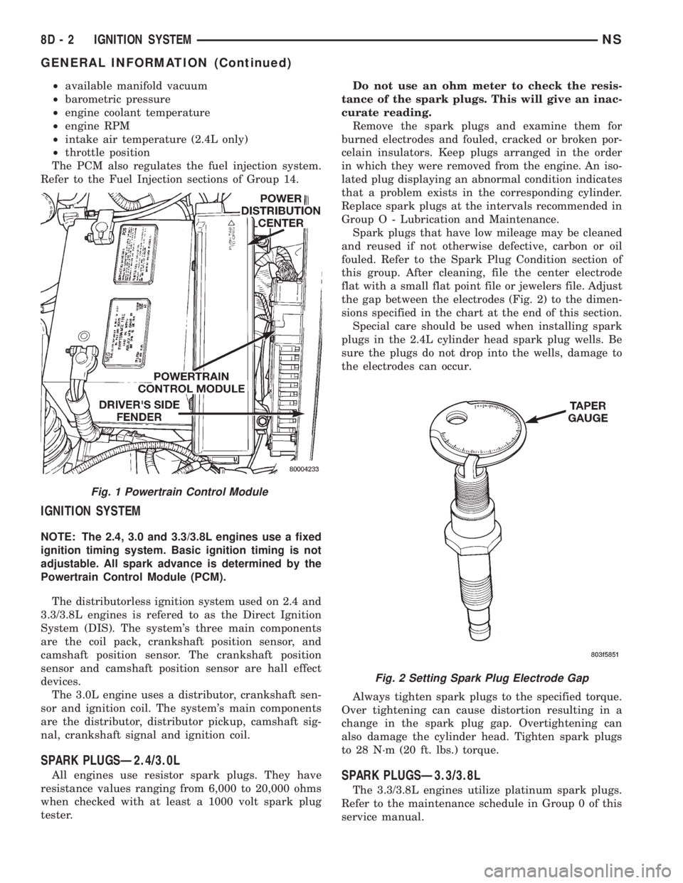
The PCM also regulates the fuel injection system.
Refer to the Fuel Injection sections of Group 14.
IGNITION SYSTEM
NOTE: The 2.4, 3.0 and 3.3/3.8L engines use a fixed
ignition timing system. Basic ignition timing is not
adjustable. All spark advance is determined by the
Powertrain Control Module (PCM).
The distributorless ignition system used on 2.4 and
3.3/3.8L engines is refered to as the Direct Ignition
System (DIS). The system's three main components
are the coil pack, crankshaft position sensor, and
camshaft position sensor. The crankshaft position
sensor and camshaft position sensor are hall effect
devices.
The 3.0L engine uses a distributor, crankshaft sen-
sor and ignition coil. The system's main components
are the distributor, distributor pickup, camshaft sig-
nal, crankshaft signal and ignition coil.
SPARK PLUGSÐ2.4/3.0L
All engines use resistor spark plugs. They have
resistance values ranging from 6,000 to 20,000 ohms
when checked with at least a 1000 volt spark plug
tester.Do not use an ohm meter to check the resis-
tance of the spark plugs. This will give an inac-
curate reading.
Remove the spark plugs and examine them for
burned electrodes and fouled, cracked or broken por-
celain insulators. Keep plugs arranged in the order
in which they were removed from the engine. An iso-
lated plug displaying an abnormal condition indicates
that a problem exists in the corresponding cylinder.
Replace spark plugs at the intervals recommended in
Group O - Lubrication and Maintenance.
Spark plugs that have low mileage may be cleaned
and reused if not otherwise defective, carbon or oil
fouled. Refer to the Spark Plug Condition section of
this group. After cleaning, file the center electrode
flat with a small flat point file or jewelers file. Adjust
the gap between the electrodes (Fig. 2) to the dimen-
sions specified in the chart at the end of this section.
Special care should be used when installing spark
plugs in the 2.4L cylinder head spark plug wells. Be
sure the plugs do not drop into the wells, damage to
the electrodes can occur.
Always tighten spark plugs to the specified torque.
Over tightening can cause distortion resulting in a
change in the spark plug gap. Overtightening can
also damage the cylinder head. Tighten spark plugs
to 28 N´m (20 ft. lbs.) torque.SPARK PLUGSÐ3.3/3.8L
The 3.3/3.8L engines utilize platinum spark plugs.
Refer to the maintenance schedule in Group 0 of this
service manual.
Fig. 1 Powertrain Control Module
Fig. 2 Setting Spark Plug Electrode Gap
8D - 2 IGNITION SYSTEMNS
GENERAL INFORMATION (Continued)
Page 304 of 1938

cylinder 4 crankshaft timing marks follow. One cam-
shaft pulse after the 3 pulses indicates cylinder 5.
The 2 camshaft pulses after cylinder 5 signals cylin-
der 6 (Fig. 10). The PCM can synchronize on cylin-
ders1or4.
When metal aligns with the sensor, voltage goes
low (less than 0.3 volts). When a notch aligns with
the sensor, voltage switches high (5.0 volts). As a
group of notches pass under the sensor, the voltage
switches from low (metal) to high (notch) then back
to low. The number of notches determine the amount
of pulses. If available, an oscilloscope can display the
square wave patterns of each timing event.
Top Dead Center (TDC) does not occur when
notches on the camshaft sprocket pass below the cyl-
inder. TDC occurs after the camshaft pulse (or
pulses) and after the 4 crankshaft pulses associated
with the particular cylinder. The arrows and cylinder
call outs on Figure 4 represent which cylinder the
flat spot and notches identify, they do not indicate
TDC position.
The camshaft position sensor is mounted in the
front of the timing case cover (Fig. 11).
MANIFOLD ABSOLUTE PRESSURE (MAP) SENSOR
The MAP sensor reacts to absolute pressure in the
intake manifold and provides an input voltage to the
Powertrain Control Module (PCM). As engine load
changes, manifold pressure varies. The changes in
engine load cause the MAP sensors resistance to
change. The change in MAP sensor resistance results
in a different input voltage to the PCM.
The input voltage level supplies the PCM with
information relating to ambient barometric pressure
during engine start-up (cranking) and engine load
while its operating. Based on MAP sensor voltage
and inputs from other sensors, the PCM adjusts
spark advance and the air-fuel mixture.
ENGINE COOLANT TEMPERATURE (ECT) SENSOR
The ECT sensor is located next to the thermostat
housing (Fig. 12). The sensor provides an input volt-
age to the Powertrain Control Module (PCM). Thesensor is a variable resistance (thermistor) with a
range of -40ÉF to 265ÉF. As coolant temperature var-
ies, the sensors resistance changes, resulting in a dif-
ferent input voltage to the PCM.
The PCM contains different spark advance sched-
ules for cold and warm engine operation. The sched-
ules reduce engine emission and improve driveability.
When the engine is cold, the PCM will demand
slightly richer air-fuel mixtures and higher idle
speeds until normal operating temperatures are
reached.
The ECT sensor input is also used for cooling fan
control.
Fig. 9 Camshaft Position Sensor
Fig. 10 Camshaft Sprocket
Fig. 11 Camshaft Position Sensor Location
8D - 6 IGNITION SYSTEMNS
GENERAL INFORMATION (Continued)
Page 309 of 1938
either the crankshaft position sensor/camshaft posi-
tion sensor 8 volt supply circuit, or the camshaft
position sensor output or ground circuits. Use the
DRB scan tool to test the camshaft position sensor
and the sensor circuits. Refer to the appropriate Pow-
ertrain Diagnostics Procedure Manual. Refer to the
wiring diagrams section for circuit information.
IGNITION TIMING PROCEDURE
The engines for this vehicle, use a fixed ignition
system. The PCM regulates ignition timing. Basic
ignition timing is not adjustable.
MANIFOLD ABSOLUTE PRESSURE (MAP) SENSOR
TEST
Refer to Group 14, Fuel System for Diagnosis and
Testing.
CAMSHAFT POSITION SENSOR AND CRANKSHAFT
POSITION SENSOR
The output voltage of a properly operating cam-
shaft position sensor or crankshaft position sensor
switches from high (5.0 volts) to low (0.3 volts). By
connecting an Moper Diagonostic System (MDS) and
engine analyzer to the vehicle, technicians can view
the square wave pattern.
ENGINE COOLANT TEMPERATURE SENSOR
Refer to Group 14, Fuel System for Diagnosis and
Testing.
INTAKE AIR TEMPERATURE SENSOR
Refer to Group 14, Fuel System, for Diagnosis and
Testing.
SPARK PLUG CONDITION
NORMAL OPERATING CONDITIONS
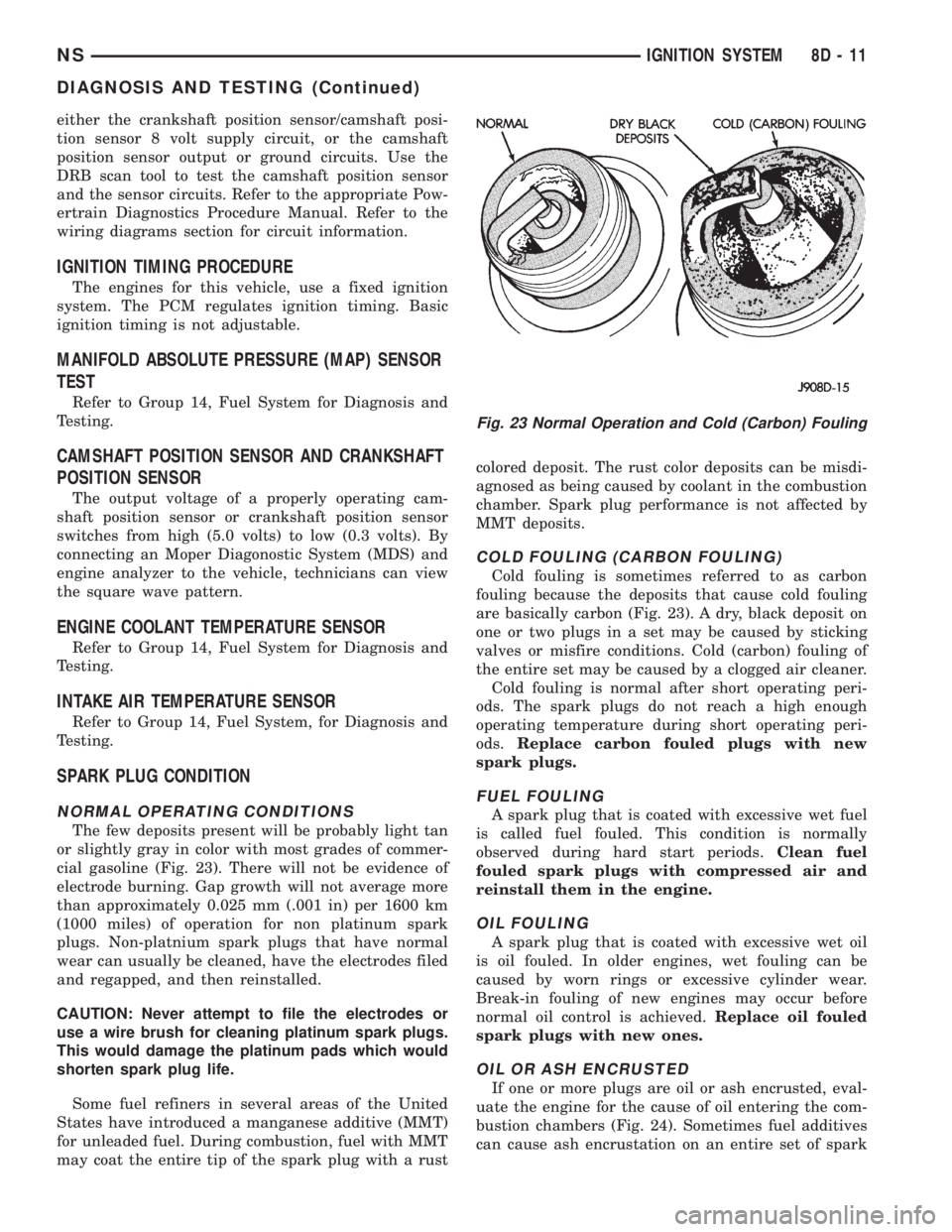
The few deposits present will be probably light tan
or slightly gray in color with most grades of commer-
cial gasoline (Fig. 23). There will not be evidence of
electrode burning. Gap growth will not average more
than approximately 0.025 mm (.001 in) per 1600 km
(1000 miles) of operation for non platinum spark
plugs. Non-platnium spark plugs that have normal
wear can usually be cleaned, have the electrodes filed
and regapped, and then reinstalled.
CAUTION: Never attempt to file the electrodes or
use a wire brush for cleaning platinum spark plugs.
This would damage the platinum pads which would
shorten spark plug life.
Some fuel refiners in several areas of the United
States have introduced a manganese additive (MMT)
for unleaded fuel. During combustion, fuel with MMT
may coat the entire tip of the spark plug with a rustcolored deposit. The rust color deposits can be misdi-
agnosed as being caused by coolant in the combustion
chamber. Spark plug performance is not affected by
MMT deposits.
COLD FOULING (CARBON FOULING)
Cold fouling is sometimes referred to as carbon
fouling because the deposits that cause cold fouling
are basically carbon (Fig. 23). A dry, black deposit on
one or two plugs in a set may be caused by sticking
valves or misfire conditions. Cold (carbon) fouling of
the entire set may be caused by a clogged air cleaner.
Cold fouling is normal after short operating peri-
ods. The spark plugs do not reach a high enough
operating temperature during short operating peri-
ods.Replace carbon fouled plugs with new
spark plugs.
FUEL FOULING
A spark plug that is coated with excessive wet fuel
is called fuel fouled. This condition is normally
observed during hard start periods.Clean fuel
fouled spark plugs with compressed air and
reinstall them in the engine.
OIL FOULING
A spark plug that is coated with excessive wet oil
is oil fouled. In older engines, wet fouling can be
caused by worn rings or excessive cylinder wear.
Break-in fouling of new engines may occur before
normal oil control is achieved.Replace oil fouled
spark plugs with new ones.
OIL OR ASH ENCRUSTED
If one or more plugs are oil or ash encrusted, eval-
uate the engine for the cause of oil entering the com-
bustion chambers (Fig. 24). Sometimes fuel additives
can cause ash encrustation on an entire set of spark
Fig. 23 Normal Operation and Cold (Carbon) Fouling
NSIGNITION SYSTEM 8D - 11
DIAGNOSIS AND TESTING (Continued)
Page 318 of 1938

(1) Install target magnet in end of camshaft.
Tighten mounting screw to 5.65 N´m (50 in. lbs.)
torque.
(2) Install a new O-ring on sensor.
(3) Install camshaft position sensor. Tighten sensor
mounting screws to 9.6 N´m (85 in. lbs.) torque.
(4) Attach engine harness connector to camshaft
position sensor.
(5) Install air cleaner inlet tube and filtered air
tube.
MANIFOLD ABSOLUTE PRESSURE (MAP)
SENSORÐ2.4/3.3/3.8L
REMOVAL
(1) Disconnect electrical connector from MAP sen-
sor (Fig. 12).
(2) Remove two screws holding sensor to the
intake manifold.
INSTALLATION
(1) Reverse the above procedure for installation.
THROTTLE POSITION SENSOR
Refer to Group 14, Fuel Injection Section, for
Removal/Installation.
ENGINE COOLANT TEMPERATURE SENSORÐ2.4L
The coolant sensor threads into the top of the ther-
mostat housing (Fig. 13). New sensors have sealant
applied to the threads.
WARNING: HOT, PRESSURIZED COOLANT CAN
CAUSE INJURY BY SCALDING. COOLING SYSTEM
MUST BE PARTIALLY DRAINED BEFORE REMOV-
ING THE COOLANT TEMPERATURE SENSOR.
REFER TO GROUP 7- COOLING.
Fig. 10 Target Magnet
Fig. 11 Target Magnet Installation
Fig. 12 Map Absolute Pressure Sensor
Fig. 13 Engine Coolant Temperature SensorÐ2.4L
8D - 20 IGNITION SYSTEMNS
REMOVAL AND INSTALLATION (Continued)
Page 321 of 1938

3.0L ENGINE
INDEX
page page
DESCRIPTION AND OPERATION
CAMSHAFT POSITION SENSOR............ 23
FIRING ORDERÐ3.0L.................... 23
MANIFOLD ABSOLUTE PRESSURE (MAP)
SENSOR............................. 23
REMOVAL AND INSTALLATION
CRANKSHAFT POSITION SENSOR.......... 25
ENGINE COOLANT TEMPERATURE SENSORÐ
3.0L................................. 25
IGNITION COILÐ3.OL.................... 24
MANIFOLD ABSOLUTE PRESSURE (MAP)
SENSORÐ3.0L........................ 24SPARK PLUG SERVICE................... 24
THROTTLE POSITION SENSOR............ 25
DISASSEMBLY AND ASSEMBLY
DISTRIBUTORÐ3.0L..................... 26
CLEANING AND INSPECTION
DISTRIBUTOR CAP...................... 26
DISTRIBUTOR ROTORÐ3.0L............... 27
SPECIFICATIONS
SPARK PLUG CABLE RESISTANCEÐ3.0L..... 27
SPARK PLUG........................... 27
TORQUE.............................. 27
DESCRIPTION AND OPERATION
FIRING ORDERÐ3.0L
MANIFOLD ABSOLUTE PRESSURE (MAP) SENSOR
The MAP sensor reacts to absolute pressure in the
intake manifold and provides an input voltage to the
Powertrain Control Module (PCM). As engine load
changes, manifold pressure varies. The changes in
engine load cause the MAP sensors resistance to
change. The change in MAP sensor resistance results
in a different input voltage to the PCM.
The input voltage level supplies the PCM with
information relating to ambient barometric pressure
during engine start-up (cranking) and engine load
while its operating. Based on MAP sensor voltage
and inputs from other sensors, the PCM adjusts
spark advance and the air-fuel mixture.
CAMSHAFT POSITION SENSOR
The PCM determines fuel injection synchronization
and cylinder identification from inputs provided by
the camshaft position sensor and crankshaft position
sensor. From the two inputs, the PCM determines
crankshaft position.
The 3.0L engine is equipped with a camshaft
driven mechanical distributor, containing a shaft
driven distributor rotor. The distributor is also
equipped with an internal camshaft position (fuel
sync) sensor (Fig. 1). This sensor provides fuel injec-
tion synchronization and cylinder identification to
the PCM.
The camshaft position sensor contains a hall effect
device callled a sync signal generator. This sync sig-
nal generator detects a rotating pulse ring (shutter)
on the distributor shaft. The pulse ring rotates 180
through the sync signal generator. Its signal is used
in conjunction with the crankshaft position sensor to
differentiate between fuel injection and spark events.
It is also used to synchronize the fuel injectors with
their respective cylinders.
When the leading edge of the shutter enters the
sync signal generator, the interruption of magnetic
field causes the voltage to switch high. This causes a
sync signal of approximately 5 volts.
When the trailing edge of the shutter leaves the
sync signal generator, the change of magnetic field
causes the sync signal voltage to switch low to 0
volts.
Since the shutter rotates at half crankshaft speed,
it may take 1 engine revolution during cranking for
the PCM to determine the position of piston number
6.
SPARK PLUG WIRE ROUTINGÐ3.0L ENGINE
NSIGNITION SYSTEM 8D - 23