seat memory CHRYSLER VOYAGER 1996 Service Manual
[x] Cancel search | Manufacturer: CHRYSLER, Model Year: 1996, Model line: VOYAGER, Model: CHRYSLER VOYAGER 1996Pages: 1938, PDF Size: 55.84 MB
Page 179 of 1938
START-UP CYCLE
The self diagnostic ABS start up cycle begins when
the ignition switch is turned to the on position. Elec-
trical checks are completed on ABS components, such
as the Controller, solenoid continuity, and the system
relay operation. During this check the Amber ABS
Warning Light is turned on for approximately 4 sec-
onds and the brake pedal may emit a popping sound
and move slightly when the solenoid valves are
checked.
DRIVE-OFF CYCLE
Further Functional testing is accomplished once
the vehicle is set in motion and reaches a speed of
about 20 kph (12 mph.). This cycle is performed only
once after each ignition on/off cycle.
²The pump/motor is activated briefly to verify
function. When the pump/motor is activated a whirl-
ing or buzzing sound may be heard by the driver,
which is normal when the pump/motor is running.
²The wheel speed sensor output is verified to be
within the correct operating range.
ONGOING TESTS
Other tests are performed on a continuous basis.
These include checks for solenoid continuity, wheel
speed sensor continuity and wheel speed sensor out-
put.
ABS DIAGNOSTIC TROUBLE CODES
Diagnostic trouble codes (DTC) are kept in the con-
troller's memory until either erased by the technician
using the DRB or erased automatically after 3500
miles. DTC's are retained by the controller even if
the ignition is turned off or the battery is discon-
nected. More than one DTC can be stored at a time.
The mileage of the most recent occurrence, number of
occurrences and the DTC that was stored is also dis-
played. Most functions of the CAB and the ABS sys-
tem can be accessed by the technician for testing and
diagnostic purposes by using the DRB.
LATCHING VERSUS NON-LATCHING
DIAGNOSTIC TROUBLE CODES
Some DTC's detected by the CAB are latching; the
DTC is latched and ABS braking is disabled until the
ignition switch is reset. Thus ABS braking is non
operational even if the original DTC has disappeared.
Other DTC's are non-latching; any warning lights
that are turned on, are only turned on as long as the
DTC condition exists. As soon as the condition goes
away, the ABS Warning Light is turned off, although
a DTC will be set in most cases.
INTERMITTENT DIAGNOSTIC TROUBLE CODES
As with virtually any electronic system, intermit-
tent electrical problems in the ABS system may be
difficult to accurately diagnose.
Most intermittent electrical problems are caused
by faulty electrical connections or wiring. When an
intermittent fault is encountered, check suspect cir-
cuits for:
A visual inspection for loose, disconnected, or mis-
routed wires should be done before attempting to
diagnose or service the ITT Teves Mark 20 antilock
brake system. A visual inspection will eliminate
unnecessary testing and diagnostics time. A thorough
visual inspection will include the following compo-
nents and areas of the vehicle.
(1) Inspect fuses in the power distribution center
(PDC) and the wiring junction block. Verify that all
fuses are fully inserted into the PDC and wring junc-
tion block. A label on the underside of the PDC cover
identifies the locations of the ABS fuses in the PDC.
(2) Inspect the 25-way electrical connector at the
CAB for damage, spread or backed-out wiring termi-
nals. Verify that the 25-way connector is fully
inserted in the socket on the CAB. Be sure that wires
are not stretched tight or pulled out of the connector.
(3) Verify that all the wheel speed sensor connec-
tions are secure.
(4) Poor mating of connector halves or terminals
not fully seated in the connector body.
(5) Improperly formed or damaged terminals. All
connector terminals in a suspect circuit should be
carefully reformed to increase contact tension.
(6) Poor terminal to wire connection. This requires
removing the terminal from the connector body to
inspect.
(7) Pin presence in the connector assembly
(8) Proper ground connections. Check all ground
connections for signs of corrosion, tight fasteners, or
other potential defects. Refer to wiring diagram man-
ual for ground locations.
(9) Problems with main power sources of the vehi-
cle. Inspect battery, generator, ignition circuits and
other related relays and fuses.
(10) If a visual check does not find the cause of the
problem, operate the car in an attempt to duplicate
the condition and record the trouble code.
(11) Most failures of the ABS system will disable
ABS function for the entire ignition cycle even if the
fault clears before key-off. There are some failure
conditions, however, which will allow ABS operation
to resume during the ignition cycle in which a failure
occurred if the failure conditions are no longer
present. The following conditions may result in inter-
mittent illumination of the ABS Warning Lamp. All
other failures will cause the lamp to remain on until
the ignition switch is turned off. Circuits involving
NSBRAKES 5 - 97
DIAGNOSIS AND TESTING (Continued)
Page 513 of 1938
REMOTE KEYLESS ENTRY
INDEX
page page
DESCRIPTION AND OPERATION
INTRODUCTION......................... 5
VEHICLE ACCESS CODE (VAC)
PROGRAMMING........................ 5
DIAGNOSIS AND TESTING
RKE DIAGNOSTICS....................... 5
SERVICE PROCEDURES
HORN CHIRP DISABLE OR ENABLE.......... 6REMOVAL AND INSTALLATION
RKE MODULE........................... 6
ADJUSTMENTS
PROGRAMMING RKE MODULE.............. 6
SPECIFICATIONS
RKE TRANSMITTER BATTERY.............. 6
RKE TRANSMITTER RANGE................ 6
DESCRIPTION AND OPERATION
INTRODUCTION
The key fob transmitter has three buttons to actu-
ate and program the Remote Keyless Entry (RKE)
system (Fig. 1).
²UNLOCK: Pressing the UNLOCK button once
will unlock the driver door and activate the illumi-
nated entry system and disarm Vehicle Theft Secu-
rity System, if equipped. Pressing the UNLOCK
button twice within five seconds will unlock all doors
and activate the illuminated entry system.
²LOCK: Pressing the LOCK button locks all
doors and sounds horn (chirp) and arm the Vehicle
Theft Security System. The chirp verifies the door
lock operation.
²PANIC: Pressing the PANIC button sounds the
horns at half second intervals, flashes the exterior
lamps, and turns ON the interior lamps. The panic
alarm will remain on for three minutes, or until the
PANIC button is actuated again or the ignition
switch is turned to the RUN position.
²The Remote Keyless Entry Module is capable of
retaining the transmitter Vehicle Access Code(s)
(VAC) in its memory even after vehicle power has
been interrupted.
²The RKE system activates the optional memory
seat and mirror system, if equipped. Two primary
key fob transmitters can be programmed to actuate
memory seat and mirror setting 1 or 2. Two addi-
tional key fob transmitters can be added, but they
will not be able to operate the memory seat and mir-
ror system. Refer to Group 8R, Power Seats and
Group 8T, Power Mirrors for memory system infor-
mation.
VEHICLE ACCESS CODE (VAC) PROGRAMMING
The RKE module is capable of retaining up to four
different Vehicle Access Codes. Whenever the vehicle
battery power is interrupted the RKE Module willretain all vehicle access codes in its memory. When
replacing or adding a key fob transmitter (maximum
4) a functional key fob transmitter is required to pro-
gram the RKE Module to accept the new Vehicle
Access Code. If a functional key fob transmitter is
not available, a scan tool (DRB) can be used to pro-
gram the RKE Module. Refer to the proper Body
Diagnostic Procedures manual for Vehicle Access
Code programming procedures using a scan tool.
DIAGNOSIS AND TESTING
RKE DIAGNOSTICS
Refer to Group 8W, Wiring Diagrams for circuit
information and component locations. Refer to the
proper Body Diagnostic Procedures manual for test-
ing the Remote Keyless Entry system using a scan
tool (DRB). Also refer to other interrelated systems
groups within this manual:
²Group 8Q, Vehicle Theft Security System
²Group 8R, Power Seats
²Group 8T, Power Mirrors
Fig. 1 Key Fob Transmitter
NSPOWER DOOR LOCKS 8P - 5
Page 514 of 1938
SERVICE PROCEDURES
HORN CHIRP DISABLE OR ENABLE
The horn chirp can be DISABLED or ENABLED
using the following procedure.
To DISABLE (cancelling) the horn chirp feature,
press and hold the transmitter LOCK button for a
minimum four seconds. While pressing LOCK button
in, press the UNLOCK button. The horn chirp fea-
ture will not function until the above procedure is
repeated. To ENABLE (reinstate) the horn chirp fea-
ture, use any one of the four key fob transmitters
and reverse the above procedures. It will ENABLE
the horn chirp feature for all transmitters.
REMOVAL AND INSTALLATION
RKE MODULE
REMOVAL
(1) Remove instrument panel top cover. Refer to
Group 8E, Instrument Panel and Gauges for proper
procedures.
(2) Remove screws holding RKE module to instru-
ment panel.
(3) Disconnect wire connector from RKE module
(Fig. 2).
(4) Remove the RKE module.
INSTALLATION
For installation, reverse the above procedures.
ADJUSTMENTS
PROGRAMMING RKE MODULE
(1) Using a functional key fob transmitter, unlock
the vehicle and disarm the Vehicle Theft Security
System.
(2) Insert ignition key into the ignition switch.
(3) Turn the ignition switch to RUN position with-
out starting engine.
(4) Using a functional key fob transmitter, press
and hold the UNLOCK button for a minimum four
seconds (maximum ten seconds).
(5) While holding UNLOCK button, and before ten
seconds passes, press and release the PANIC button.
A single chime will sound to verify that the RKE
module is set to receive the new Vehicle Access
Code(s).
(6) Within 30 seconds of the chime, press any but-
ton on each new key fob transmitter. After 30 sec-
onds or when ignition switch is turned OFF, the RKE
module will end the programming mode. A single
chime will sound to verify that the RKE module will
no longer receive additional Vehicle Access Code(s).
(7) When Vehicle Access Code(s) programming is
complete, turn Ignition Switch to the OFF position
and verify RKE system operation using each key fob.
NOTE: Only the primary (first two) key fob transmit-
ters will operate the memory seat and mirror sys-
tems. If a primary key fob is being replaced, the
memory seat and mirror module will require pro-
gramming. Refer to Group 8R, Power Seats for
proper (data link) programming procedure.
SPECIFICATIONS
RKE TRANSMITTER BATTERY
The batteries can be removed without special tools
and are readily available at local retail stores. The
recommended battery is Duracell DL 2016 or equiva-
lent. Battery life is about one to two years.
CAUTION: Do not touch the battery terminals or
handle the batteries any more than necessary.
Hands must be clean and dry.
RKE TRANSMITTER RANGE
Normal operation range is up to about a distance
of 7 meters (23 ft.) of the vehicle. Range may be bet-
ter or worse depending on the environment around
the vehicle. Closeness to a radio frequency transmit-
ter such as a radio station tower may degrade oper-
ational range, while range in an open field will be
enhanced.
Fig. 2 RKE Module
8P - 6 POWER DOOR LOCKSNS
Page 529 of 1938
POWER SEATS
CONTENTS
page page
MEMORY SEAT AND MIRROR SYSTEM....... 3POWER SEATS........................... 1
POWER SEATS
INDEX
page page
GENERAL INFORMATION
INTRODUCTION......................... 1
DIAGNOSIS AND TESTING
DIAGNOSTIC PROCEDURES................ 1POWER SEAT SWITCH.................... 1
SEATMOTORS .......................... 1
GENERAL INFORMATION
INTRODUCTION
Power seats can be adjusted in eight directions; up,
down, forward, back, tilt forward, or tilt rearward.
Four reversible motors and a transmission located on
the seat tracks provide the various seat movements.
The electrical circuit is protected by a 40 amp fuse in
the Power Distribution Center (PDC) and a 30 amp
circuit breaker located in the wire harness under the
driver's seat.
DIAGNOSIS AND TESTING
DIAGNOSTIC PROCEDURES
Before testing the seat functions, verify that the
battery is fully charged and the terminals cleaned
and tightened to ensure proper connections. If the
battery is not fully charged, refer to Group 8A Bat-
tery for proper testing procedures.
The following test will determine if the circuit is
complete through the body harness to the switch:
Using a voltmeter, verify the condition of the power
seat circuit breaker located under the driver's seat.
The circuit breaker also protects the passenger side
power seat track circuit. Check both sides of the cir-
cuit breaker connector for voltage, on the wire side.
²If not OK replace circuit breaker.
²If battery voltage is detected on both sides of the
circuit breaker. Refer to Seat Motor in the Diagnostic
and Testing in this section.²If seat motors test OK, refer to the Seat Switch
in the Diagnostic and Testing in this section.
²Refer to Group 8W Wiring Diagrams for wire
circuit information.
SEAT MOTORS
(1) Remove power seat switch from seat. Refer to
Group 23 Body for procedures.
(2) Disconnect wire connector.
(3) Using a voltmeter check for battery voltage at
Pin 5. Using an ohmmeter, check Pin 1 for ground.
(4) To test the seat motors, refer to (Fig. 1) and
verify proper seat responses. Using two jumper
wires, connect one to a battery supply and the other
to a ground. Connect the other ends to the seat wire
harness connector as described in (Fig. 1). If any
motor fails to operate, check wire connectors to the
motor. If not OK, repair as necessary. If OK, replace
seat motor/track assembly.
POWER SEAT SWITCH
(1) Remove power seat switch from seat. Refer to
Group 23 Body for procedures.
(2) Using an ohmmeter, perform the switch conti-
nuity tests in (Fig. 2). If there is no continuity at any
of the switch positions, replace switch.
NSPOWER SEATS 8R - 1
Page 531 of 1938

MEMORY SEAT AND MIRROR SYSTEM
INDEX
page page
GENERAL INFORMATION
INTRODUCTION......................... 3
DESCRIPTION AND OPERATION
MEMORY SELECTOR SWITCHES............ 3
POSITION SENSING SEAT AND RECLINER
POTENTIOMETERS..................... 4
POWER SIDE VIEW MIRROR POSITION
SENSING............................. 3
SEAT AND RECLINER SWITCHES............ 4
DIAGNOSIS AND TESTING
CIRCUIT DESCRIPTION.................... 7DIAGNOSTIC MODE...................... 5
MEMORY SELECTOR SWITCHES............ 4
SEAT AND RECLINER POSITION SENSING.... 9
SIDE VIEW MIRROR SWITCH STUCK......... 4
SERVICE PROCEDURES
REMOTE KEYLESS ENTRY (RKE) DATA LINK . . . 9
REMOVAL AND INSTALLATION
MEMORY SWITCHES..................... 10
SEAT TRACK ASSEMBLY.................. 10
GENERAL INFORMATION
INTRODUCTION
Memory Seat and Mirrors system is available only
on Town and Country (Luxury Class) vehicles.
Refer to Group 8W, Wiring Diagrams for circuit
information and component locations. Refer to the
proper Body Diagnostic Procedures manual for addi-
tional diagnostic information.
The Memory Seat/Mirror Module (MSM Module) is
mounted under the driver's seat, on the inboard
upper track with Torx head screws. The MSM Mod-
ule provides the driver with an adjustable seat,
recliner, and power side view mirror positioning con-
troller that remembers stored positions and will
recall those positions on command.
The Memory Seat/Mirror Module reads all seat and
recliner switch inputs and operates the seat and
recliner motors in response to switch actuation. The
MSM Module monitors position sensing potentiome-
ters (mounted on the motors) for seat and recliner
positioning.
The MSM Module operates the power side view
mirror motors through solid state drivers (electronic
switches) in the recall mode only, and follows the
glass face position by means of rheostats built into
the motor pack assembly of the mirrors. Normal elec-
trical operation of the mirrors is accomplished by
actuation of the power mirror switch.
The Memory Seat/Mirror Module monitors the mem-
ory switches and has the capability to store desired
positions in non-volatile memory in response to a valid
input sequence. Refer to Memory Selector Switches (1,
2, and S) and Remote Keyless Entry (RKE) Data Link.
The memory seat/mirror module also can activate the
previously described motors in response to a recall
request from an individual memory switch.
The Memory Seat/Mirror Module monitors a data
link between the RKE receiver and the Body Control
Module (BCM) and will respond to stored information
or modify stored information when requested by a
valid data stream.
The Memory Seat/Mirror Module is connected to
the system through a seat wiring harness that inter-
faces will all of the components within the seat struc-
ture, and with electrical distribution wiring harness
connections to the non-seat mounted components.
The module operates the seat and recliner motors
through relays: four dedicated to track forward/rear-
ward, track front up/down, track rear up/down, and
recliner forward/rearward. A fifth relay controls the
direction of operation of those motors.
DESCRIPTION AND OPERATION
POWER SIDE VIEW MIRROR POSITION SENSING
The mirror switch on the instrument panel oper-
ates the outside rear view mirrors independently of
the memory seat/mirror module. The module acti-
vates the mirror motors only when in its recall mode.
The side view mirrors have position sensing rheo-
stats built into each side view mirror vertical and
horizontal motor assembly. These rheostats provide a
sense voltage to the memory seat/mirror module that
indicates where the mirror is moving to or where its
position is at when the module is activated but the
mirror motor is not moving.
MEMORY SELECTOR SWITCHES
The memory selector switches are mounted on the
driver's door trim panel within easy reach of the
driver. They provide a means to set or recall either of
NSPOWER SEATS 8R - 3
Page 532 of 1938
two positions of seat and recliner, and the side view
mirrors as chosen by the driver.
The inputs from these switches to the memory
seat/mirror module is a ground level signal.
(1) Adjust the seat, recliner and side view mirrors
to the desired position.
(2)
Press momentarily and release memory switch S.
(3) Press momentarily and release memory switch
1 or 2. Do NOT press any switches for 10 seconds.
(4) To program the second driver's position, follow
the above sequence.
(5) To recall either of the programmed positions
momentarily press and release either memory selec-
tor switch 1 or 2.
DEFINITION OF: MOMENTARILY AND
RELEASE
The memory seat/mirror module has switch input
timing requirements of a minimum press momen-
tarily time of 250 milliseconds followed by a maxi-
mum hold time of 5 seconds, followed by a maximum
release time between steps of 5 seconds that must be
met for proper operation of the system.
SEAT AND RECLINER SWITCHES
The seat and recliner switch assembly is mounted
outboard on the seat side-shield. Press and hold the
desired seat or recliner switch to effect movement.
The Memory Seat/Mirror Module (MSM Module) will
drive a maximum of 2 motors at a time in a given
direction. If conflicting directions are requested, the
priority for response will be as follows:
²Seat Track Rearward
²Seat Front Down
²Seat Rear Down
²Recliner Rearward
²Seat Track Forward
²Seat Front Up
²Seat Rear Up
²Recliner Forward
The inputs from these switches to the MSM Mod-
ule is a current limited battery source fed by the
MSM Module. This protects the MSM Module printed
circuit board traces from acting as fuses. All of these
switch contact inputs to the module are normally
closed to ground, except when actuated.
POSITION SENSING SEAT AND RECLINER
POTENTIOMETERS
A potentiometer is mounted to each seat track and
recliner motor end-bell to provide a sense voltage to
the Memory Seat/Mirror Module that will indicate to
the module where the seat track or recliner is posi-
tioned.
This sense voltage is derived from a 5 volt source
provided by the module to the potentiometer. Thesense voltage is input into the module and stored by
the Memory Seat/Mirror Module.
DIAGNOSIS AND TESTING
MEMORY SELECTOR SWITCHES
To test the memory selector switch:
(1) Remove the memory selector switch. Refer to
removal procedure.
(2) Using an ohmmeter check continuity reading
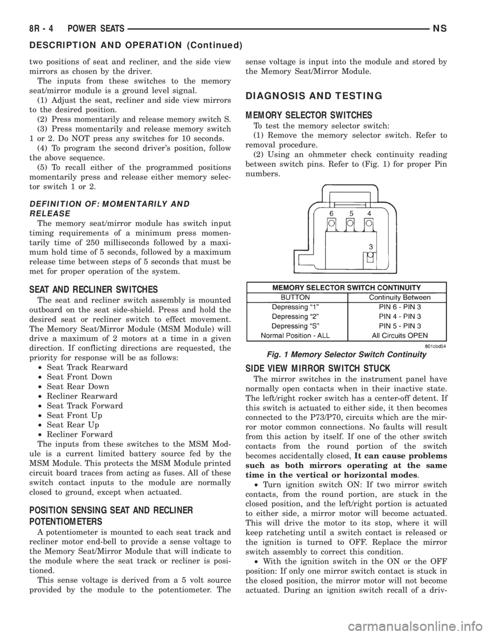
between switch pins. Refer to (Fig. 1) for proper Pin
numbers.
SIDE VIEW MIRROR SWITCH STUCK
The mirror switches in the instrument panel have
normally open contacts when in their inactive state.
The left/right rocker switch has a center-off detent. If
this switch is actuated to either side, it then becomes
connected to the P73/P70, circuits which are the mir-
ror motor common connections. No faults will result
from this action by itself. If one of the other switch
contacts from the round portion of the switch
becomes accidentally closed,It can cause problems
such as both mirrors operating at the same
time in the vertical or horizontal modes.
²Turn ignition switch ON: If two mirror switch
contacts, from the round portion, are stuck in the
closed position, and the left/right portion is actuated
to either side, a mirror motor will become actuated.
This will drive the motor to its stop, where it will
keep ratcheting until a switch contact is released or
the ignition is turned to OFF. Replace the mirror
switch assembly to correct this condition.
²With the ignition switch in the ON or the OFF
position: If only one mirror switch contact is stuck in
the closed position, the mirror motor will not become
actuated. During an ignition switch recall of a driv-
Fig. 1 Memory Selector Switch Continuity
8R - 4 POWER SEATSNS
DESCRIPTION AND OPERATION (Continued)
Page 533 of 1938
er's chosen position, the Memory Seat/Mirror Module
will attempt to drive the mirror motor only if:
²The closed switch contact was the same as the
desired direction
²Until the lack of a signal seen by the module
shuts off the drive to the motor
The Memory Seat/Mirror Module will shut off the
drive to the desired motor. It is possible that a single
stuck contact could place an opposite mirror or direc-
tion into a series connection. This would run the con-
nected motors at approximately half speed. Replace
the mirror switch assembly to correct this condition.
The 25-way connector at the Memory Seat/Mirror
Module (under the driver's seat) and the mirror
mechanization show that both mirrors use the same
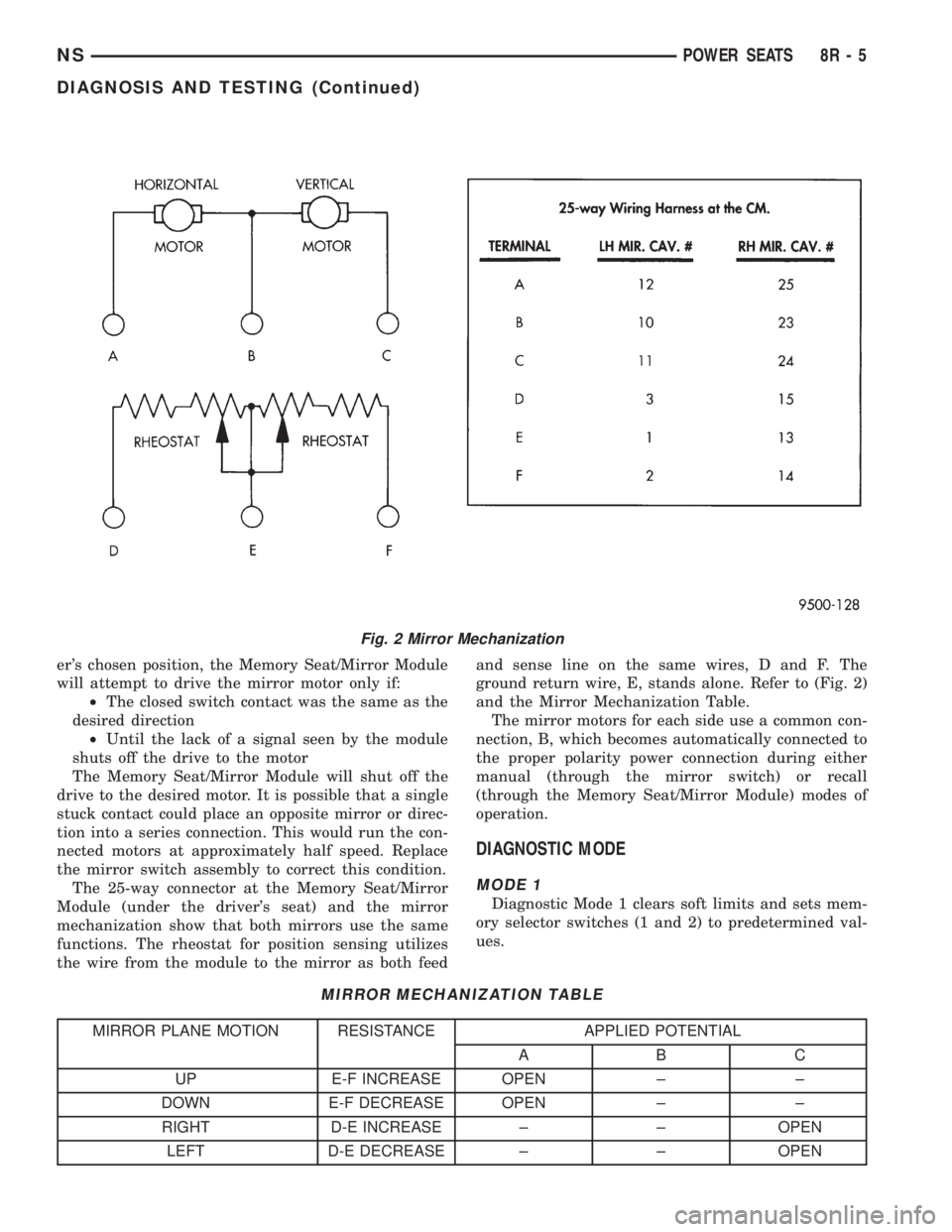
functions. The rheostat for position sensing utilizes
the wire from the module to the mirror as both feedand sense line on the same wires, D and F. The
ground return wire, E, stands alone. Refer to (Fig. 2)
and the Mirror Mechanization Table.
The mirror motors for each side use a common con-
nection, B, which becomes automatically connected to
the proper polarity power connection during either
manual (through the mirror switch) or recall
(through the Memory Seat/Mirror Module) modes of
operation.
DIAGNOSTIC MODE
MODE 1
Diagnostic Mode 1 clears soft limits and sets mem-
ory selector switches (1 and 2) to predetermined val-
ues.
Fig. 2 Mirror Mechanization
MIRROR MECHANIZATION TABLE
MIRROR PLANE MOTION RESISTANCE APPLIED POTENTIAL
AB C
UP E-F INCREASE OPEN ± ±
DOWN E-F DECREASE OPEN ± ±
RIGHT D-E INCREASE ± ± OPEN
LEFT D-E DECREASE ± ± OPEN
NSPOWER SEATS 8R - 5
DIAGNOSIS AND TESTING (Continued)
Page 534 of 1938

ACTIVATION-Press and hold the S and 1 buttons
for 5 seconds to enter diagnostic mode 1. This mode
is exited at the completion of the mode 1 tasks or
upon grounding the RKE input to the Memory Seat/
Mirror Module.
Mode 1 will:
²Clear all soft limits to their default hard limit
values
²Load memory 1 with default settings corre-
sponding to horizontal rearward, front down, rear
down, and recliner rearward positions²Load memory 2 with default settings corre-
sponding to horizontal forward, front up, rear up,
and recliner forward positions
MODE 2
Diagnostic mode 2 provides a way to determine if
the seat/mirror motors and position sensors are con-
nected properly.
ACTIVATION-Press and hold the S and 2 buttons
for 5 seconds to enter diagnostic mode 2. This mode
is exited after 5 seconds of switch inactivity or upon
grounding the RKE input by moving the transmis-
sion out of the PARK position.
Mode 2 will:
²Place the seat and mirror motors at their mid-
point
²When a single axis of seat or mirror motion is
requested by pressing a switch, the corresponding
motor is energized. This tests switch input and motor
output
²When the switch is released, the motor will
automatically return to its original position. If the
corresponding sensor is out of range, then the motor
will not return to its original position. This tests the
integrity of the sensors and motor outputs. Refer to
(Fig. 3), (Fig. 4), (Fig. 5) and (Fig. 6) for module con-
nector call outs.
Fig. 3 Memory Seat/Mirror Module
Fig. 4 Memory Seat/Mirror Module 10-Way Connector
8R - 6 POWER SEATSNS
DIAGNOSIS AND TESTING (Continued)
Page 535 of 1938
CIRCUIT DESCRIPTION
Power to both driver and passenger seats, as well
as power door locks, rear blower, and front fog lamps
(if so equipped), is provided by the A3 circuit through
a 40 amp MAXI-fuse in the Power Distribution Cen-
ter (PDC) under the hood. If all of these devices are
nonfunctional, replace the MAXI-fuse. If the new
MAXI-fuse blows immediately, correct the wiring
short to Ground that could be on any of those afore-
mentioned loads before proceeding further.
Once the power is back ON, if the power seats still
do not work, check the 30 amp circuit breaker that is
located in the driver's seat wiring harness approxi-
mately 10 inches from the 4-way connector. The
power feed circuit to the 30 amp circuit breaker is 14
ga. A3 RD/WT.
Following the 30 amp circuit breaker is a 14 ga.
wire designated as F35 RD that provides power into
the Memory Seat/Mirror Module and is double
crimped with a 14 ga. F35A RD that provides power
to the passenger seat through the 4-way connector.If the power door locks, rear blower, and front fog
lamps (if so equipped) are functional and the seats
are both nonfunctional, repair/replace the open wir-
ing and/or circuit breaker in the driver's seat harness
to correct the condition.
Ensure that the 12 ga. ground wire Z1 BK from
the electrical distribution wiring ground splice into
the 4-way connector is providing ground. The Z1 BK
is double crimped at the seat harness side of the
4-way connector taking a 14 ga. Z1 BK into the
10-way connector (cavity 7) 14 ga. This double crimp
carries a 20 ga. Z1A BK to cavity 3 of the power seat
switch 10-way. If the passenger power seat is func-
tional, and the driver's seat is nonfunctional examine
the circuit F35 RD from the double crimped circuit
breaker connector into the 10-way connector cavity 8
of the control module for continuity. Repair or replace
as necessary. If the driver's seat is still nonfunc-
tional, use a multi-function meter to check the P9 RD
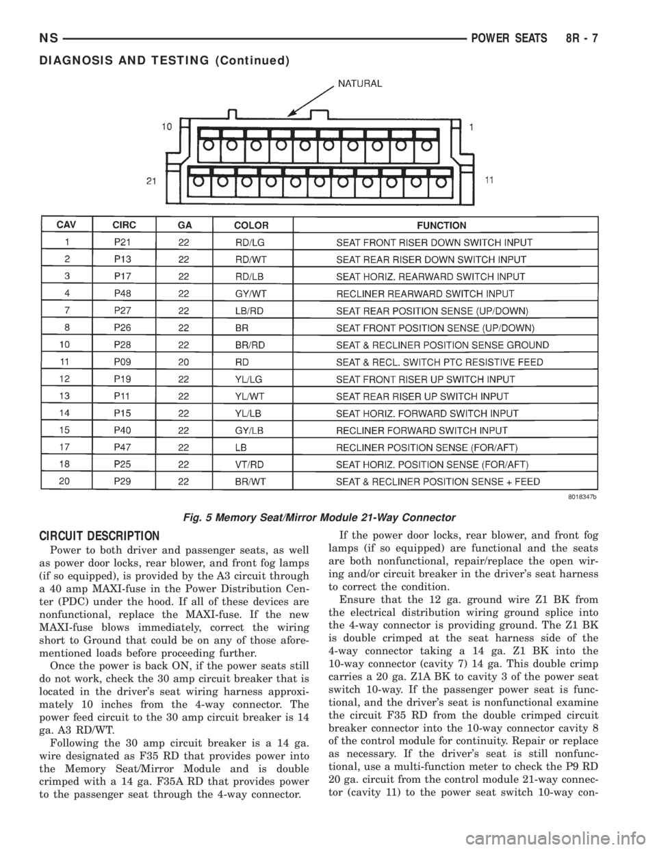
20 ga. circuit from the control module 21-way connec-
tor (cavity 11) to the power seat switch 10-way con-
Fig. 5 Memory Seat/Mirror Module 21-Way Connector
NSPOWER SEATS 8R - 7
DIAGNOSIS AND TESTING (Continued)
Page 536 of 1938

nector (cavity 5)This is a low current battery
feed from the control module that will not illu-
minate a test lamp.
During shipping of the vehicle, an M1 circuit 10
amp fuse (labeled IOD) is temporarily removed from
the PDC in the engine compartment to eliminate
unnecessary battery depletion. However, this fused
circuit being open (that feeds through the electrical
distribution wiring to cavity 16 of the 25-way connec-
tor) will not stop manual seat actuations from taking
place (only recall mode requests) during shipping.
(1) If the memory seat/mirror module does not
respond with a relay click to any seat switch input
(as well as the desired motion) when actuated, pro-
ceed with the following analysis:²Verify power ON F35 and ground Z1 into the
system as indicated above.
²Verify all connectors are mated with the memory
seat/mirror module.
²Place the vehicle gear shift lever in any position
except PARK (causes the Memory Seat/Mirror Mod-
ule to wake-up and provide a position sense voltage
to the seat motor potentiometers and the mirror
rheostat(s). This voltage can be checked at the appro-
priate cavities of the 21 and 25-way connectors.
²Verify the switch connector is mated with the
seat switch on the inside of the outboard side-shield.
²Verify battery voltage at the P9 circuit refer-
enced to the Z1A ground reference (cavity 1) of the
seat switch. If P9 low current battery is not available
Fig. 6 Memory Seat/Mirror Module 25-Way Connector
8R - 8 POWER SEATSNS
DIAGNOSIS AND TESTING (Continued)