brake rotor CHRYSLER VOYAGER 1996 Service Manual
[x] Cancel search | Manufacturer: CHRYSLER, Model Year: 1996, Model line: VOYAGER, Model: CHRYSLER VOYAGER 1996Pages: 1938, PDF Size: 55.84 MB
Page 24 of 1938
DISCONNECT CABLE CLAMPS AS FOLLOWS:
²Disconnect BLACK cable clamp from engine
ground on disabled vehicle.
²When using a Booster vehicle, disconnect
BLACK cable clamp from battery negative terminal.
Disconnect RED cable clamp from battery positive
terminal.
²Disconnect RED cable clamp from battery posi-
tive terminal on disabled vehicle.
TOWING RECOMMENDATIONS
WARNINGS AND CAUTIONS
WARNING: DO NOT ALLOW TOWING ATTACH-
MENT DEVICES TO CONTACT THE FUEL TANK OR
LINES, FUEL LEAK CAN RESULT.
DO NOT LIFT OR TOW VEHICLE BY FRONT OR
REAR BUMPER, OR BUMPER ENERGY ABSORBER
UNITS.
DO NOT GO UNDER A LIFTED VEHICLE IF NOT
SUPPORTED PROPERLY ON SAFETY STANDS.
DO NOT ALLOW PASSENGERS TO RIDE IN A
TOWED VEHICLE.
USE A SAFETY CHAIN THAT IS INDEPENDENT
FROM THE TOWING ATTACHMENT DEVICE.
CAUTION: Do not damage brake lines, exhaust sys-
tem, shock absorbers, sway bars, or any other
under vehicle components when attaching towing
device to vehicle.
Do not attach towing device to front or rear sus-
pension components.
Do not secure vehicle to towing device by the use
of front or rear suspension or steering components.
Remove or secure loose or protruding objects
from a damaged vehicle before towing.
Refer to state and local rules and regulations
before towing a vehicle.
Do not allow weight of towed vehicle to bear on
lower fascia, air dams, or spoilers.
RECOMMENDED TOWING EQUIPMENT
To avoid damage to bumper fascia and air dams
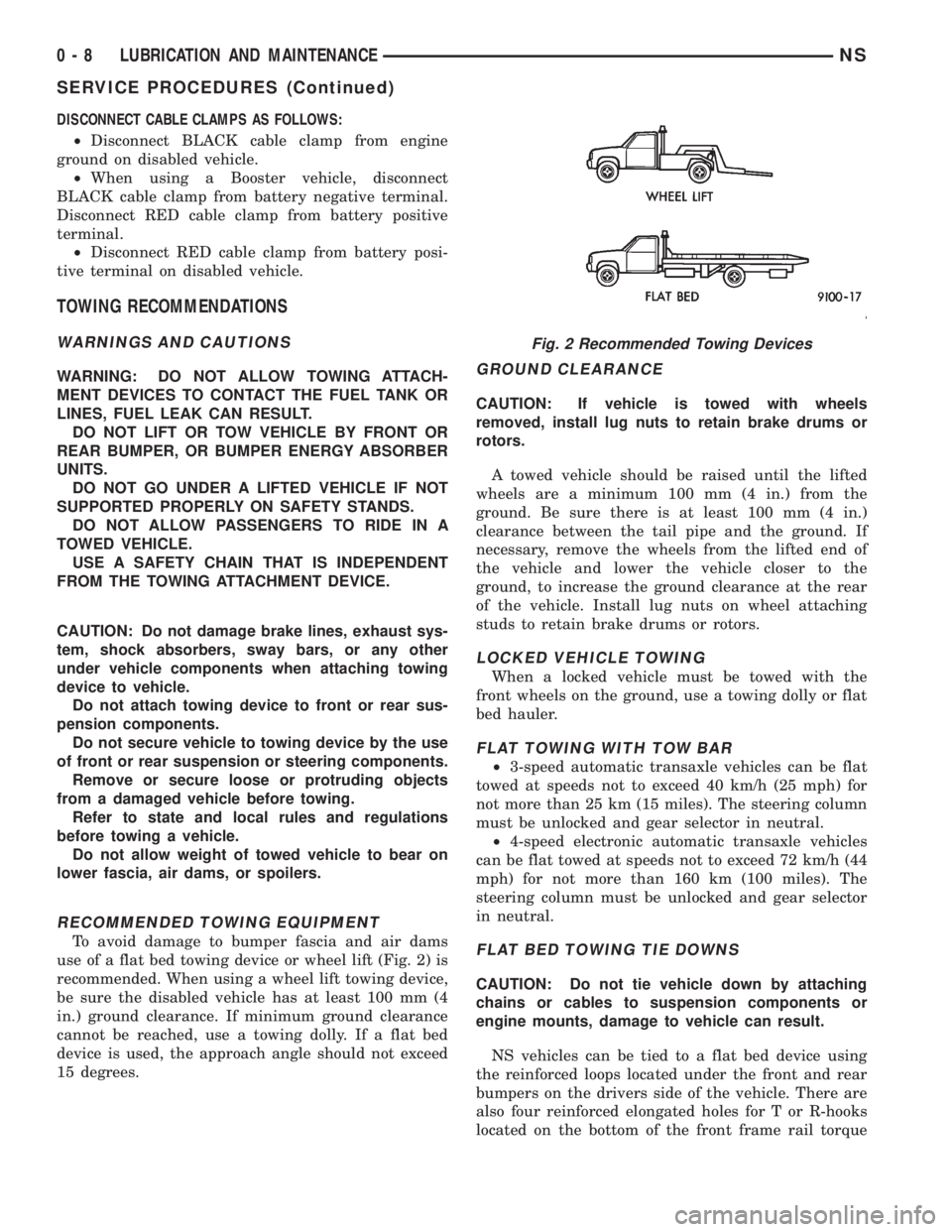
use of a flat bed towing device or wheel lift (Fig. 2) is
recommended. When using a wheel lift towing device,
be sure the disabled vehicle has at least 100 mm (4
in.) ground clearance. If minimum ground clearance
cannot be reached, use a towing dolly. If a flat bed
device is used, the approach angle should not exceed
15 degrees.
GROUND CLEARANCE
CAUTION: If vehicle is towed with wheels
removed, install lug nuts to retain brake drums or
rotors.
A towed vehicle should be raised until the lifted
wheels are a minimum 100 mm (4 in.) from the
ground. Be sure there is at least 100 mm (4 in.)
clearance between the tail pipe and the ground. If
necessary, remove the wheels from the lifted end of
the vehicle and lower the vehicle closer to the
ground, to increase the ground clearance at the rear
of the vehicle. Install lug nuts on wheel attaching
studs to retain brake drums or rotors.
LOCKED VEHICLE TOWING
When a locked vehicle must be towed with the
front wheels on the ground, use a towing dolly or flat
bed hauler.
FLAT TOWING WITH TOW BAR
²3-speed automatic transaxle vehicles can be flat
towed at speeds not to exceed 40 km/h (25 mph) for
not more than 25 km (15 miles). The steering column
must be unlocked and gear selector in neutral.
²4-speed electronic automatic transaxle vehicles
can be flat towed at speeds not to exceed 72 km/h (44
mph) for not more than 160 km (100 miles). The
steering column must be unlocked and gear selector
in neutral.
FLAT BED TOWING TIE DOWNS
CAUTION: Do not tie vehicle down by attaching
chains or cables to suspension components or
engine mounts, damage to vehicle can result.
NS vehicles can be tied to a flat bed device using
the reinforced loops located under the front and rear
bumpers on the drivers side of the vehicle. There are
also four reinforced elongated holes for T or R-hooks
located on the bottom of the front frame rail torque
Fig. 2 Recommended Towing Devices
0 - 8 LUBRICATION AND MAINTENANCENS
SERVICE PROCEDURES (Continued)
Page 31 of 1938
JUMP STARTING, HOISTING AND TOWING
INDEX
page
SERVICE PROCEDURES
TOWING RECOMMENDATIONS............. 5
SERVICE PROCEDURES
TOWING RECOMMENDATIONS
WARNINGS AND CAUTIONS
WARNING: DO NOT ALLOW TOWING ATTACH-
MENT DEVICES TO CONTACT THE FUEL TANK OR
LINES, FUEL LEAK CAN RESULT.
DO NOT LIFT OR TOW VEHICLE BY FRONT OR
REAR BUMPER, OR BUMPER ENERGY ABSORBER
UNITS.
DO NOT GO UNDER A LIFTED VEHICLE IF NOT
SUPPORTED PROPERLY ON SAFETY STANDS.
DO NOT ALLOW PASSENGERS TO RIDE IN A
TOWED VEHICLE.
USE A SAFETY CHAIN THAT IS INDEPENDENT
FROM THE TOWING ATTACHMENT DEVICE.
CAUTION: Do not damage brake lines, exhaust sys-
tem, shock absorbers, sway bars, or any other
under vehicle components when attaching towing
device to vehicle.
Do not attach towing device to front or rear sus-
pension components.
Do not secure vehicle to towing device by the use
of front or rear suspension or steering components.
Remove or secure loose or protruding objects
from a damaged vehicle before towing.
Refer to state and local rules and regulations
before towing a vehicle.
Do not allow weight of towed vehicle to bear on
lower fascia, air dams, or spoilers.
RECOMMENDED TOWING EQUIPMENT
To avoid damage to bumper fascia and air dams
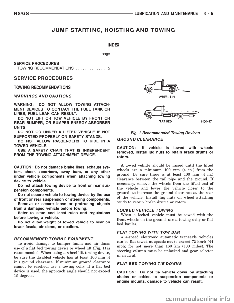
use of a flat bed towing device or wheel lift (Fig. 1) is
recommended. When using a wheel lift towing device,
be sure the disabled vehicle has at least 100 mm (4
in.) ground clearance. If minimum ground clearance
cannot be reached, use a towing dolly. If a flat bed
device is used, the approach angle should not exceed
15 degrees.
GROUND CLEARANCE
CAUTION: If vehicle is towed with wheels
removed, install lug nuts to retain brake drums or
rotors.
A towed vehicle should be raised until the lifted
wheels are a minimum 100 mm (4 in.) from the
ground. Be sure there is at least 100 mm (4 in.)
clearance between the tail pipe and the ground. If
necessary, remove the wheels from the lifted end of
the vehicle and lower the vehicle closer to the
ground, to increase the ground clearance at the rear
of the vehicle. Install lug nuts on wheel attaching
studs to retain brake drums or rotors.
LOCKED VEHICLE TOWING
When a locked vehicle must be towed with the
front wheels on the ground, use a towing dolly or flat
bed hauler.
FLAT TOWING WITH TOW BAR
²4-speed electronic automatic transaxle vehicles
can be flat towed at speeds not to exceed 72 km/h (44
mph) for not more than 160 km (100 miles). The
steering column must be unlocked and gear selector
in neutral.
FLAT BED TOWING TIE DOWNS
CAUTION: Do not tie vehicle down by attaching
chains or cables to suspension components or
engine mounts, damage to vehicle can result.
Fig. 1 Recommended Towing Devices
NS/GSLUBRICATION AND MAINTENANCE 0 - 5
Page 48 of 1938
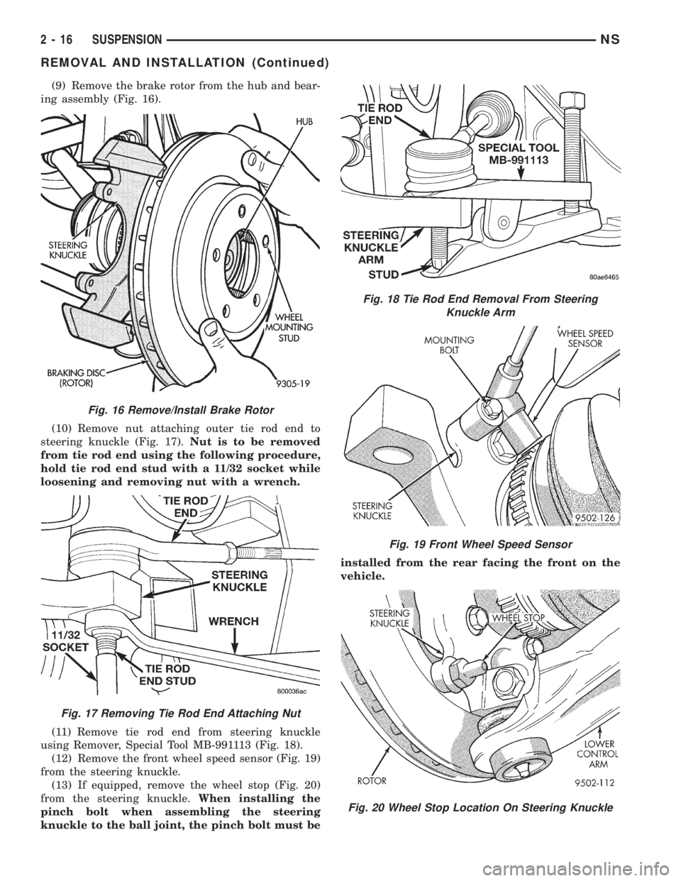
(9) Remove the brake rotor from the hub and bear-
ing assembly (Fig. 16).
(10) Remove nut attaching outer tie rod end to
steering knuckle (Fig. 17).Nut is to be removed
from tie rod end using the following procedure,
hold tie rod end stud with a 11/32 socket while
loosening and removing nut with a wrench.
(11) Remove tie rod end from steering knuckle
using Remover, Special Tool MB-991113 (Fig. 18).
(12) Remove the front wheel speed sensor (Fig. 19)
from the steering knuckle.
(13) If equipped, remove the wheel stop (Fig. 20)
from the steering knuckle.When installing the
pinch bolt when assembling the steering
knuckle to the ball joint, the pinch bolt must beinstalled from the rear facing the front on the
vehicle.
Fig. 16 Remove/Install Brake Rotor
Fig. 17 Removing Tie Rod End Attaching Nut
Fig. 18 Tie Rod End Removal From Steering
Knuckle Arm
Fig. 19 Front Wheel Speed Sensor
Fig. 20 Wheel Stop Location On Steering Knuckle
2 - 16 SUSPENSIONNS
REMOVAL AND INSTALLATION (Continued)
Page 60 of 1938
sequence until all nuts are torqued to half specifica-
tion. Then repeat the tightening sequence to the full
specified torque of 129 N´m (95 ft. lbs.).
(7) Lower vehicle to the ground.
CAUTION: When tightening hub/bearing assembly
to stub shaft retaining nut, do not exceed the max-
imum torque of 244 N´m (180 ft. lbs.).
(8) With vehicle brakes applied to keep vehicle
from moving, torque stub shaft to hub/bearing assem-
bly retaining nut to 244 N´m (180 ft. lbs.).
(9) Check the Toe setting on the vehicle and reset
if not within specifications.
FRONT WHEEL MOUNTING STUDS
REMOVE
CAUTION: If a wheel attaching stud needs to be
replaced in the hub and bearing assembly the studs
CAN NOT be hammered out of the hub flange. If a
stud is removed by hammering it out of the bearing
flange, damage to the hub and bearing assembly
will occur leading to premature bearing failure.
The following procedure and special tools shown
MUST BEused when replacing wheel attaching
studs.
The hub and bearing assembly does not require
removal from the steering knuckle to replace wheel
attaching studs in the hub and bearing assembly.
(1) Raise vehicle on jackstands or centered on a
frame contact type hoist. See Hoisting in the Lubri-
cation and Maintenance section of this manual for
the required lifting procedure to be used for this
vehicle.
(2) Remove the front wheel and tire assembly from
the vehicle.
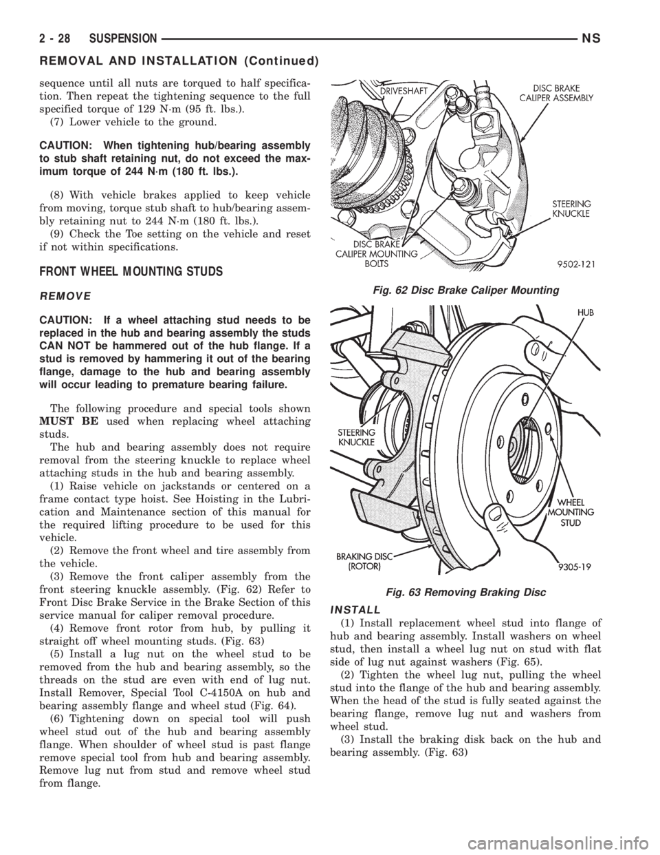
(3) Remove the front caliper assembly from the
front steering knuckle assembly. (Fig. 62) Refer to
Front Disc Brake Service in the Brake Section of this
service manual for caliper removal procedure.
(4) Remove front rotor from hub, by pulling it
straight off wheel mounting studs. (Fig. 63)
(5) Install a lug nut on the wheel stud to be
removed from the hub and bearing assembly, so the
threads on the stud are even with end of lug nut.
Install Remover, Special Tool C-4150A on hub and
bearing assembly flange and wheel stud (Fig. 64).
(6) Tightening down on special tool will push
wheel stud out of the hub and bearing assembly
flange. When shoulder of wheel stud is past flange
remove special tool from hub and bearing assembly.
Remove lug nut from stud and remove wheel stud
from flange.
INSTALL
(1) Install replacement wheel stud into flange of
hub and bearing assembly. Install washers on wheel
stud, then install a wheel lug nut on stud with flat
side of lug nut against washers (Fig. 65).
(2) Tighten the wheel lug nut, pulling the wheel
stud into the flange of the hub and bearing assembly.
When the head of the stud is fully seated against the
bearing flange, remove lug nut and washers from
wheel stud.
(3) Install the braking disk back on the hub and
bearing assembly. (Fig. 63)
Fig. 62 Disc Brake Caliper Mounting
Fig. 63 Removing Braking Disc
2 - 28 SUSPENSIONNS
REMOVAL AND INSTALLATION (Continued)
Page 85 of 1938
BASE BRAKE SYSTEM
INDEX
page page
DESCRIPTION AND OPERATION
CHASSIS TUBES AND HOSES.............. 7
FRONT DISC BRAKE SYSTEM.............. 4
HUB/BEARING REAR WHEEL............... 9
MASTER CYLINDER...................... 7
PARKING BRAKE SYSTEM OPERATION....... 5
POWER BRAKE VACUUM BOOSTER
OPERATION........................... 8
PROPORTIONING VALVES................. 5
REAR DISC BRAKES...................... 5
REAR DRUM BRAKES..................... 5
RED BRAKE WARNING LAMP OPERATION..... 8
STOP LAMP SWITCH...................... 9
DIAGNOSIS AND TESTING
ADJUSTER REAR DRUM BRAKE
(AUTOMATIC)......................... 14
BRAKE FLUID CONTAMINATION............ 19
BRAKE ROTOR......................... 14
BRAKE SYSTEM BASIC DIAGNOSIS GUIDE.... 9
BRAKE SYSTEM DIAGNOSIS CHARTS....... 10
PROPORTIONING VALVES................ 16
RED BRAKE WARNING LAMP TEST......... 19
STOP LAMP SWITCH TEST PROCEDURE..... 19
TRACTION CONTROL LAMP TEST.......... 19
SERVICE PROCEDURES
BLEEDING BASE BRAKE
HYDRAULIC SYSTEM................... 20
BRAKE DRUM MACHINING................ 24
BRAKE TUBE REPAIR PROCEDURE......... 24
MASTER CYLINDER BLEEDING
PROCEDURE......................... 22
MASTER CYLINDER FLUID LEVEL CHECK.... 20
PARK BRAKE AUTO ADJUSTER
MECHANISM RELEASE................. 26
ROTOR MACHINING (FRONT/REAR)......... 22
REMOVAL AND INSTALLATION
BRAKE SUPPORT PLATE (REAR DRUM
BRAKES)............................ 37
FRONT DISC BRAKE CALIPER............. 27
FRONT DISC BRAKE PADS................ 30
FRONT PARK BRAKE CABLE.............. 65
HUB/BEARING.......................... 40
HYDRAULIC BRAKE TUBES AND HOSES..... 58
INTERMEDIATE PARK BRAKE CABLE....... 66
JUNCTION BLOCK....................... 55
LEFT REAR PARK BRAKE CABLE........... 67
MASTER CYLINDER..................... 44
PARK BRAKE PEDAL MECHANISM.......... 58PARK BRAKE SHOES (WITH REAR DISC
BRAKES)............................ 60
PROPORTIONING VALVE (W/ABS BRAKES) . . . 56
PROPORTIONING VALVE
(W/O ABS BRAKES).................... 57
REAR BRAKE DRUM..................... 33
REAR BRAKE WHEEL CYLINDER........... 39
REAR DISC BRAKE CALIPER.............. 28
REAR DISC BRAKE SHOES................ 31
REAR DRUM BRAKE SHOES............... 34
RIGHT REAR PARK BRAKE CABLE......... 66
STOP LAMP SWITCH..................... 69
VACUUM BOOSTER 2.4 LITER ENGINE...... 47
VACUUM BOOSTER 3.0 LITER ENGINE...... 49
VACUUM BOOSTER 3.3/3.8 LITER ENGINE.... 52
WHEEL AND TIRE INSTALLATION........... 27
DISASSEMBLY AND ASSEMBLY
FRONT DISC BRAKE CALIPER............. 71
MASTER CYLINDER BRAKE FLUID LEVEL
SWITCH............................. 71
MASTER CYLINDER FLUID RESERVOIR
FILL TUBE............................ 71
MASTER CYLINDER FLUID RESERVOIR...... 70
MASTER CYLINDER TO POWER BRAKE
BOOSTER VACUUM SEAL............... 69
WHEEL CYLINDER REAR DRUM BRAKE...... 76
CLEANING AND INSPECTION
BRAKE HOSE AND BRAKE LINES
INSPECTION.......................... 78
FRONT DISC BRAKE PAD LINING
INSPECTION.......................... 76
REAR DISC BRAKES..................... 76
REAR DRUM BRAKE SHOE LINING
INSPECTION.......................... 77
REAR DRUM BRAKE WHEEL CYLINDER...... 78
REAR WHEEL HUB AND BEARING
ASSEMBLY........................... 78
ADJUSTMENTS
PARK BRAKE CABLE ADJUSTMENT......... 81
PARK BRAKE SHOES (WITH REAR DISC
BRAKES)............................ 79
PROPORTIONING VALVE
(HEIGHT SENSING).................... 81
REAR DRUM BRAKE SHOE ADJUSTMENT.... 79
STOP LAMP SWITCH..................... 78
SPECIFICATIONS
BRAKE ACTUATION SYSTEM.............. 83
BRAKE FASTENER TORQUE
SPECIFICATIONS...................... 83
NSBRAKES 5 - 3
Page 86 of 1938
BRAKE FLUID.......................... 82
VEHICLE BRAKE SYSTEM COMPONENT
SPECIFICATIONS...................... 82SPECIAL TOOLS
BASE BRAKES.......................... 84
DESCRIPTION AND OPERATION
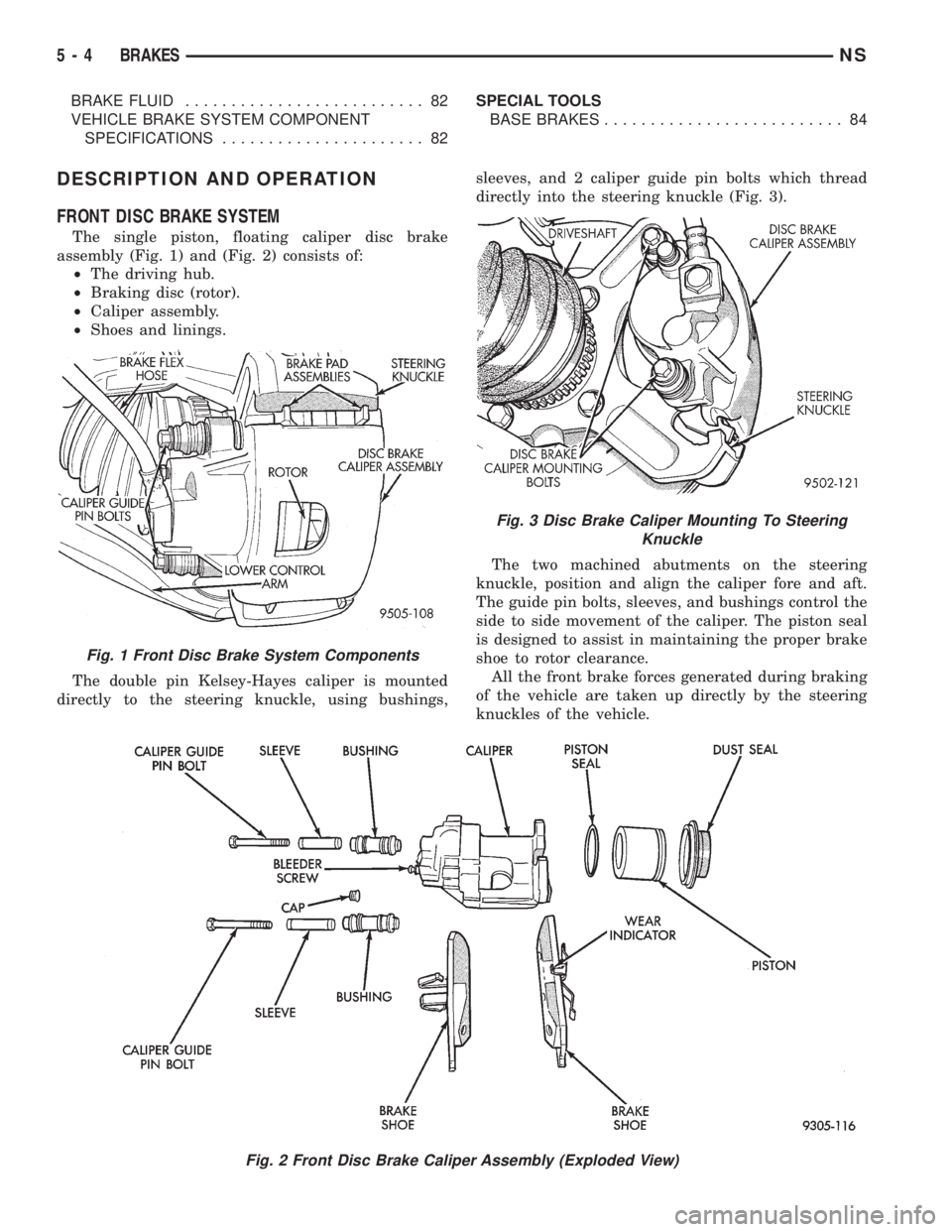
FRONT DISC BRAKE SYSTEM
The single piston, floating caliper disc brake
assembly (Fig. 1) and (Fig. 2) consists of:
²The driving hub.
²Braking disc (rotor).
²Caliper assembly.
²Shoes and linings.
The double pin Kelsey-Hayes caliper is mounted
directly to the steering knuckle, using bushings,sleeves, and 2 caliper guide pin bolts which thread
directly into the steering knuckle (Fig. 3).
The two machined abutments on the steering
knuckle, position and align the caliper fore and aft.
The guide pin bolts, sleeves, and bushings control the
side to side movement of the caliper. The piston seal
is designed to assist in maintaining the proper brake
shoe to rotor clearance.
All the front brake forces generated during braking
of the vehicle are taken up directly by the steering
knuckles of the vehicle.
Fig. 2 Front Disc Brake Caliper Assembly (Exploded View)
Fig. 1 Front Disc Brake System Components
Fig. 3 Disc Brake Caliper Mounting To Steering
Knuckle
5 - 4 BRAKESNS
Page 87 of 1938
The caliper is a one piece casting with the inboard
side containing a single piston cylinder bore.
The phenolic piston is 60 mm (2.36 inch) in diam-
eter.
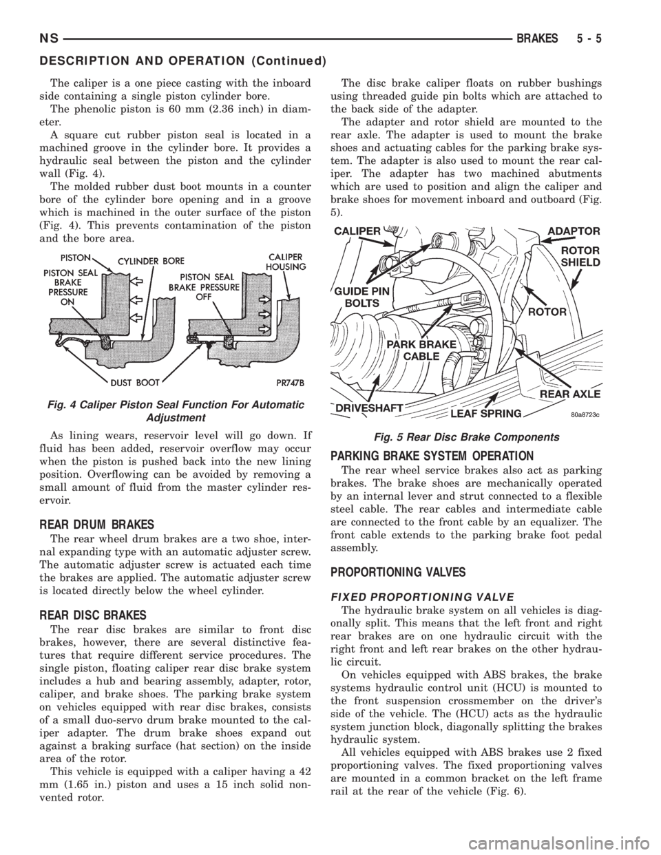
A square cut rubber piston seal is located in a
machined groove in the cylinder bore. It provides a
hydraulic seal between the piston and the cylinder
wall (Fig. 4).
The molded rubber dust boot mounts in a counter
bore of the cylinder bore opening and in a groove
which is machined in the outer surface of the piston
(Fig. 4). This prevents contamination of the piston
and the bore area.
As lining wears, reservoir level will go down. If
fluid has been added, reservoir overflow may occur
when the piston is pushed back into the new lining
position. Overflowing can be avoided by removing a
small amount of fluid from the master cylinder res-
ervoir.
REAR DRUM BRAKES
The rear wheel drum brakes are a two shoe, inter-
nal expanding type with an automatic adjuster screw.
The automatic adjuster screw is actuated each time
the brakes are applied. The automatic adjuster screw
is located directly below the wheel cylinder.
REAR DISC BRAKES
The rear disc brakes are similar to front disc
brakes, however, there are several distinctive fea-
tures that require different service procedures. The
single piston, floating caliper rear disc brake system
includes a hub and bearing assembly, adapter, rotor,
caliper, and brake shoes. The parking brake system
on vehicles equipped with rear disc brakes, consists
of a small duo-servo drum brake mounted to the cal-
iper adapter. The drum brake shoes expand out
against a braking surface (hat section) on the inside
area of the rotor.
This vehicle is equipped with a caliper having a 42
mm (1.65 in.) piston and uses a 15 inch solid non-
vented rotor.The disc brake caliper floats on rubber bushings
using threaded guide pin bolts which are attached to
the back side of the adapter.
The adapter and rotor shield are mounted to the
rear axle. The adapter is used to mount the brake
shoes and actuating cables for the parking brake sys-
tem. The adapter is also used to mount the rear cal-
iper. The adapter has two machined abutments
which are used to position and align the caliper and
brake shoes for movement inboard and outboard (Fig.
5).
PARKING BRAKE SYSTEM OPERATION
The rear wheel service brakes also act as parking
brakes. The brake shoes are mechanically operated
by an internal lever and strut connected to a flexible
steel cable. The rear cables and intermediate cable
are connected to the front cable by an equalizer. The
front cable extends to the parking brake foot pedal
assembly.
PROPORTIONING VALVES
FIXED PROPORTIONING VALVE
The hydraulic brake system on all vehicles is diag-
onally split. This means that the left front and right
rear brakes are on one hydraulic circuit with the
right front and left rear brakes on the other hydrau-
lic circuit.
On vehicles equipped with ABS brakes, the brake
systems hydraulic control unit (HCU) is mounted to
the front suspension crossmember on the driver's
side of the vehicle. The (HCU) acts as the hydraulic
system junction block, diagonally splitting the brakes
hydraulic system.
All vehicles equipped with ABS brakes use 2 fixed
proportioning valves. The fixed proportioning valves
are mounted in a common bracket on the left frame
rail at the rear of the vehicle (Fig. 6).
Fig. 4 Caliper Piston Seal Function For Automatic
Adjustment
Fig. 5 Rear Disc Brake Components
NSBRAKES 5 - 5
DESCRIPTION AND OPERATION (Continued)
Page 96 of 1938
ADJUSTER REAR DRUM BRAKE (AUTOMATIC)
The rear drum brakes on this vehicle automatically
adjust, when required, during the normal operation
of the vehicle every time the brakes are applied. Use
the following procedure to test the operation of the
automatic adjuster.
Place the vehicle on a hoist with a helper in the
driver's seat to apply the brakes. Remove the access
plug from the adjustment hole in each brake support
plate to provide visual access of the brake adjuster
star wheel.
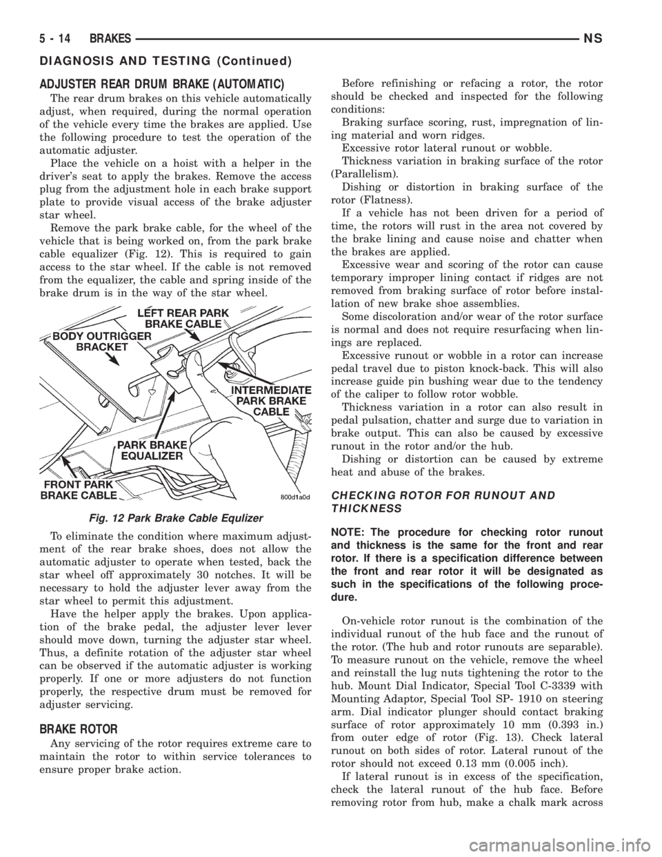
Remove the park brake cable, for the wheel of the
vehicle that is being worked on, from the park brake
cable equalizer (Fig. 12). This is required to gain
access to the star wheel. If the cable is not removed
from the equalizer, the cable and spring inside of the
brake drum is in the way of the star wheel.
To eliminate the condition where maximum adjust-
ment of the rear brake shoes, does not allow the
automatic adjuster to operate when tested, back the
star wheel off approximately 30 notches. It will be
necessary to hold the adjuster lever away from the
star wheel to permit this adjustment.
Have the helper apply the brakes. Upon applica-
tion of the brake pedal, the adjuster lever lever
should move down, turning the adjuster star wheel.
Thus, a definite rotation of the adjuster star wheel
can be observed if the automatic adjuster is working
properly. If one or more adjusters do not function
properly, the respective drum must be removed for
adjuster servicing.
BRAKE ROTOR
Any servicing of the rotor requires extreme care to
maintain the rotor to within service tolerances to
ensure proper brake action.Before refinishing or refacing a rotor, the rotor
should be checked and inspected for the following
conditions:
Braking surface scoring, rust, impregnation of lin-
ing material and worn ridges.
Excessive rotor lateral runout or wobble.
Thickness variation in braking surface of the rotor
(Parallelism).
Dishing or distortion in braking surface of the
rotor (Flatness).
If a vehicle has not been driven for a period of
time, the rotors will rust in the area not covered by
the brake lining and cause noise and chatter when
the brakes are applied.
Excessive wear and scoring of the rotor can cause
temporary improper lining contact if ridges are not
removed from braking surface of rotor before instal-
lation of new brake shoe assemblies.
Some discoloration and/or wear of the rotor surface
is normal and does not require resurfacing when lin-
ings are replaced.
Excessive runout or wobble in a rotor can increase
pedal travel due to piston knock-back. This will also
increase guide pin bushing wear due to the tendency
of the caliper to follow rotor wobble.
Thickness variation in a rotor can also result in
pedal pulsation, chatter and surge due to variation in
brake output. This can also be caused by excessive
runout in the rotor and/or the hub.
Dishing or distortion can be caused by extreme
heat and abuse of the brakes.
CHECKING ROTOR FOR RUNOUT AND
THICKNESS
NOTE: The procedure for checking rotor runout
and thickness is the same for the front and rear
rotor. If there is a specification difference between
the front and rear rotor it will be designated as
such in the specifications of the following proce-
dure.
On-vehicle rotor runout is the combination of the
individual runout of the hub face and the runout of
the rotor. (The hub and rotor runouts are separable).
To measure runout on the vehicle, remove the wheel
and reinstall the lug nuts tightening the rotor to the
hub. Mount Dial Indicator, Special Tool C-3339 with
Mounting Adaptor, Special Tool SP- 1910 on steering
arm. Dial indicator plunger should contact braking
surface of rotor approximately 10 mm (0.393 in.)
from outer edge of rotor (Fig. 13). Check lateral
runout on both sides of rotor. Lateral runout of the
rotor should not exceed 0.13 mm (0.005 inch).
If lateral runout is in excess of the specification,
check the lateral runout of the hub face. Before
removing rotor from hub, make a chalk mark across
Fig. 12 Park Brake Cable Equlizer
5 - 14 BRAKESNS
DIAGNOSIS AND TESTING (Continued)
Page 97 of 1938
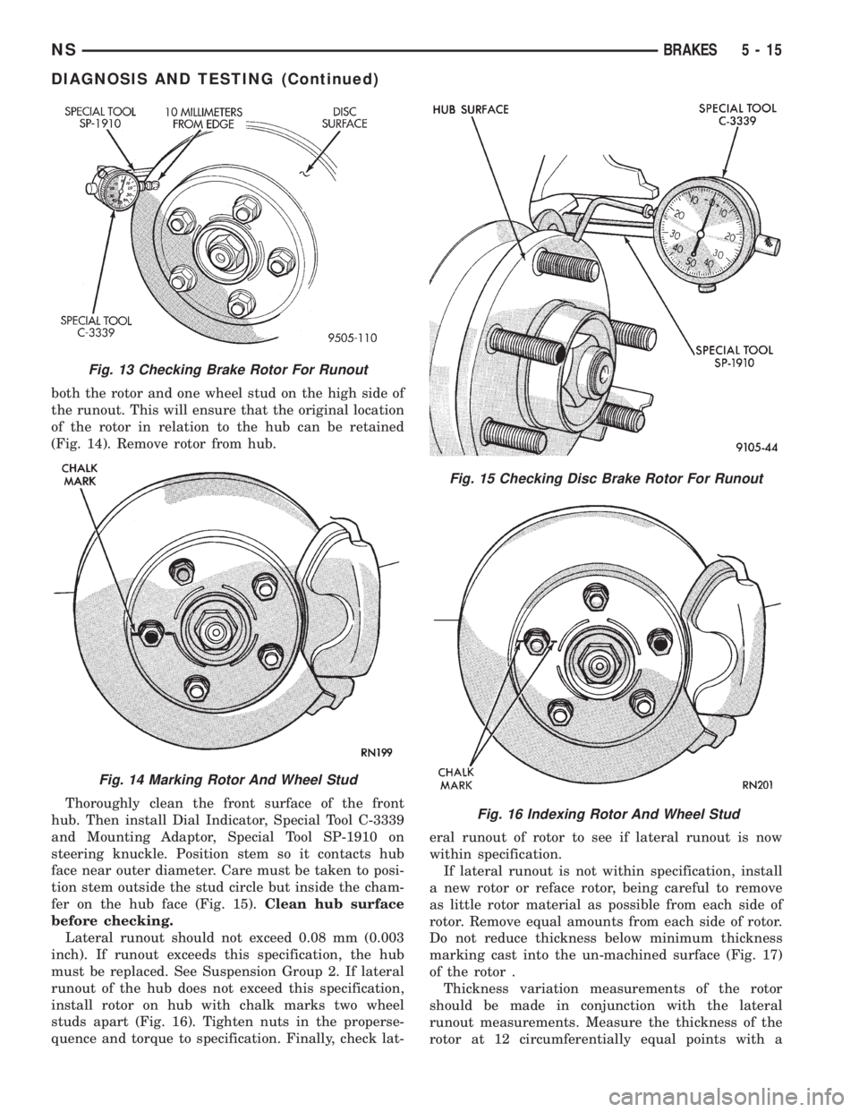
both the rotor and one wheel stud on the high side of
the runout. This will ensure that the original location
of the rotor in relation to the hub can be retained
(Fig. 14). Remove rotor from hub.
Thoroughly clean the front surface of the front
hub. Then install Dial Indicator, Special Tool C-3339
and Mounting Adaptor, Special Tool SP-1910 on
steering knuckle. Position stem so it contacts hub
face near outer diameter. Care must be taken to posi-
tion stem outside the stud circle but inside the cham-
fer on the hub face (Fig. 15).Clean hub surface
before checking.
Lateral runout should not exceed 0.08 mm (0.003
inch). If runout exceeds this specification, the hub
must be replaced. See Suspension Group 2. If lateral
runout of the hub does not exceed this specification,
install rotor on hub with chalk marks two wheel
studs apart (Fig. 16). Tighten nuts in the properse-
quence and torque to specification. Finally, check lat-eral runout of rotor to see if lateral runout is now
within specification.
If lateral runout is not within specification, install
a new rotor or reface rotor, being careful to remove
as little rotor material as possible from each side of
rotor. Remove equal amounts from each side of rotor.
Do not reduce thickness below minimum thickness
marking cast into the un-machined surface (Fig. 17)
of the rotor .
Thickness variation measurements of the rotor
should be made in conjunction with the lateral
runout measurements. Measure the thickness of the
rotor at 12 circumferentially equal points with a
Fig. 16 Indexing Rotor And Wheel Stud
Fig. 13 Checking Brake Rotor For Runout
Fig. 14 Marking Rotor And Wheel Stud
Fig. 15 Checking Disc Brake Rotor For Runout
NSBRAKES 5 - 15
DIAGNOSIS AND TESTING (Continued)
Page 98 of 1938
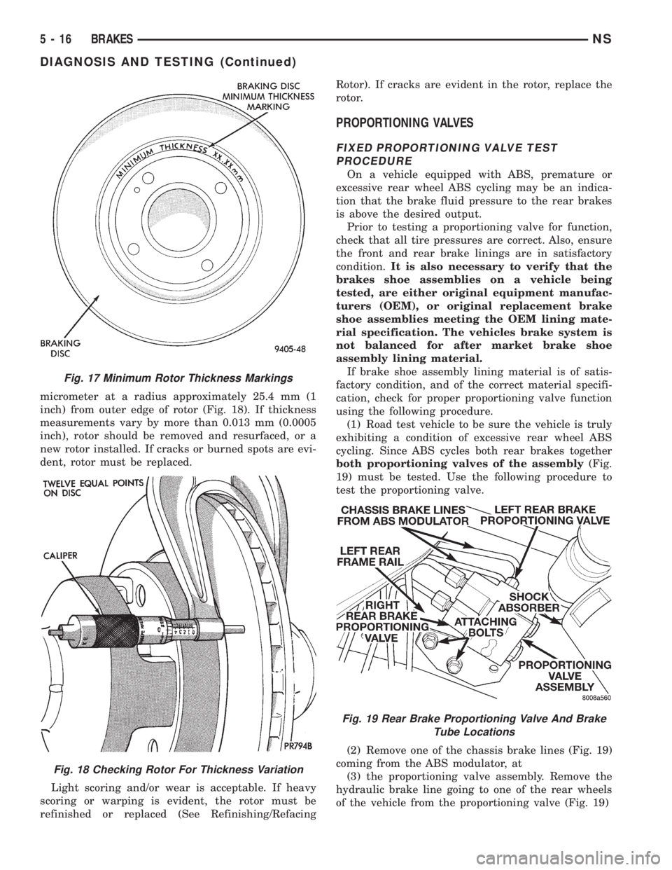
micrometer at a radius approximately 25.4 mm (1
inch) from outer edge of rotor (Fig. 18). If thickness
measurements vary by more than 0.013 mm (0.0005
inch), rotor should be removed and resurfaced, or a
new rotor installed. If cracks or burned spots are evi-
dent, rotor must be replaced.
Light scoring and/or wear is acceptable. If heavy
scoring or warping is evident, the rotor must be
refinished or replaced (See Refinishing/RefacingRotor). If cracks are evident in the rotor, replace the
rotor.
PROPORTIONING VALVES
FIXED PROPORTIONING VALVE TEST
PROCEDURE
On a vehicle equipped with ABS, premature or
excessive rear wheel ABS cycling may be an indica-
tion that the brake fluid pressure to the rear brakes
is above the desired output.
Prior to testing a proportioning valve for function,
check that all tire pressures are correct. Also, ensure
the front and rear brake linings are in satisfactory
condition.It is also necessary to verify that the
brakes shoe assemblies on a vehicle being
tested, are either original equipment manufac-
turers (OEM), or original replacement brake
shoe assemblies meeting the OEM lining mate-
rial specification. The vehicles brake system is
not balanced for after market brake shoe
assembly lining material.
If brake shoe assembly lining material is of satis-
factory condition, and of the correct material specifi-
cation, check for proper proportioning valve function
using the following procedure.
(1) Road test vehicle to be sure the vehicle is truly
exhibiting a condition of excessive rear wheel ABS
cycling. Since ABS cycles both rear brakes together
both proportioning valves of the assembly(Fig.
19) must be tested. Use the following procedure to
test the proportioning valve.
(2) Remove one of the chassis brake lines (Fig. 19)
coming from the ABS modulator, at
(3) the proportioning valve assembly. Remove the
hydraulic brake line going to one of the rear wheels
of the vehicle from the proportioning valve (Fig. 19)
Fig. 17 Minimum Rotor Thickness Markings
Fig. 18 Checking Rotor For Thickness Variation
Fig. 19 Rear Brake Proportioning Valve And Brake
Tube Locations
5 - 16 BRAKESNS
DIAGNOSIS AND TESTING (Continued)