engine vacuum CHRYSLER VOYAGER 2000 Diagnostic Manual
[x] Cancel search | Manufacturer: CHRYSLER, Model Year: 2000, Model line: VOYAGER, Model: CHRYSLER VOYAGER 2000Pages: 364, PDF Size: 2.17 MB
Page 3 of 364
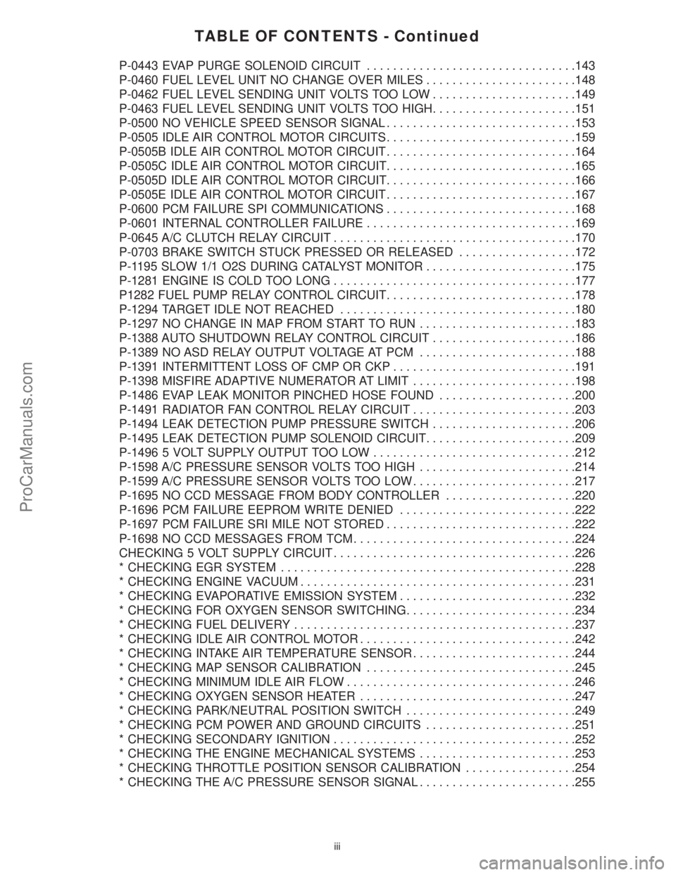
TABLE OF CONTENTS - Continued
P-0443 EVAP PURGE SOLENOID CIRCUIT................................143
P-0460 FUEL LEVEL UNIT NO CHANGE OVER MILES.......................148
P-0462 FUEL LEVEL SENDING UNIT VOLTS TOO LOW......................149
P-0463 FUEL LEVEL SENDING UNIT VOLTS TOO HIGH......................151
P-0500 NO VEHICLE SPEED SENSOR SIGNAL.............................153
P-0505 IDLE AIR CONTROL MOTOR CIRCUITS.............................159
P-0505B IDLE AIR CONTROL MOTOR CIRCUIT.............................164
P-0505C IDLE AIR CONTROL MOTOR CIRCUIT.............................165
P-0505D IDLE AIR CONTROL MOTOR CIRCUIT.............................166
P-0505E IDLE AIR CONTROL MOTOR CIRCUIT.............................167
P-0600 PCM FAILURE SPI COMMUNICATIONS.............................168
P-0601 INTERNAL CONTROLLER FAILURE................................169
P-0645 A/C CLUTCH RELAY CIRCUIT.....................................170
P-0703 BRAKE SWITCH STUCK PRESSED OR RELEASED..................172
P-1195 SLOW 1/1 O2S DURING CATALYST MONITOR.......................175
P-1281 ENGINE IS COLD TOO LONG.....................................177
P1282 FUEL PUMP RELAY CONTROL CIRCUIT.............................178
P-1294 TARGET IDLE NOT REACHED....................................180
P-1297 NO CHANGE IN MAP FROM START TO RUN........................183
P-1388 AUTO SHUTDOWN RELAY CONTROL CIRCUIT......................186
P-1389 NO ASD RELAY OUTPUT VOLTAGE AT PCM........................188
P-1391 INTERMITTENT LOSS OF CMP OR CKP............................191
P-1398 MISFIRE ADAPTIVE NUMERATOR AT LIMIT.........................198
P-1486 EVAP LEAK MONITOR PINCHED HOSE FOUND.....................200
P-1491 RADIATOR FAN CONTROL RELAY CIRCUIT.........................203
P-1494 LEAK DETECTION PUMP PRESSURE SWITCH......................206
P-1495 LEAK DETECTION PUMP SOLENOID CIRCUIT.......................209
P-1496 5 VOLT SUPPLY OUTPUT TOO LOW...............................212
P-1598 A/C PRESSURE SENSOR VOLTS TOO HIGH........................214
P-1599 A/C PRESSURE SENSOR VOLTS TOO LOW.........................217
P-1695 NO CCD MESSAGE FROM BODY CONTROLLER....................220
P-1696 PCM FAILURE EEPROM WRITE DENIED...........................222
P-1697 PCM FAILURE SRI MILE NOT STORED.............................222
P-1698 NO CCD MESSAGES FROM TCM..................................224
CHECKING 5 VOLT SUPPLY CIRCUIT.....................................226
* CHECKING EGR SYSTEM.............................................228
* CHECKING ENGINE VACUUM..........................................231
* CHECKING EVAPORATIVE EMISSION SYSTEM...........................232
* CHECKING FOR OXYGEN SENSOR SWITCHING..........................234
* CHECKING FUEL DELIVERY...........................................237
* CHECKING IDLE AIR CONTROL MOTOR.................................242
* CHECKING INTAKE AIR TEMPERATURE SENSOR.........................244
* CHECKING MAP SENSOR CALIBRATION................................245
* CHECKING MINIMUM IDLE AIR FLOW...................................246
* CHECKING OXYGEN SENSOR HEATER.................................247
* CHECKING PARK/NEUTRAL POSITION SWITCH..........................249
* CHECKING PCM POWER AND GROUND CIRCUITS.......................251
* CHECKING SECONDARY IGNITION.....................................252
* CHECKING THE ENGINE MECHANICAL SYSTEMS........................253
* CHECKING THROTTLE POSITION SENSOR CALIBRATION.................254
* CHECKING THE A/C PRESSURE SENSOR SIGNAL........................255
iii
ProCarManuals.com
Page 10 of 364
3.2.3 OTHER CONTROLS
CHARGING SYSTEM
The charging system is turned on when the
engine is started and ASD relay energized. When
the ASD relay is on, ASD output voltage is supplied
to the ASD sense circuit at the PCM. This voltage is
connected in some cases, through the PCM and
supplied to one of the generator field terminals
(Gen Source +). All others, the Gen field is con-
nected directly to the ASD output voltage. The
amount of current produced by the generator is
controlled by the Electronic Voltage Regulator
(EVR) circuitry, in the PCM. A battery temperature
sensor, located either in the battery tray, using the
ambient sensor, or in the PCM itself, is used to
sense battery temperature. This temperature along
with sensed line voltage, is used by the PCM to vary
the battery charging rate. This is done by cycling
the ground path to the other generator field termi-
nal (Gen field driver).
SPEED CONTROL SYSTEM
The PCM controls vehicle speed by operation of
the speed control servo vacuum and vent solenoids.
Energizing the vacuum solenoid applies vacuum to
the servo to increase throttle position. Operation of
the vent solenoid slowly releases the vacuum allow-
ing throttle position to decrease. A special dump
solenoid allows immediate release of throttle posi-
tion caused by braking, cruise control switch turned
off, shifting into neutral, excessive RPM (tires spin-
ning) or ignition key off.
3.2.4 PCM OPERATING MODES
As input signals to the powertrain control module
(PCM) change, the PCM adjusts its response to
output devices. For example, the PCM must calcu-
late a different injector pulse width and ignition
timing for idle than it does for wide open throttle.
There are several different modes of operation that
determine how the PCM responds to the various
input signals.
There are two types of engine control operation:
open loopandclosed loop.
In open loop operation, the PCM receives input
signals and responds according to preset program-
ming. Inputs from the heated oxygen sensors are
not monitored.
In closed loop operation, the PCM monitors the
inputs from the heated oxygen sensors. This input
indicates to the PCM whether or not the calculated
injector pulse width results in the ideal air-fuel
ratio of 14.7 parts air to 1 part fuel. By monitoring
the exhaust oxygen content through the oxygen
sensor, the PCM can fine tune injector pulse width.
Fine tuning injector pulse width allows the PCM toachieve the lowest emission levels while maintain-
ing optimum fuel economy.
The engine start-up (crank), engine warm-up,
and wide open throttle modes are open loop modes.
Under most operating conditions, closed loop modes
occur with the engine at operating temperature.
IGNITION SWITCH ON (ENGINE OFF) MODE
When the ignition switch activates the fuel injec-
tion system, the following actions occur:
1. The PCM determines atmospheric air pressure
from the MAP sensor input to determine basic
fuel strategy.
2. The PCM monitors the engine coolant tempera-
ture sensor and throttle position sensor input.
The PCM modifies fuel strategy based on this
input.
When the key is in the ªonº position and the
engine is not running (zero rpm), the auto shut-
down relay and fuel pump relay are not energized.
Therefore, voltage is not supplied to the fuel pump,
ignition coil, and fuel injectors.
Engine Start-up Mode -This is an open loop
mode. The following actions occur when the starter
motor is engaged:
1. The auto shutdown and fuel pump relays are
energized. If the PCM does not receive the cam-
shaft and crankshaft signal within approxi-
mately one second, these relays are de-
energized.
2. The PCM energizes all fuel injectors until it
determines crankshaft position from the cam-
shaft and crankshaft signals. The PCM deter-
mines crankshaft position within one engine
revolution. After the crankshaft position has
been determined, the PCM energizes the fuel
injectors in sequence. The PCM adjusts the in-
jector pulse width and synchronizes the fuel
injectors by controlling the fuel injectors' ground
paths.
3. Once the engine idles within 64 rpm of its target
engine speed, the PCM compares the current
MAP sensor value with the value received dur-
ing the ignition switch on (zero rpm) mode. A
diagnostic trouble code is written to PCM mem-
ory if a minimum difference between the two
values is not found.
Once the auto shutdown and fuel pump relays
have been energized, the PCM determines the fuel
injector pulse width based on the following:
± engine coolant temperature
± manifold absolute pressure
± intake air temperature
± engine revolutions
± throttle position
4
GENERAL INFORMATION
ProCarManuals.com
Page 11 of 364
The PCM determines the spark advance based on
the following:
± engine coolant temperature
± crankshaft position
± camshaft position
± intake air temperature
± manifold absolute pressure
± throttle position
Engine Warm-Up Mode -This is an open loop-
mode. The PCM adjusts injector pulse width and
controls injector synchronization by controlling the
fuel injectors' ground paths. The PCM adjusts igni-
tion timing and engine idle speed. The PCM adjusts
the idle speed by controlling the idle air control
motor and spark advance.
Cruise or Idle Mode -When the engine is at
normal operating temperature, this is a closed loop
mode.
Acceleration Mode -This is a closed loop mode.
The PCM recognizes an increase in throttle position
and a decrease in manifold vacuum as engine load
increases. In response, the PCM increases the in-
jector pulse width to meet the increased load. The
A/C compressor may be de-energized for a short
period of time.
Deceleration -This is a closed loop mode. The
PCM recognizes a decrease in throttle position and
an increase in manifold vacuum as engine load
decreases. In response, the PCM decreases the
injector pulse width to meet the decreased load.
Full injector shut off may be obtained during high
speed deceleration.
Wide Open Throttle Mode -This is an open
loop mode. The throttle position sensor notifies the
PCM of a wide open throttle condition. Once a wide
open throttle is sensed, the PCM de-energizes the
A/C compressor clutch relay for 15 seconds.
3.2.5 NON-MONITORED CIRCUITS
The PCM does not monitor the following circuits,
systems, and conditions even though they could
have malfunctions that result in driveability prob-
lems. A diagnostic code may not be displayed for the
following conditions. However, problems with these
systems may cause a diagnostic code to be displayed
for other systems. For example, a fuel pressure
problem will not register a diagnostic code directly,
but could cause a rich or lean condition. This could
cause an oxygen sensor, fuel system, or misfire
monitor trouble code to be stored in the PCM.
Engine Timing -The PCM cannot detect an
incorrectly indexed timing chain, camshaft
sprocket, or crankshaft sprocket. The PCM also
cannot detect an incorrectly indexed distributor.(*)
Fuel Pressure -Fuel pressure is controlled by
the fuel pressure regulator. The PCM cannot detecta clogged fuel pump inlet filter, clogged in-line filter,
or a pinched fuel supply.(*)
Fuel Injectors -The PCM cannot detect if a fuel
injector is clogged, the pintle is sticking, or the
wrong injectors are installed.(*)
Fuel Requirements -Poor quality gasoline can
cause problems such as hard starting, stalling, and
stumble. Use of methanol-gasoline blends may re-
sult in starting and driveability problems. See indi-
vidual symptoms and their definitions in Section
6.0 (Glossary of Terms)
PCM Grounds -The PCM cannot detect a poor
system ground. However, a diagnostic trouble code
may be stored in the PCM as a result of this
condition.
Throttle Body Air Flow -The PCM cannot
detect a clogged or restricted air cleaner inlet or
filter element.(*)
Exhaust System -The PCM cannot detect a
plugged, restricted, or leaking exhaust system.(*)
Cylinder Compression -The PCM cannot de-
tect uneven, low, or high engine cylinder compres-
sion.(*)
Excessive Oil Consumption -Although the
PCM monitors the exhaust stream oxygen content
through the oxygen sensor when the system is in a
closed loop, it cannot determine excessive oil con-
sumption.
(*)NOTE: ANY OF THESE CONDITIONS
COULD RESULT IN A RICH OR LEAN
CONDITION CAUSING AN OXYGEN SENSOR
TROUBLE CODE TO BE STORED IN THE
PCM, OR THE VEHICLE MAY EXHIBIT ONE
OR MORE OF THE DRIVEABILITY
SYMPTOMS LISTED IN THE TABLE OF
CONTENTS.
3.2.6 SKIS OVERVIEW
The Sentry Key Immobilizer System (SKIS) is an
immobilizer system design to prevent unauthorized
vehicle operation. The system consists of a Sentry
Key Immobilizer Module (SKIM), ignition key(s)
equipped with a transponder chip and engine con-
troller. When the ignition switch is turned on, the
SKIM interrogates the ignition key. If the ignition
key is ``Valid'', the SKIM sends a CCD Bus message
to the engine controller indicating the presence of a
valid igntion key. Upon receiving a ``Valid'' key
signal the PCM will allow the engine to continue to
operate.
3.2.7 SKIM ON-BOARD DIAGNOSTICS
The SKIM has been programmed to transmit and
monitor many different coded messages as well as
CCD Bus messages. This monitoring is called ``On
Board Diagnosis''.
5
GENERAL INFORMATION
ProCarManuals.com
Page 19 of 364

4.3.3 ELECTRONIC PINION FACTOR
WARNING
The pinion factor must be set for all new trans-
mission control modules. If the pinion factor is not
set or if it is set incorrectly, any speed-related
accessories will not operate or will operate inaccu-
rately. This includes the speedometer, speed con-
trol, rolling door locks, and other devices that are
operated by the powertrain and body control mod-
ules. For instructions on setting the pinion factor,
see the appropriate transmission diagnostic man-
ual or the service manual.
5.0 RECOMMENDED TOOLS
AND EQUIPMENT
DRBIIIt(diagnostic readout box) scan tool
fuel pressure adapter (C-6631) or #6539
fuel pressure kit (C-4799-B) or #5069
fuel release hose (C-4799-1)
MinAir flow fitting #6457
jumper wires
ohmmeter
oscilloscope
vacuum gauge
voltmeter
12 volt test light minimum 25 ohms resistance
with probe #8382
CAUTION: A 12 VOLT TEST LIGHT SHOULD
NOT BE USED FOR THE FOLLOWING
CIRCUITS, DAMAGE TO THE POWERTRAIN
CONTROLLER WILL OCCUR.
²5 Volt Supply
²8 Volt Supply
²J1850 PCI Bus
²CCD Bus
²CKP Sensor Signal
²CMP Sensor Signal
²Vehicle Speed Sensor Signal
²O2 Sensor Signal
6.0 GLOSSARY OF TERMS
ABSantilock brake system
backfire,
popbackfuel ignites in either the intake or
the exhaust system
CKPcrank position sensor
CMPcamshaft position sensor
cuts out,
missesa steady pulsation or the inability of
the engine to maintain a consistent
rpmDLCdata link connector (previously
called ªengine diagnostic connectorº)
detona-
tion,
spark
knocka mild to severe ping, especially un-
der loaded engine conditions
ECTengine coolant temperature sensor
EGRexhaust gas recirculation valve and
system
genera-
torpreviously called ªalternatorº
hard
startThe engine takes longer than usual
to start, even though it is able to
crank normally.
hesita-
tion, sag,
stumble
There is a momentary lack of response
when the throttle is opened.
This can
occur at all vehicle speeds. If it is se-
vere enough, the engine may stall.
IATintake air temperature sensor
IACidle air control valve
JTECCombined engine and transmission
control module
lack of
power,
sluggish
The engine has less than expected
power, with little or no increase in vehi-
cle speed when the throttle is opened.
LDPLeak Detection Pump
MAPmanifold absolute pressure sensor
MILmalfunction indicator lamp
MTVmanifold tuning valve
O2Soxygen sensor
PCIProgrammable Communication In-
terface
PCMpowertrain control module
PCMpowertrain control module
PCVpositive crankcase ventilation
PEPPeripheral Expansion Port
poor fuel
economyThere is significantly less fuel mile-
age than other vehicles of the same
design and configuration
rough,
unstable,
or er-
ratic idle
stallingThe engine runs unevenly at idle
and causes the engine to shake if it
is severe enough. The engine idle
rpm may vary (called ªhuntingº).
This condition may cause stalling if
it is severe enough.
SKIMSentry Key Immobilizer Module
SKISSentry Key Immobilizer System
start and
stallThe engine starts but immediately
dies.
13
GENERAL INFORMATION
ProCarManuals.com
Page 48 of 364

Symptom:
P-0121 TPS VOLTAGE DOES NOT AGREE WITH MAP
When Monitored and Set Condition:
P-0121 TPS VOLTAGE DOES NOT AGREE WITH MAP
When Monitored: With the engine running and no MAP sensor or TP sensor trouble
codes.
Set Condition: PCM - 2 tests on TPS. High Voltage Test=>engine speed low, manifold vac
high (throttle plate nearly closed, TPS output low). Low Voltage Test=>road/load speed>40
kph( >25mph), vacuum low(throttle plate open,TPS signal high). If improper TPS voltage,
code in 7sec.
POSSIBLE CAUSES
MAP SENSOR TROUBLE CODE PRESENT
TPS 5-VOLT SUPPLY CIRCUIT OPEN
TPS CONN & TERM CORR, DAM, PUSHED OUT OR MISWIRED
TPS HARNESS OR CONNECTORS INTERMITTENT DEFECT
TPS VOLTAGE ABOVE 1.0 VOLT
TPS VOLTAGE ABOVE 3.5 VOLTS
TPS VOLTAGE CHANGE NOT SMOOTH
TEST ACTION APPLICABILITY
1 Ignition On, Engine Not Running
Using the DRB, read trouble codes.
Is the9No Vehicle Speed Sensor Signal9trouble code present?All
Ye s®Refer to symptom P-0500 NO VEHICLE SPEED SENSOR SIG-
NAL in the DRIVEABILITY category.
No®Go To 2
2 Ignition On, Engine Not Running
Using the DRB read trouble codes.
Is a MAP Sensor trouble code present?All
Ye s®Refer to Symptom List for problems related to Driveability.
No®Go To 3
3 Ignition On, Engine Not Running
With the DRB read the MAP Sensor voltage.
Is MAP Sensor voltage below 3.5 volts?All
Ye s®Refer to symptom * CHECKING MAP SENSOR CALIBRATION
in the DRIVEABILITY category.
No®Go To 4
42
DRIVEABILITY
ProCarManuals.com
Page 49 of 364

TEST ACTION APPLICABILITY
4 Turn the ignition on.
With the DRB, read the FREEZE FRAME DATA.
Using the FREEZE FRAME DATA, attempt to duplicate the condition that has set
this fault.
While using the FREEZE FRAME DATA, pay particular attention to the fault setting
conditions, such as vehicle speed, engine temperature, vehicle load, and MAP
vacuum.
Does P0121 reset?All
Ye s®Go To 6
No®Go To 5
5 Ignition Off
Start engine.
With the DRB, read the MAP Sensor voltage.
Did the MAP Sensor voltage drop from above 3.5 volts to below 2.0 volts?All
Ye s®Go To 6
No®Refer to symptom * CHECKING MAP SENSOR CALIBRATION
in the DRIVEABILITY category.
6 Ignition On, Engine Not Running
Using the schematic as a guide, wiggle the TPS Harness and Connectors to PCM.
While monitoring the DRB, observe for the TPS voltage to change.
Did the TPS voltage change at any time?All
Ye s®Repair the Harness or Connectors as necessary.
Perform Powertrain Verification Test VER-5A.
No®Go To 7
7 Ignition On, Engine Not Running
With the DRB, read the Throttle Position Sensor voltage.
Is the Throttle Position Sensor voltage above 1.0 volt?All
Ye s®Replace the Throttle Position Sensor.
Perform Powertrain Verification Test VER-5A.
No®Go To 8
8 Ignition On, Engine Not Running
While monitoring the DRB, open the Throttle Plate to wide open throttle.
Is the Throttle Position Sensor voltage above 3.5 volts?All
Ye s®Go To 9
No®Replace the Throttle Position Sensor.
Perform Powertrain Verification Test VER-5A.
9 Ignition On, Engine Not Running
While monitoring the DRB slowly open and close the Throttle Plate.
Note: You must move linkage very slowly while looking for a jump in
voltage.
Is the voltage change smooth?All
Ye s®Go To 10
No®Replace the Throttle Position Sensor.
Perform Powertrain Verification Test VER-5A.
43
DRIVEABILITY
P-0121 TPS VOLTAGE DOES NOT AGREE WITH MAP ÐContinued
ProCarManuals.com
Page 64 of 364

TEST ACTION APPLICABILITY
3 Turn Ignition On (Engine Off).
During the following voltage drop measurement, wiggle wires between O2S Connec-
tor and PCM Connector.
Using a voltmeter, backprobe O2S (Signal) Circuit between O2S Connector (O2S
Signal) and PCM Connector (O2S Signal).
While wiggling wires, is the voltage drop reading below 0.10 VDC?All
Ye s®Go To 4
No®Repair poor connection (high resistance) on O2S Signal Circuit.
Perform VERIFICATION TEST VER-5A3.
4 At this time the 1/1 O2S SLOW RESPONSE does not exist or is an intermittent
problem.
With the DRB, read the FREEZE FRAME DATA.
With this screen, attempt to duplicate the condition that has set this fault.
While using FREEZE FRAME pay particular attention to the fault setting condi-
tions, such as speed, temp, load, and map vacuum.
Does the 1/1 O2S SLOW RESPONSE reoccur?All
Ye s®Go To 5
No®The 1/1 O2S SLOW RESPONSE no longer exists.
Perform VERIFICATION TEST VER-5A3.
5 The following are possible causes for O2 Sensor Slow Response: exhaust leak, fuel
contamination, O2 sensor failure, electrical wiring connectors, electrical mechanical,
and O2 heater failure.
Start the Engine.
NOTE: Check the exhaust for excessive smoke caused by oil or coolant
consumption.
Is there an oil or coolant consumption condition present?All
Ye s®Repair engine mechanical as necessary and replace O2 Sensor.
Perform VERIFICATION TEST VER-5A3.
No®Go To 6
6 The following are possible causes for O2 Sensor Slow Response: exhaust leak, fuel
contamination, O2 sensor failure, electrical wiring connectors, electrical mechanical,
and O2 heater failure.
Start the Engine.
Check the Exhaust System for leaks between the Engine and the catalyst.
Are there any leaks?All
Ye s®Repair or replace leaking Exhaust System as necessary.
Perform VERIFICATION TEST VER-5A3.
No®Go To 7
7 The following are possible causes for O2 Sensor Slow Response: exhaust leak, fuel
contamination, O2 sensor failure, electrical wiring connectors, electrical mechanical,
and O2 heater failure.
Turn Ignition On (Engine Off).
Using a voltmeter, backprobe O2S (Signal) Circuit between O2S Connector (O2S
Signal) and PCM Connector (O2S Signal).
Is the voltage drop reading below 0.10 VDC?All
Ye s®Go To 8
No®Repair poor connection (high resistance) on O2S Signal Circuit.
Perform VERIFICATION TEST VER-5A3.
58
DRIVEABILITY
P-0133 1/1 O2S SLOW RESPONSE ÐContinued
ProCarManuals.com
Page 68 of 364

Symptom:
P-0135 O2S HEATER FAILURE
When Monitored and Set Condition:
P-0135 O2S HEATER FAILURE
When Monitored: With the ignition key off, after the engine cools down.
Set Condition: No sensor output signal is received when the PCM powers up the sensor
heater.
POSSIBLE CAUSES
1/1 O2 SENSOR CONNECTOR DAMAGED
1/1 O2 SENSOR GND CIRCUIT OPEN
ASD RELAY OUTPUT CIRCUIT OPEN
1/1 O2 SENSOR FAILURE
1/1 O2 SENSOR HEATER ELEMENT FAILURE
1/1 O2S HEATER FAILURE DOES NOT REOCCUR
TEST ACTION APPLICABILITY
1 With the DRB, read the DTCs.
Is the GLOBAL GOOD TRIP counter displayed and equal to zero?All
Ye s®Go To 2
No®Go To 3
2 Turn Ignition On (Engine Off), wait three minutes.
With the DRB , monitor the O2 Sensor voltage for a few minutes until the voltage
stabilizes between .4 and .6 volts.
With the DRB, actuate the O2 Heater Test.
Monitor O2 voltage for up to two minutes.
Is the O2 Sensor voltage still between .4 and .6 volts?All
Ye s®Go To 4
No®Go To 3
3 At this time the 1/1 O2S HEATER FAILURE does not exist or is an intermittent
problem.
With the DRB, read the FREEZE FRAME DATA.
With this screen, attempt to duplicate the condition that has set this fault.
While using FREEZE FRAME DATA pay particular attention to the fault setting
conditions, such as speed, temp, load, and map vacuum.
Does the 1/1 O2S HEATER FAILURE reoccur?All
Ye s®Go To 4
No®1/1 O2S Heater failure no longer exists.
Perform VERIFICATION TEST VER-5A3.
62
DRIVEABILITY
ProCarManuals.com
Page 75 of 364

TEST ACTION APPLICABILITY
3 Turn Ignition On (Engine Off).
During the following voltage drop measurement, wiggle wires between O2S Connec-
tor and PCM Connector.
Using a voltmeter, backprobe O2S (Signal) Circuit between O2S Connector (O2S
Signal) and PCM Connector (O2S Signal).
While wiggling wires, is the voltage drop reading below 0.10 VDC?All
Ye s®Go To 4
No®Repair poor connection (high resistance) on O2S Signal Circuit.
Perform VERIFICATION TEST VER-5A3.
4 At this time the 1/2 O2S SLOW RESPONSE does not exist or is an intermittent
problem.
With the DRB, read the FREEZE FRAME DATA.
With this screen, attempt to duplicate the condition that has set this fault.
While using FREEZE FRAME DATA pay particular attention to the fault setting
conditions, such as speed, temp, load, and map vacuum.
Does the 1/2 O2S SLOW RESPONSE reoccur?All
Ye s®Go To 5
No®The 1/2 O2S SLOW RESPONSE no longer exists.
Perform VERIFICATION TEST VER-5A3.
5 The following are possible causes for O2 Sensor Slow Response: exhaust leak, fuel
contamination, O2 sensor failure, electrical wiring connectors, electrical mechanical,
and O2 heater failure.
Start the Engine.
NOTE: Check the exhaust for excessive smoke caused by oil or coolant
consumption.
Is there an oil or coolant consumption condition present?All
Ye s®Repair engine mechanical as necessary and replace O2 Sensor.
Perform VERIFICATION TEST VER-5A3.
No®Go To 6
6 The following are possible causes for O2 Sensor Slow Response: exhaust leak, fuel
contamination, O2 sensor failure, electrical wiring connectors, electrical mechanical,
and O2 heater failure.
Start the Engine.
Check the Exhaust System for leaks between the Engine and the catalyst.
Are there any leaks?All
Ye s®Repair or replace leaking Exhaust System as necessary.
Perform VERIFICATION TEST VER-5A3.
No®Go To 7
7 The following are possible causes for O2 Sensor Slow Response: exhaust leak, fuel
contamination, O2 sensor failure, electrical wiring connectors, electrical mechanical,
and O2 heater failure.
Turn Ignition On (Engine Off).
Using a voltmeter, backprobe O2S (Signal) Circuit between O2S Connector (O2S
Signal) and PCM Connector (O2S Signal).
Is the voltage drop reading below 0.10 VDC?All
Ye s®Go To 8
No®Repair poor connection (high resistance) on O2S Signal Circuit.
Perform VERIFICATION TEST VER-5A3.
69
DRIVEABILITY
P-0139 1/2 O2S SLOW RESPONSE ÐContinued
ProCarManuals.com
Page 79 of 364

Symptom:
P-0141 1/2 O2S HEATER FAILURE
When Monitored and Set Condition:
P-0141 1/2 O2S HEATER FAILURE
When Monitored: With the ignition key off, after the engine cools down.
Set Condition: No sensor output signal is received when the PCM powers up the sensor
heater.
POSSIBLE CAUSES
1/2 O2 SENSOR CONNECTOR DAMAGED
1/2 O2 SENSOR GND CIRCUIT OPEN
ASD RELAY OUTPUT CIRCUIT OPEN
1/2 O2 SENSOR FAILURE
1/2 O2 SENSOR HEATER ELEMENT FAILURE
1/2 O2S HEATER FAILURE DOES NOT REOCCUR
TEST ACTION APPLICABILITY
1 With the DRB, read the DTCs.
Is the GLOBAL GOOD TRIP counter displayed and equal to zero?All
Ye s®Go To 2
No®Go To 3
2 Turn Ignition On (Engine Off), wait three minutes.
With the DRB, monitor the O2 Sensor voltage for a few minutes until the voltage
stabilizes between .4 and .6 volts.
With the DRB, actuate the O2 Heater test.
Monitor O2 voltage for up to two minutes.
Is the O2 Sensor voltage still between .4 and .6 volts?All
Ye s®Go To 3
No®Go To 4
3 At this time the 1/2 O2S HEATER FAILURE does not exist or is an intermittent
problem.
With the DRB, read the FREEZE FRAME DATA.
With this screen, attempt to duplicate the condition that has set this fault.
While using FREEZE FRAME DATA pay particular attention to the fault setting
conditions, such as speed, temp, load, and map vacuum.
Does the 1/2 O2S HEATER FAILURE reoccur?All
Ye s®Go To 4
No®1/2 O2S Heater failure no longer exists.
Perform VERIFICATION TEST VER-5A3.
73
DRIVEABILITY
ProCarManuals.com