torque CHRYSLER VOYAGER 2001 Service Manual
[x] Cancel search | Manufacturer: CHRYSLER, Model Year: 2001, Model line: VOYAGER, Model: CHRYSLER VOYAGER 2001Pages: 4284, PDF Size: 83.53 MB
Page 1990 of 4284
(3) Disconnect the pinch sensor wire harness con-
nector (Fig. 4).
(4) Remove screws holding the pinch sensor to lift-
gate.
(5) Feed the pinch sensor wire harness out of the
liftgate and remove the sensor from the vehicle.
INSTALLATION
(1) Position the pinch sensor and install screws
holding the sensor to the liftgate. Torque screws to
25 in. lbs.
(2) Install wire harness grommet in liftgate flange
and route, connect the pinch sensor wire harness
connector.
(3) Install the trim panel on the liftgate. Refer to
the Body section for the procedure.
(4) Connect the negative battery cable.
(5) Using an appropriate scan tool, check and
erase any power liftgate control module diagnostic
trouble codes related to the pinch sensor.
(6) Verify power liftgate system and pinch sensor
operation. Cycle the power liftgate through one com-
plete open and close cycle, during the final close cycle
press the pinch sensor to verify the power liftgate
detects an obstruction and returns to the full open
position.
WARNING: USE EXTREME CAUTION WHEN TEST-
ING PINCH SENSOR OPERATION.
FULL OPEN SWITCH
DESCRIPTION
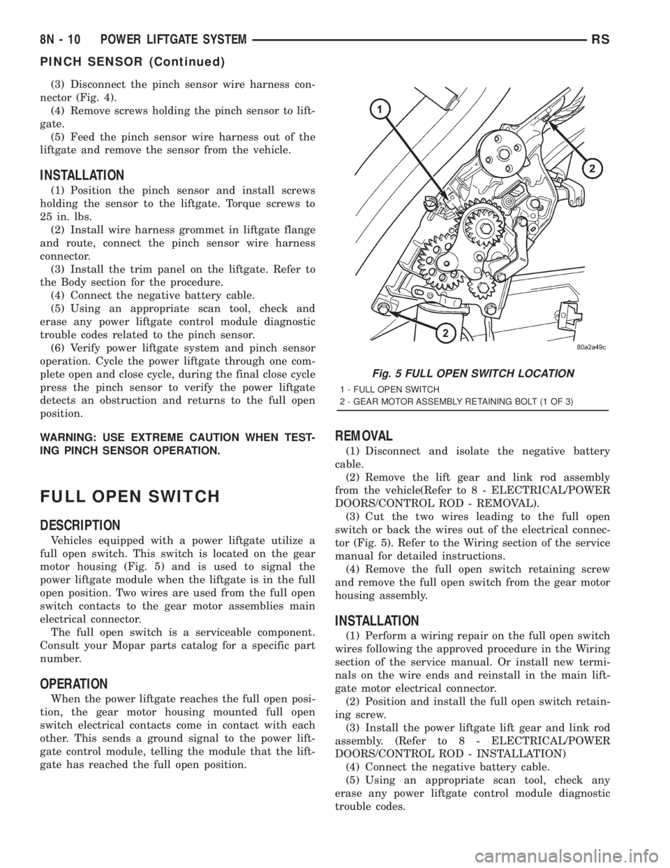
Vehicles equipped with a power liftgate utilize a
full open switch. This switch is located on the gear
motor housing (Fig. 5) and is used to signal the
power liftgate module when the liftgate is in the full
open position. Two wires are used from the full open
switch contacts to the gear motor assemblies main
electrical connector.
The full open switch is a serviceable component.
Consult your Mopar parts catalog for a specific part
number.
OPERATION
When the power liftgate reaches the full open posi-
tion, the gear motor housing mounted full open
switch electrical contacts come in contact with each
other. This sends a ground signal to the power lift-
gate control module, telling the module that the lift-
gate has reached the full open position.
REMOVAL
(1) Disconnect and isolate the negative battery
cable.
(2) Remove the lift gear and link rod assembly
from the vehicle(Refer to 8 - ELECTRICAL/POWER
DOORS/CONTROL ROD - REMOVAL).
(3) Cut the two wires leading to the full open
switch or back the wires out of the electrical connec-
tor (Fig. 5). Refer to the Wiring section of the service
manual for detailed instructions.
(4) Remove the full open switch retaining screw
and remove the full open switch from the gear motor
housing assembly.
INSTALLATION
(1) Perform a wiring repair on the full open switch
wires following the approved procedure in the Wiring
section of the service manual. Or install new termi-
nals on the wire ends and reinstall in the main lift-
gate motor electrical connector.
(2) Position and install the full open switch retain-
ing screw.
(3) Install the power liftgate lift gear and link rod
assembly. (Refer to 8 - ELECTRICAL/POWER
DOORS/CONTROL ROD - INSTALLATION)
(4) Connect the negative battery cable.
(5) Using an appropriate scan tool, check any
erase any power liftgate control module diagnostic
trouble codes.
Fig. 5 FULL OPEN SWITCH LOCATION
1 - FULL OPEN SWITCH
2 - GEAR MOTOR ASSEMBLY RETAINING BOLT (1 OF 3)
8N - 10 POWER LIFTGATE SYSTEMRS
PINCH SENSOR (Continued)
Page 1991 of 4284
(6) Verify power liftgate system and full open
switch operation. Cycle the power liftgate through
one complete open and close cycle, this will allow the
power liftgate control module to relearn its cycle with
the new components.
LIFTGATE MOTOR
DESCRIPTION
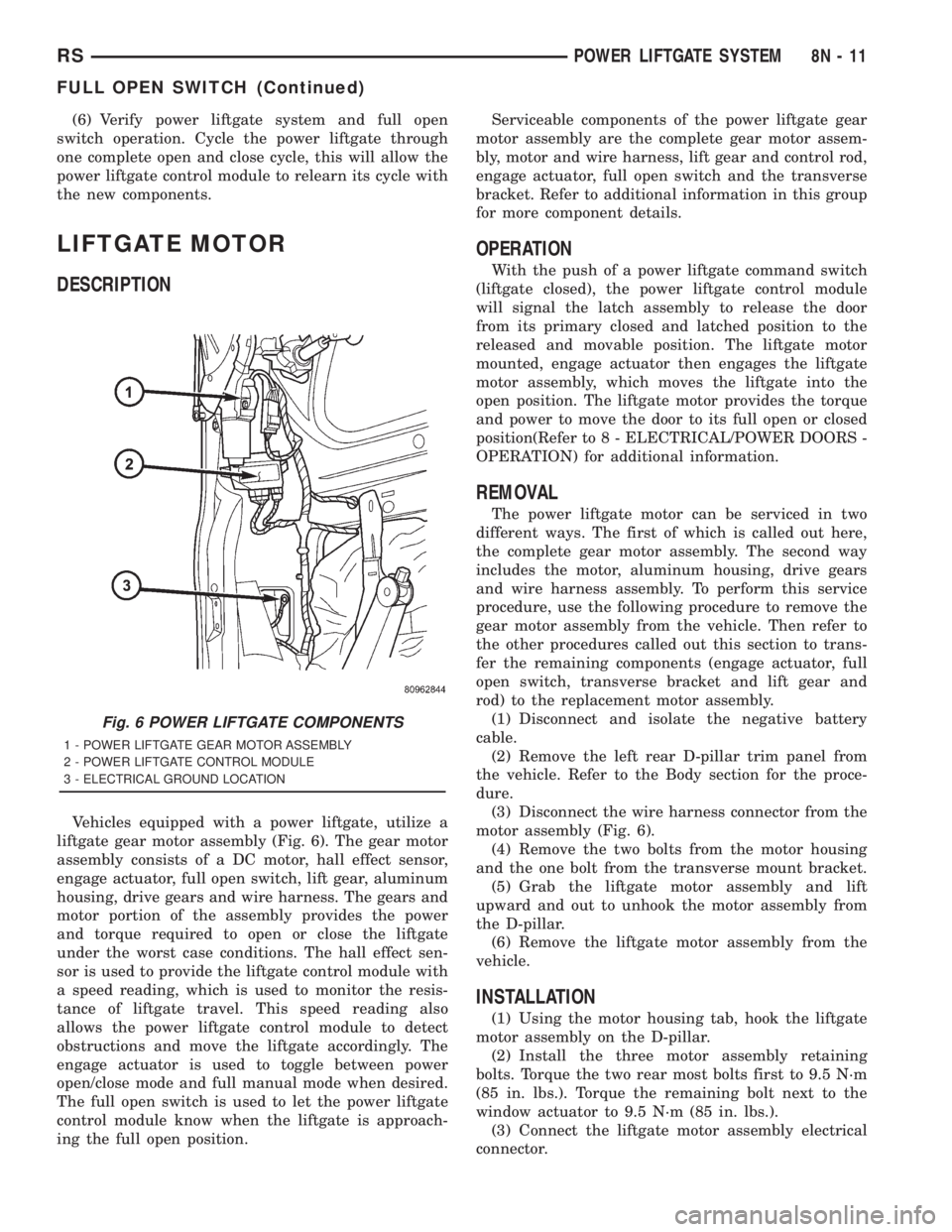
Vehicles equipped with a power liftgate, utilize a
liftgate gear motor assembly (Fig. 6). The gear motor
assembly consists of a DC motor, hall effect sensor,
engage actuator, full open switch, lift gear, aluminum
housing, drive gears and wire harness. The gears and
motor portion of the assembly provides the power
and torque required to open or close the liftgate
under the worst case conditions. The hall effect sen-
sor is used to provide the liftgate control module with
a speed reading, which is used to monitor the resis-
tance of liftgate travel. This speed reading also
allows the power liftgate control module to detect
obstructions and move the liftgate accordingly. The
engage actuator is used to toggle between power
open/close mode and full manual mode when desired.
The full open switch is used to let the power liftgate
control module know when the liftgate is approach-
ing the full open position.Serviceable components of the power liftgate gear
motor assembly are the complete gear motor assem-
bly, motor and wire harness, lift gear and control rod,
engage actuator, full open switch and the transverse
bracket. Refer to additional information in this group
for more component details.
OPERATION
With the push of a power liftgate command switch
(liftgate closed), the power liftgate control module
will signal the latch assembly to release the door
from its primary closed and latched position to the
released and movable position. The liftgate motor
mounted, engage actuator then engages the liftgate
motor assembly, which moves the liftgate into the
open position. The liftgate motor provides the torque
and power to move the door to its full open or closed
position(Refer to 8 - ELECTRICAL/POWER DOORS -
OPERATION) for additional information.
REMOVAL
The power liftgate motor can be serviced in two
different ways. The first of which is called out here,
the complete gear motor assembly. The second way
includes the motor, aluminum housing, drive gears
and wire harness assembly. To perform this service
procedure, use the following procedure to remove the
gear motor assembly from the vehicle. Then refer to
the other procedures called out this section to trans-
fer the remaining components (engage actuator, full
open switch, transverse bracket and lift gear and
rod) to the replacement motor assembly.
(1) Disconnect and isolate the negative battery
cable.
(2) Remove the left rear D-pillar trim panel from
the vehicle. Refer to the Body section for the proce-
dure.
(3) Disconnect the wire harness connector from the
motor assembly (Fig. 6).
(4) Remove the two bolts from the motor housing
and the one bolt from the transverse mount bracket.
(5) Grab the liftgate motor assembly and lift
upward and out to unhook the motor assembly from
the D-pillar.
(6) Remove the liftgate motor assembly from the
vehicle.
INSTALLATION
(1) Using the motor housing tab, hook the liftgate
motor assembly on the D-pillar.
(2) Install the three motor assembly retaining
bolts. Torque the two rear most bolts first to 9.5 N´m
(85 in. lbs.). Torque the remaining bolt next to the
window actuator to 9.5 N´m (85 in. lbs.).
(3) Connect the liftgate motor assembly electrical
connector.
Fig. 6 POWER LIFTGATE COMPONENTS
1 - POWER LIFTGATE GEAR MOTOR ASSEMBLY
2 - POWER LIFTGATE CONTROL MODULE
3 - ELECTRICAL GROUND LOCATION
RSPOWER LIFTGATE SYSTEM8N-11
FULL OPEN SWITCH (Continued)
Page 1993 of 4284
(4) Install the left rear D-pillar trim on the vehi-
cle. Refer to Body for the procedure.
(5) Connect the negative battery cable.
(6) Using an appropriate scan tool, check and
erase any power liftgate control module diagnostic
trouble codes.
(7) Verify power liftgate system and engage actua-
tor operation. Cycle the power liftgate through one
complete open and close cycle.
TRANSVERSE BRACKET
DESCRIPTION
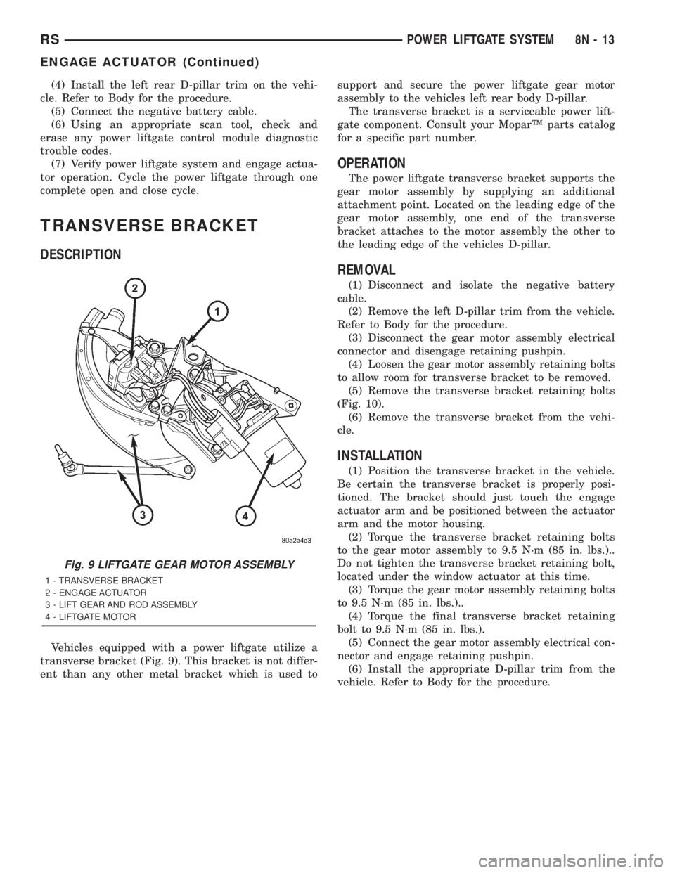
Vehicles equipped with a power liftgate utilize a
transverse bracket (Fig. 9). This bracket is not differ-
ent than any other metal bracket which is used tosupport and secure the power liftgate gear motor
assembly to the vehicles left rear body D-pillar.
The transverse bracket is a serviceable power lift-
gate component. Consult your MoparŸ parts catalog
for a specific part number.
OPERATION
The power liftgate transverse bracket supports the
gear motor assembly by supplying an additional
attachment point. Located on the leading edge of the
gear motor assembly, one end of the transverse
bracket attaches to the motor assembly the other to
the leading edge of the vehicles D-pillar.
REMOVAL
(1) Disconnect and isolate the negative battery
cable.
(2) Remove the left D-pillar trim from the vehicle.
Refer to Body for the procedure.
(3) Disconnect the gear motor assembly electrical
connector and disengage retaining pushpin.
(4) Loosen the gear motor assembly retaining bolts
to allow room for transverse bracket to be removed.
(5) Remove the transverse bracket retaining bolts
(Fig. 10).
(6) Remove the transverse bracket from the vehi-
cle.
INSTALLATION
(1) Position the transverse bracket in the vehicle.
Be certain the transverse bracket is properly posi-
tioned. The bracket should just touch the engage
actuator arm and be positioned between the actuator
arm and the motor housing.
(2) Torque the transverse bracket retaining bolts
to the gear motor assembly to 9.5 N´m (85 in. lbs.)..
Do not tighten the transverse bracket retaining bolt,
located under the window actuator at this time.
(3) Torque the gear motor assembly retaining bolts
to 9.5 N´m (85 in. lbs.)..
(4) Torque the final transverse bracket retaining
bolt to 9.5 N´m (85 in. lbs.).
(5) Connect the gear motor assembly electrical con-
nector and engage retaining pushpin.
(6) Install the appropriate D-pillar trim from the
vehicle. Refer to Body for the procedure.
Fig. 9 LIFTGATE GEAR MOTOR ASSEMBLY
1 - TRANSVERSE BRACKET
2 - ENGAGE ACTUATOR
3 - LIFT GEAR AND ROD ASSEMBLY
4 - LIFTGATE MOTOR
RSPOWER LIFTGATE SYSTEM8N-13
ENGAGE ACTUATOR (Continued)
Page 1994 of 4284
LIFT GEAR & LINK ROD
DESCRIPTION
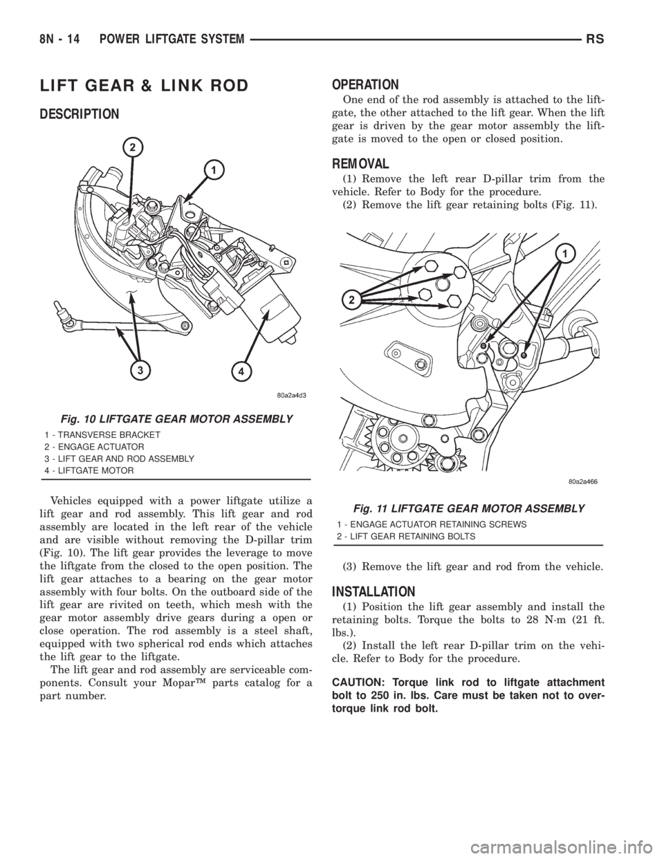
Vehicles equipped with a power liftgate utilize a
lift gear and rod assembly. This lift gear and rod
assembly are located in the left rear of the vehicle
and are visible without removing the D-pillar trim
(Fig. 10). The lift gear provides the leverage to move
the liftgate from the closed to the open position. The
lift gear attaches to a bearing on the gear motor
assembly with four bolts. On the outboard side of the
lift gear are rivited on teeth, which mesh with the
gear motor assembly drive gears during a open or
close operation. The rod assembly is a steel shaft,
equipped with two spherical rod ends which attaches
the lift gear to the liftgate.
The lift gear and rod assembly are serviceable com-
ponents. Consult your MoparŸ parts catalog for a
part number.
OPERATION
One end of the rod assembly is attached to the lift-
gate, the other attached to the lift gear. When the lift
gear is driven by the gear motor assembly the lift-
gate is moved to the open or closed position.
REMOVAL
(1) Remove the left rear D-pillar trim from the
vehicle. Refer to Body for the procedure.
(2) Remove the lift gear retaining bolts (Fig. 11).
(3) Remove the lift gear and rod from the vehicle.
INSTALLATION
(1) Position the lift gear assembly and install the
retaining bolts. Torque the bolts to 28 N´m (21 ft.
lbs.).
(2) Install the left rear D-pillar trim on the vehi-
cle. Refer to Body for the procedure.
CAUTION: Torque link rod to liftgate attachment
bolt to 250 in. lbs. Care must be taken not to over-
torque link rod bolt.
Fig. 10 LIFTGATE GEAR MOTOR ASSEMBLY
1 - TRANSVERSE BRACKET
2 - ENGAGE ACTUATOR
3 - LIFT GEAR AND ROD ASSEMBLY
4 - LIFTGATE MOTOR
Fig. 11 LIFTGATE GEAR MOTOR ASSEMBLY
1 - ENGAGE ACTUATOR RETAINING SCREWS
2 - LIFT GEAR RETAINING BOLTS
8N - 14 POWER LIFTGATE SYSTEMRS
Page 1995 of 4284
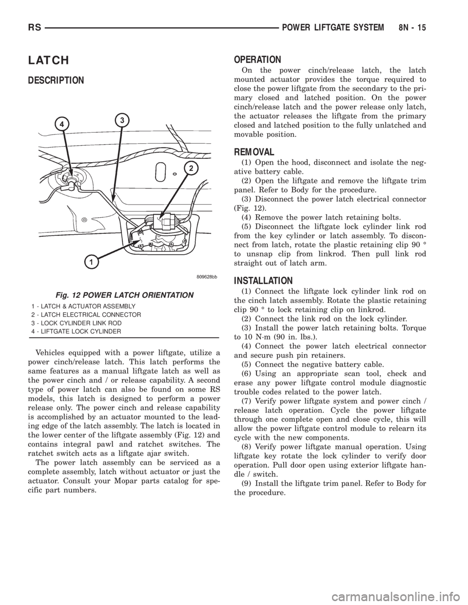
LATCH
DESCRIPTION
Vehicles equipped with a power liftgate, utilize a
power cinch/release latch. This latch performs the
same features as a manual liftgate latch as well as
the power cinch and / or release capability. A second
type of power latch can also be found on some RS
models, this latch is designed to perform a power
release only. The power cinch and release capability
is accomplished by an actuator mounted to the lead-
ing edge of the latch assembly. The latch is located in
the lower center of the liftgate assembly (Fig. 12) and
contains integral pawl and ratchet switches. The
ratchet switch acts as a liftgate ajar switch.
The power latch assembly can be serviced as a
complete assembly, latch without actuator or just the
actuator. Consult your Mopar parts catalog for spe-
cific part numbers.
OPERATION
On the power cinch/release latch, the latch
mounted actuator provides the torque required to
close the power liftgate from the secondary to the pri-
mary closed and latched position. On the power
cinch/release latch and the power release only latch,
the actuator releases the liftgate from the primary
closed and latched position to the fully unlatched and
movable position.
REMOVAL
(1) Open the hood, disconnect and isolate the neg-
ative battery cable.
(2) Open the liftgate and remove the liftgate trim
panel. Refer to Body for the procedure.
(3) Disconnect the power latch electrical connector
(Fig. 12).
(4) Remove the power latch retaining bolts.
(5) Disconnect the liftgate lock cylinder link rod
from the key cylinder or latch assembly. To discon-
nect from latch, rotate the plastic retaining clip 90 É
to unsnap clip from linkrod. Then pull link rod
straight out of latch arm.
INSTALLATION
(1) Connect the liftgate lock cylinder link rod on
the cinch latch assembly. Rotate the plastic retaining
clip 90 É to lock retaining clip on linkrod.
(2) Connect the link rod on the lock cylinder.
(3) Install the power latch retaining bolts. Torque
to 10 N´m (90 in. lbs.).
(4) Connect the power latch electrical connector
and secure push pin retainers.
(5) Connect the negative battery cable.
(6) Using an appropriate scan tool, check and
erase any power liftgate control module diagnostic
trouble codes related to the power latch.
(7) Verify power liftgate system and power cinch /
release latch operation. Cycle the power liftgate
through one complete open and close cycle, this will
allow the power liftgate control module to relearn its
cycle with the new components.
(8) Verify power liftgate manual operation. Using
liftgate key rotate the lock cylinder to verify door
operation. Pull door open using exterior liftgate han-
dle / switch.
(9) Install the liftgate trim panel. Refer to Body for
the procedure.Fig. 12 POWER LATCH ORIENTATION
1 - LATCH & ACTUATOR ASSEMBLY
2 - LATCH ELECTRICAL CONNECTOR
3 - LOCK CYLINDER LINK ROD
4 - LIFTGATE LOCK CYLINDER
RSPOWER LIFTGATE SYSTEM8N-15
Page 1996 of 4284
LATCH ACTUATOR
DESCRIPTION
Vehicles equipped with a power liftgate utilize a
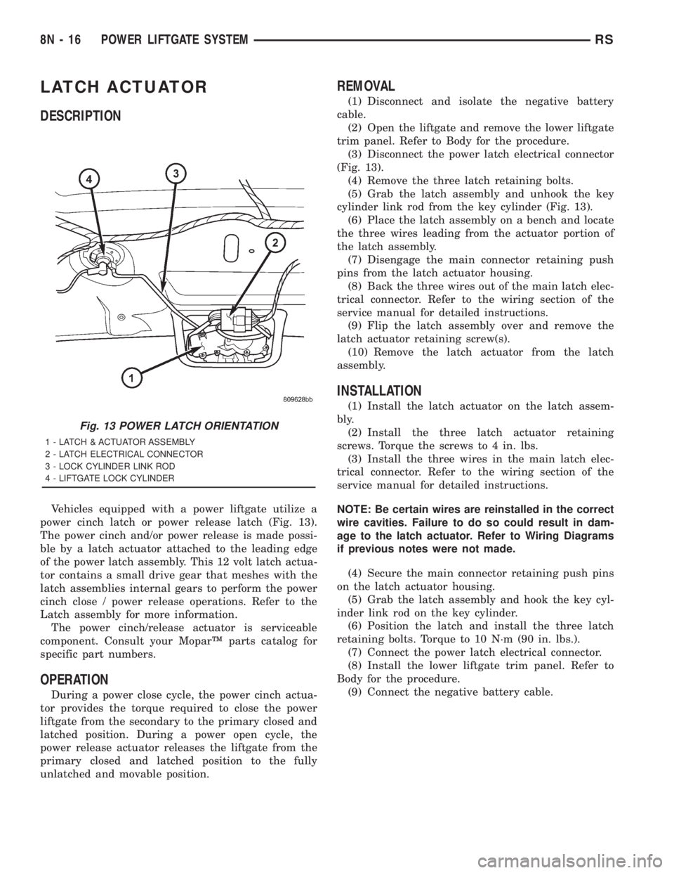
power cinch latch or power release latch (Fig. 13).
The power cinch and/or power release is made possi-
ble by a latch actuator attached to the leading edge
of the power latch assembly. This 12 volt latch actua-
tor contains a small drive gear that meshes with the
latch assemblies internal gears to perform the power
cinch close / power release operations. Refer to the
Latch assembly for more information.
The power cinch/release actuator is serviceable
component. Consult your MoparŸ parts catalog for
specific part numbers.
OPERATION
During a power close cycle, the power cinch actua-
tor provides the torque required to close the power
liftgate from the secondary to the primary closed and
latched position. During a power open cycle, the
power release actuator releases the liftgate from the
primary closed and latched position to the fully
unlatched and movable position.
REMOVAL
(1) Disconnect and isolate the negative battery
cable.
(2) Open the liftgate and remove the lower liftgate
trim panel. Refer to Body for the procedure.
(3) Disconnect the power latch electrical connector
(Fig. 13).
(4) Remove the three latch retaining bolts.
(5) Grab the latch assembly and unhook the key
cylinder link rod from the key cylinder (Fig. 13).
(6) Place the latch assembly on a bench and locate
the three wires leading from the actuator portion of
the latch assembly.
(7) Disengage the main connector retaining push
pins from the latch actuator housing.
(8) Back the three wires out of the main latch elec-
trical connector. Refer to the wiring section of the
service manual for detailed instructions.
(9) Flip the latch assembly over and remove the
latch actuator retaining screw(s).
(10) Remove the latch actuator from the latch
assembly.
INSTALLATION
(1) Install the latch actuator on the latch assem-
bly.
(2) Install the three latch actuator retaining
screws. Torque the screws to 4 in. lbs.
(3) Install the three wires in the main latch elec-
trical connector. Refer to the wiring section of the
service manual for detailed instructions.
NOTE: Be certain wires are reinstalled in the correct
wire cavities. Failure to do so could result in dam-
age to the latch actuator. Refer to Wiring Diagrams
if previous notes were not made.
(4) Secure the main connector retaining push pins
on the latch actuator housing.
(5) Grab the latch assembly and hook the key cyl-
inder link rod on the key cylinder.
(6) Position the latch and install the three latch
retaining bolts. Torque to 10 N´m (90 in. lbs.).
(7) Connect the power latch electrical connector.
(8) Install the lower liftgate trim panel. Refer to
Body for the procedure.
(9) Connect the negative battery cable.
Fig. 13 POWER LATCH ORIENTATION
1 - LATCH & ACTUATOR ASSEMBLY
2 - LATCH ELECTRICAL CONNECTOR
3 - LOCK CYLINDER LINK ROD
4 - LIFTGATE LOCK CYLINDER
8N - 16 POWER LIFTGATE SYSTEMRS
Page 2008 of 4284
STANDARD PROCEDURE - WELLNUT
REPLACEMENT
Vehicles equipped with a power sliding door utilize
wellnuts. These wellnuts are used to hold and isolate
the power sliding door motor to and from the door
inner panel. The wellnut functions like a expandable
rubber core plug, as the screw fastener is threaded
into the wellnut and tightened the wellnuts diameter
increases. This secures the door motor assembly to
the inner panel and keeps the audible motor vibra-
tions to a minimum. If a wellnut shows signs of wear,
it must be replaced. Follow the procedure below if
replacement is necessary.
(1) Remove the door motor from the door inner
panel. (Refer to 8 - ELECTRICAL/POWER DOORS/
MOTOR - REMOVAL) .
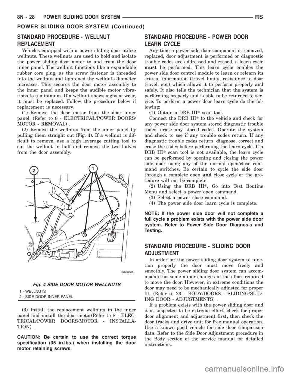
(2) Remove the wellnuts from the inner panel by
pulling them straight out (Fig. 4). If a wellnut is dif-
ficult to remove, use a high leverage cutting tool to
cut the wellnut in half and remove the two halves
from the door assembly.
(3) Install the replacement wellnuts in the inner
panel and install the door motor(Refer to 8 - ELEC-
TRICAL/POWER DOORS/MOTOR - INSTALLA-
TION) .
CAUTION: Be certain to use the correct torque
specification (35 in.lbs.) when installing the door
motor retaining screws.
STANDARD PROCEDURE - POWER DOOR
LEARN CYCLE
Any time a power side door component is removed,
replaced, door adjustment is performed or diagnostic
trouble codes are addressed and erased, a learn cycle
mustbe performed. This learn cycle enables the
power side door control module to learn or relearn its
critical information (travel limits, resistance to door
travel, etc.) which allows it to perform properly and
safely. It also tells the technician that the system is
performing properly and is able to be returned to ser-
vice. To perform a power door learn cycle do the fol-
lowing:
(1) Obtain a DRB IIItscan tool.
Connect the DRB IIItto the vehicle and check for
any power side door system stored diagnostic trouble
codes, erase any stored codes. Operate the system
and check to see if any trouble codes return. If any
diagnostic trouble codes return, diagnose, correct and
erase the codes before performing the learn cycle. If a
DRB IIItscan tool is not available, the learn cycle
can be performed by opening and closing the power
side door using any of the normal open/close com-
mand switches. Be certain to cycle the side door
through a complete openandclose cycle or the pro-
cedure will not be complete.
(2) Using the DRB IIIt, Go into Test Routine
Menu and select a power open command.
(3) Select a power close command.
(4) The power side door learn cycle is complete.
NOTE: If the power side door will not complete a
full cycle a problem exists with the power side door
system. Refer to Power Side Door Diagnosis and
Testing.
STANDARD PROCEDURE - SLIDING DOOR
ADJUSTMENT
In order for the power sliding door system to func-
tion properly the door must move freely and
smoothly. The power sliding door system can accom-
modate for some minor changes in the effort required
to move the door. However, in extreme conditions the
door may need to be mechanically adjusted for proper
fit. (Refer to 23 - BODY/DOORS - SLIDING/SLID-
ING DOOR - ADJUSTMENTS) .
If a problem exists with the power sliding door and
it is suspected to be extreme effort, check for proper
door alignment and adjustment first, then check the
door tracks and drive unit for free manual operation.
Use a known good vehicle for side door comparison
data. Refer to the Side Door Adjustment procedure in
the Body section of the service manual for detailed
instructions.
Fig. 4 SIDE DOOR MOTOR WELLNUTS
1 - WELLNUTS
2 - SIDE DOOR INNER PANEL
8N - 28 POWER SLIDING DOOR SYSTEMRS
POWER SLIDING DOOR SYSTEM (Continued)
Page 2010 of 4284
(8) Disconnect the hold open latch cable from the
latch assembly. Refer to the Body Section of the ser-
vice manual for the procedure.
(9) Disconnect lock actuator link rod from the
latch assembly.
(10) Remove the latch assembly from the vehicle.
INSTALLATION
(1) Position the latch assembly in the vehicle. Be
certain all latch mounted components are installed
on the replacement latch assembly. If not, transfer
components from the old latch to the new latch
assembly.
(2) Connect the lock actuator link rod on the latch
assembly.
(3) Connect the hold open latch cable on the latch
assembly. Refer to the procedure in this section for
detailed instructions.
(4) Connect the inside and outside handle cables
on the latch assembly. Refer to the procedure in the
Body section for detailed instructions.
(5) Connect all electrical connectors leading to the
latch assembly.
(6) With assistance from another person, position
the side door and install the door latch retaining
bolts. Torque to 10 - 12 N´m (100 in. lbs.).
(7) Install the weathershield if necessary. Refer to
the procedure in the Body section for detailed
instructions.
(8) Install the appropriate side door trim panel.
Refer to the procedure in the Body section for
detailed instructions.
(9) Connect the negative battery cable.
SLIDING DOOR MOTOR
DESCRIPTION
Vehicles equipped with a power sliding door utilize
a door motor assembly. The door motor is located in
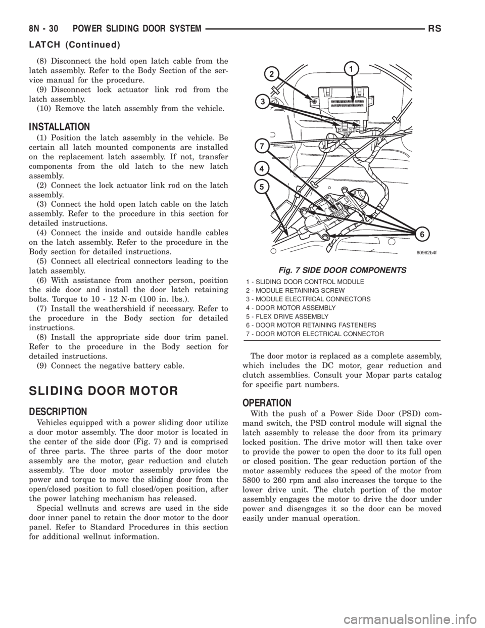
the center of the side door (Fig. 7) and is comprised
of three parts. The three parts of the door motor
assembly are the motor, gear reduction and clutch
assembly. The door motor assembly provides the
power and torque to move the sliding door from the
open/closed position to full closed/open position, after
the power latching mechanism has released.
Special wellnuts and screws are used in the side
door inner panel to retain the door motor to the door
panel. Refer to Standard Procedures in this section
for additional wellnut information.The door motor is replaced as a complete assembly,
which includes the DC motor, gear reduction and
clutch assemblies. Consult your Mopar parts catalog
for specific part numbers.
OPERATION
With the push of a Power Side Door (PSD) com-
mand switch, the PSD control module will signal the
latch assembly to release the door from its primary
locked position. The drive motor will then take over
to provide the power to open the door to its full open
or closed position. The gear reduction portion of the
motor assembly reduces the speed of the motor from
5800 to 260 rpm and also increases the torque to the
lower drive unit. The clutch portion of the motor
assembly engages the motor to drive the door under
power and disengages it so the door can be moved
easily under manual operation.
Fig. 7 SIDE DOOR COMPONENTS
1 - SLIDING DOOR CONTROL MODULE
2 - MODULE RETAINING SCREW
3 - MODULE ELECTRICAL CONNECTORS
4 - DOOR MOTOR ASSEMBLY
5 - FLEX DRIVE ASSEMBLY
6 - DOOR MOTOR RETAINING FASTENERS
7 - DOOR MOTOR ELECTRICAL CONNECTOR
8N - 30 POWER SLIDING DOOR SYSTEMRS
LATCH (Continued)
Page 2011 of 4284
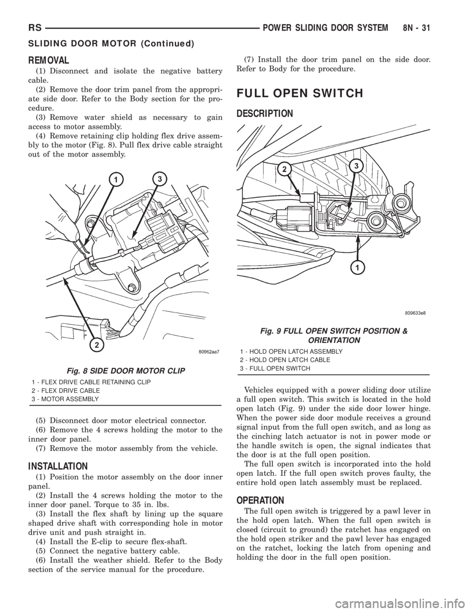
REMOVAL
(1) Disconnect and isolate the negative battery
cable.
(2) Remove the door trim panel from the appropri-
ate side door. Refer to the Body section for the pro-
cedure.
(3) Remove water shield as necessary to gain
access to motor assembly.
(4) Remove retaining clip holding flex drive assem-
bly to the motor (Fig. 8). Pull flex drive cable straight
out of the motor assembly.
(5) Disconnect door motor electrical connector.
(6) Remove the 4 screws holding the motor to the
inner door panel.
(7) Remove the motor assembly from the vehicle.
INSTALLATION
(1) Position the motor assembly on the door inner
panel.
(2) Install the 4 screws holding the motor to the
inner door panel. Torque to 35 in. lbs.
(3) Install the flex shaft by lining up the square
shaped drive shaft with corresponding hole in motor
drive unit and push straight in.
(4) Install the E-clip to secure flex-shaft.
(5) Connect the negative battery cable.
(6) Install the weather shield. Refer to the Body
section of the service manual for the procedure.(7) Install the door trim panel on the side door.
Refer to Body for the procedure.
FULL OPEN SWITCH
DESCRIPTION
Vehicles equipped with a power sliding door utilize
a full open switch. This switch is located in the hold
open latch (Fig. 9) under the side door lower hinge.
When the power side door module receives a ground
signal input from the full open switch, and as long as
the cinching latch actuator is not in power mode or
the handle switch is open, the signal indicates that
the door is at the full open position.
The full open switch is incorporated into the hold
open latch. If the full open switch proves faulty, the
entire hold open latch assembly must be replaced.
OPERATION
The full open switch is triggered by a pawl lever in
the hold open latch. When the full open switch is
closed (circuit to ground) the ratchet has engaged on
the hold open striker and the pawl lever has engaged
on the ratchet, locking the latch from opening and
holding the door in the full open position.
Fig. 8 SIDE DOOR MOTOR CLIP
1 - FLEX DRIVE CABLE RETAINING CLIP
2 - FLEX DRIVE CABLE
3 - MOTOR ASSEMBLY
Fig. 9 FULL OPEN SWITCH POSITION &
ORIENTATION
1 - HOLD OPEN LATCH ASSEMBLY
2 - HOLD OPEN LATCH CABLE
3 - FULL OPEN SWITCH
RSPOWER SLIDING DOOR SYSTEM8N-31
SLIDING DOOR MOTOR (Continued)
Page 2014 of 4284
(4) Disconnect the flex drive assembly from the
lower drive unit. Expand the flex drive collar until
the lower drive unit can be pulled straight off.
(5) Remove the lower drive unit from the vehicle.
INSTALLATION
(1)Position the lower drive unit near the lower hinge.
(2) Connect the flex drive assembly on the lower
drive unit. Push the flex drive collar straight on until
the it snaps in place (Fig. 12).
(3) Install the lower drive unit retaining fasteners
(Fig. 12). Torque the larger allen headed center stud
to 9 N´m (80 in. lbs.). Torque the smaller screw to 3
N´m (28 in. lbs.).
(4) Install the lower drive unit cover and retaining
screws (Fig. 11).
(5) Connect the negative battery cable.
LOWER DRIVE UNIT TRACK &
RACK
DESCRIPTION
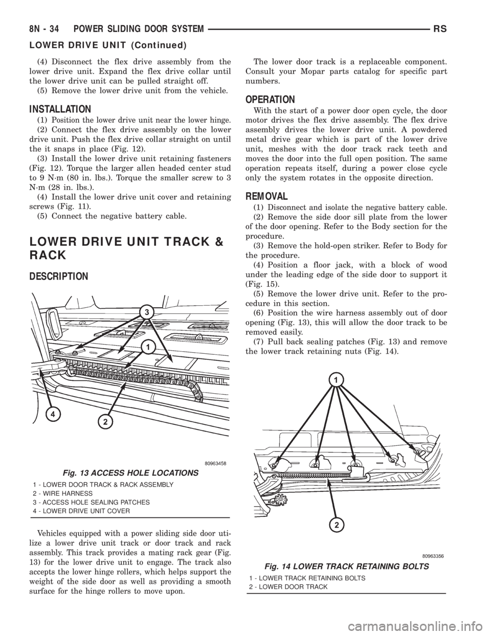
Vehicles equipped with a power sliding side door uti-
lize a lower drive unit track or door track and rack
assembly. This track provides a mating rack gear (Fig.
13) for the lower drive unit to engage. The track also
accepts the lower hinge rollers, which helps support the
weight of the side door as well as providing a smooth
surface for the hinge rollers to move upon.
The lower door track is a replaceable component.
Consult your Mopar parts catalog for specific part
numbers.
OPERATION
With the start of a power door open cycle, the door
motor drives the flex drive assembly. The flex drive
assembly drives the lower drive unit. A powdered
metal drive gear which is part of the lower drive
unit, meshes with the door track rack teeth and
moves the door into the full open position. The same
operation repeats itself, during a power close cycle
only the system rotates in the opposite direction.
REMOVAL
(1)Disconnect and isolate the negative battery cable.
(2) Remove the side door sill plate from the lower
of the door opening. Refer to the Body section for the
procedure.
(3) Remove the hold-open striker. Refer to Body for
the procedure.
(4) Position a floor jack, with a block of wood
under the leading edge of the side door to support it
(Fig. 15).
(5) Remove the lower drive unit. Refer to the pro-
cedure in this section.
(6) Position the wire harness assembly out of door
opening (Fig. 13), this will allow the door track to be
removed easily.
(7) Pull back sealing patches (Fig. 13) and remove
the lower track retaining nuts (Fig. 14).
Fig. 13 ACCESS HOLE LOCATIONS
1 - LOWER DOOR TRACK & RACK ASSEMBLY
2 - WIRE HARNESS
3 - ACCESS HOLE SEALING PATCHES
4 - LOWER DRIVE UNIT COVER
Fig. 14 LOWER TRACK RETAINING BOLTS
1 - LOWER TRACK RETAINING BOLTS
2 - LOWER DOOR TRACK
8N - 34 POWER SLIDING DOOR SYSTEMRS
LOWER DRIVE UNIT (Continued)