torque CHRYSLER VOYAGER 2001 Service Manual
[x] Cancel search | Manufacturer: CHRYSLER, Model Year: 2001, Model line: VOYAGER, Model: CHRYSLER VOYAGER 2001Pages: 4284, PDF Size: 83.53 MB
Page 2015 of 4284
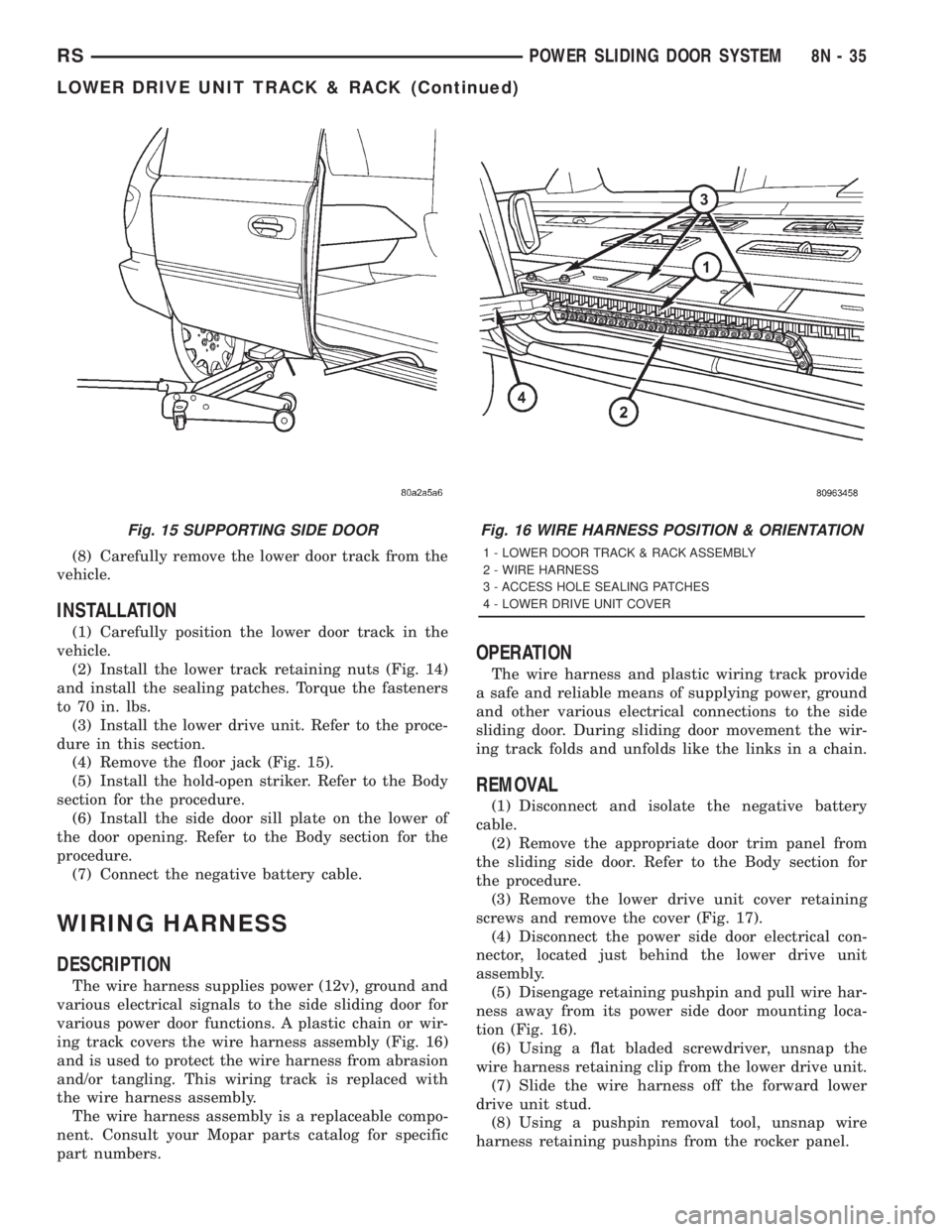
(8) Carefully remove the lower door track from the
vehicle.
INSTALLATION
(1) Carefully position the lower door track in the
vehicle.
(2) Install the lower track retaining nuts (Fig. 14)
and install the sealing patches. Torque the fasteners
to 70 in. lbs.
(3) Install the lower drive unit. Refer to the proce-
dure in this section.
(4) Remove the floor jack (Fig. 15).
(5) Install the hold-open striker. Refer to the Body
section for the procedure.
(6) Install the side door sill plate on the lower of
the door opening. Refer to the Body section for the
procedure.
(7) Connect the negative battery cable.
WIRING HARNESS
DESCRIPTION
The wire harness supplies power (12v), ground and
various electrical signals to the side sliding door for
various power door functions. A plastic chain or wir-
ing track covers the wire harness assembly (Fig. 16)
and is used to protect the wire harness from abrasion
and/or tangling. This wiring track is replaced with
the wire harness assembly.
The wire harness assembly is a replaceable compo-
nent. Consult your Mopar parts catalog for specific
part numbers.
OPERATION
The wire harness and plastic wiring track provide
a safe and reliable means of supplying power, ground
and other various electrical connections to the side
sliding door. During sliding door movement the wir-
ing track folds and unfolds like the links in a chain.
REMOVAL
(1) Disconnect and isolate the negative battery
cable.
(2) Remove the appropriate door trim panel from
the sliding side door. Refer to the Body section for
the procedure.
(3) Remove the lower drive unit cover retaining
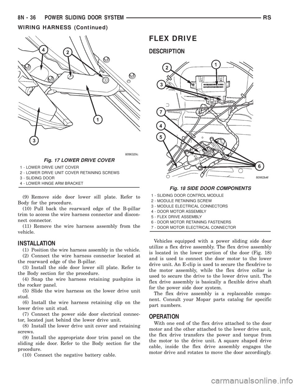
screws and remove the cover (Fig. 17).
(4) Disconnect the power side door electrical con-
nector, located just behind the lower drive unit
assembly.
(5) Disengage retaining pushpin and pull wire har-
ness away from its power side door mounting loca-
tion (Fig. 16).
(6) Using a flat bladed screwdriver, unsnap the
wire harness retaining clip from the lower drive unit.
(7) Slide the wire harness off the forward lower
drive unit stud.
(8) Using a pushpin removal tool, unsnap wire
harness retaining pushpins from the rocker panel.
Fig. 15 SUPPORTING SIDE DOORFig. 16 WIRE HARNESS POSITION & ORIENTATION
1 - LOWER DOOR TRACK & RACK ASSEMBLY
2 - WIRE HARNESS
3 - ACCESS HOLE SEALING PATCHES
4 - LOWER DRIVE UNIT COVER
RSPOWER SLIDING DOOR SYSTEM8N-35
LOWER DRIVE UNIT TRACK & RACK (Continued)
Page 2016 of 4284
(9) Remove side door lower sill plate. Refer to
Body for the procedure.
(10) Pull back the rearward edge of the B-pillar
trim to access the wire harness connector and discon-
nect connector.
(11) Remove the wire harness assembly from the
vehicle.
INSTALLATION
(1)Position the wire harness assembly in the vehicle.
(2) Connect the wire harness connector located at
the rearward edge of the B-pillar.
(3) Install the side door lower sill plate. Refer to
the Body section for the procedure.
(4) Snap the wire harness retaining pushpins in
the rocker panel.
(5) Slide the wire harness on the lower drive unit
stud.
(6) Install the wire harness retaining clip on the
lower drive unit stud.
(7) Connect the power side door electrical connec-
tor, located just behind the lower drive unit.
(8) Install the lower drive unit cover and retaining
screws.
(9) Install the appropriate door trim panel on the
sliding side door. Refer to the Body section for the
procedure.
(10) Connect the negative battery cable.
FLEX DRIVE
DESCRIPTION
Vehicles equipped with a power sliding side door
utilize a flex drive assembly. The flex drive assembly
is located in the lower portion of the door (Fig. 18)
and is used to connect the door motor to the lower
drive unit. An E-clip is used to secure the flexdrive to
the motor assembly, while the flex drive collar is
used to secure the drive to the lower drive unit. The
flex drive assembly is basically a flexible drive shaft
for the power side door system.
The flex drive assembly is a replaceable compo-
nent. Consult your Mopar parts catalog for specific
part numbers.
OPERATION
With one end of the flex drive attached to the door
motor and the other attached to the lower drive unit,
the flex drive transfers the power and torque from
the motor to the drive unit. A square shaped drive
cable, inside the flex drive assembly engages the
motor drive and rotates to move the door accordingly.
Fig. 17 LOWER DRIVE COVER
1 - LOWER DRIVE UNIT COVER
2 - LOWER DRIVE UNIT COVER RETAINING SCREWS
3 - SLIDING DOOR
4 - LOWER HINGE ARM BRACKET
Fig. 18 SIDE DOOR COMPONENTS
1 - SLIDING DOOR CONTROL MODULE
2 - MODULE RETAINING SCREW
3 - MODULE ELECTRICAL CONNECTORS
4 - DOOR MOTOR ASSEMBLY
5 - FLEX DRIVE ASSEMBLY
6 - DOOR MOTOR RETAINING FASTENERS
7 - DOOR MOTOR ELECTRICAL CONNECTOR
8N - 36 POWER SLIDING DOOR SYSTEMRS
WIRING HARNESS (Continued)
Page 2039 of 4284
fails to operate in more than one direction, perform
the following tests. For complete circuit diagrams,
refer toPower Seatin Wiring Diagrams.
(1) Check the power seat circuit breaker under the
seat. If OK, go to Step 2. If not OK, replace the
faulty power seat circuit breaker.
(2) Check for battery voltage at the power seat cir-
cuit breaker under the seat. If OK, go to Step 3. If
not OK, repair the open fused B(+) circuit to the fuse
in the Intelligent Power Module as required.
(3) Remove the outboard seat cushion side shield
from the seat. Disconnect the seat wire harness con-
nector from the power seat switch connector recepta-
cle. Check for battery voltage at the fused B(+)
circuit cavity of the power seat wire harness connec-
tor for the power seat switch. If OK, go to Step 4. If
not OK, repair the open fused B(+) circuit to the
power seat circuit breaker under the seat as
required.
(4) Check for continuity between the ground cir-
cuit cavity of the power seat wire harness connector
for the power seat switch and a good ground. There
should be continuity. If OK, go to Step 5. If not OK,
repair the open ground circuit to ground as required.
(5) Test the power seat switch. Refer toPower
Seat Switchin the Diagnosis and Testing section of
this group. If the switch tests OK, test the circuits of
the power seat wire harness between the inoperative
power seat track adjuster motor and the power seat
switch for shorts or opens. If the circuits check OK,
replace the faulty power seat track unit. If the cir-
cuits are not OK, repair the power seat wire harness
as required.
REMOVAL
WARNING: SOME VEHICLES ARE EQUIPPED WITH
SEATBACK MOUNTED AIRBAGS. BEFORE
ATTEMPTING TO DIAGNOSE OR SERVICE ANY
SEAT OR POWER SEAT SYSTEM COMPONENT
YOU MUST FIRST DISCONNECT AND ISOLATE THE
BATTERY NEGATIVE CABLE. THEN WAIT TWO MIN-
UTES FOR THE SYSTEM CAPACITOR TO DIS-
CHARGE BEFORE FURTHER SYSTEM SERVICE.
THIS IS THE ONLY SURE WAY TO DISABLE THE
AIRBAG SYSTEM. FAILURE TO DO SO COULD
RESULT IN ACCIDENTAL AIRBAG DEPLOYMENT
AND POSSIBLE PERSONAL INJURY.(1) Remove the appropriate seat from the vehicle.
Refer to Body for the procedure.
(2) Remove two seat back mounting bolts and also
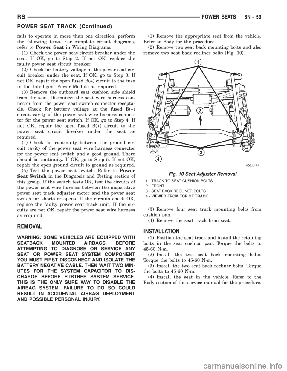
remove two seat back recliner bolts (Fig. 10).
(3) Remove four seat track mounting bolts from
cushion pan.
(4) Remove the seat track from seat.
INSTALLATION
(1) Position the seat track and install the retaining
bolts in the seat cushion pan. Torque the bolts to
45-60 N´m.
(2) Install the two seat back mounting bolts.
Torque the bolts to 45-60 N´m.
(3) Install the two seat back recliner bolts. Torque
the bolts to 45-60 N´m.
(4) Install the seat in the vehicle. Refer to the
Body section of the service manual for the procedure.
Fig. 10 Seat Adjuster Removal
1 - TRACK TO SEAT CUSHION BOLTS
2 - FRONT
3 - SEAT BACK RECLINER BOLTS
4-VIEWED FROM TOP OF TRACK
RSPOWER SEATS8N-59
POWER SEAT TRACK (Continued)
Page 2052 of 4284

CAUTION: Use correct screws when installing the
ORC.
(1) Install the ORC assembly into vehicle.
(2) Connect the wire connector to the ORC.
(3) Install three bolts holding ORC to floor
bracket. Torque bolts to 7.3 - 9.6 N´m (65 to 85 in.
lbs.)
(4) Install the storage bin onto the instrument
panel. Refer to Body, Instrument Panel, Storage Bin,
Installation.
WARNING: DO NOT CONNECT THE BATTERY NEG-
ATIVE CABLE. REFER TO ELECTRICAL,
RESTRAINTS, DIAGNOSIS AND TESTING - AIRBAG
SYSTEM FIRST.
PASSENGER AIRBAG
DESCRIPTION
WARNING: NEVER DISASSEMBLE THE PASSEN-
GER AIRBAG, THE PASSENGER AIRBAG HAS NO
SERVICEABLE PARTS.
The Passenger Airbag is located beneath the
instrument panel and pad assembly. The airbag is
mounted to the back side of the instrument panel
reinforcement.
The instrument panel top pad is the most visible
part of the passenger airbag system. Located under
the instrument panel top pad are the airbag door, the
passenger airbag cushion and the airbag cushion
supporting components.
The passenger airbag includes a magnesium hous-
ing within which the cushion and inflator are
mounted and sealed.
Following a passenger airbag deployment, the pas-
senger airbag and the instrument panel must be
replaced. The passenger airbag cannot be repaired,
and must be replaced if deployed or damaged in any
way.
OPERATION
The passenger airbag is equipped with two infla-
tors, each with three levels of pressure output. The
inflators seal the hole in the airbag cushion so it can
discharge the gas it produces directly into the cush-
ion when supplied with the proper electrical signal.
Following an airbag deployment, the airbag cushion
quickly deflates by venting this gas through the
cushion material towards the instrument panel.
The passenger airbag is secured with screws to the
instrument panel beneath the instrument panel top
pad and above the glove box opening. The instrumentpanel top pad above the glove box opening conceals
the airbag door and a predetermined hinge line
beneath its decorative cover. Upon airbag deploy-
ment, the top pad will bend at the hinge line and the
door will fold back out of the way onto the top of the
instrument panel.
WHEN THE FRONT AIRBAG SYSTEM IS
DEPLOYED BECAUSE OF A COLLISION, THE
FOLLOWING MUST BE REPLACED:
²COMPLETE STEERING COLUMN ASSEMBLY
²LOWER STEERING COUPLER
²STEERING WHEEL
²STEERING COLUMN CLOCK SPRING
²DRIVER AIRBAG COVER/HORN SWITCH
²DRIVER AIRBAG
²PASSENGER AIRBAG
²UPPER INSTRUMENT PANEL WITH PAD
CARE OF UNDEPLOYED AIRBAGS
Airbags must be stored in their original special
container until used for service. At no time should a
source of electricity be permitted near the inflator on
the back of an airbag. When carrying or handling an
undeployed airbag, the trim side of the airbag should
be pointing away from the body to minimize possibil-
ity of injury if accidental deployment occurs. Do not
place undeployed airbag face down on a solid surface,
the airbag will propel into the air if accidental
deployment occurs.
STANDARD PROCEDURE - DEPLOYED
PASSENGER AIRBAG CLEAN UP
Roll or fold the passenger airbag towards the
instrument panel surface and close the door over the
folded bag. Then tape the door shut.
Use a vacuum cleaner to remove any residual pow-
der from the vehicle interior. Work from the outside
in to avoid kneeling or sitting in a contaminated
area. Vacuum the heater and A/C outlets as well. If
HVAC was in RECIRC mode at time of airbag
deployment, operate HVAC blower on low speed/heat
and vacuum powder residue expelled from the heat
outlets. Multiple vacuum cleaning may be necessary
to decontaminate the interior of the vehicle.
SERVICE OF DEPLOYED AIRBAG
If a Passenger Airbag has been deployed, but not
due to a collision, replace the following:
²Passenger Airbag
²Upper instrument panel with pad
The component above must be replaced because
they cannot be reused. Inspect the heat duct near the
passenger airbag for any damage replace as neces-
sary. Replace any other passenger airbag system
components if damaged.
8O - 6 RESTRAINTSRS
OCCUPANT RESTRAINT CONTROLLER (Continued)
Page 2054 of 4284

(2) Remove cover from seat belt turning loop.
(3) Remove bolt attaching turning loop to shoulder
belt height adjuster (Fig. 2).
(4) Remove turning loop from B-pillar.
(5) Remove lower B-pillar trim cover or quarter
trim panel.
(6) Remove bolt attaching seat belt retractor to
B-pillar (Fig. 2).
(7) Lift retractor upward and disengage arrow
head retainer attaching retractor to B-pillar.
(8) Remove seat belt from vehicle.
INSTALLATION
Inspect the condition of the shoulder belt and lap
belt. Replace any belt that is cut, frayed, torn, or
damaged in any way. Also, replace the shoulder belt
if the retractor is either damaged or inoperative.
(1) Place seat belt into position.
(2) Lower retractor into position B-pillar.
(3) Install bolt attaching seat belt retractor to
B-pillar. Tighten all seat belt anchor bolts to 39 N´m
(29 ft. lbs.) torque.
(4) Install turning loop onto B-pillar.
(5) Install lower B-pillar trim cover or quarter
trim panel.
(6) Install bolt attaching turning loop to shoulder
belt height adjuster. Tighten all seat belt anchor
bolts to 39 N´m (29 ft. lbs.) torque.
(7) Press cover onto the seat belt turning loop.(8) Install shoulder harness height adjuster knob
by pushing onto the adjuster.
SEAT BELT FIRST ROW
ANCHOR BRACKET - LWB
REMOVAL
(1) Remove lower quarter trim panel.
(2) Remove bolt attaching first row seat belt
anchor bracket to floor.
(3) Remove bracket from vehicle.
INSTALLATION
(1) Position bracket to vehicle.
(2) Install bolt attaching first row seat belt anchor
bracket to floor.
(3) Install lower quarter trim panel.
NOTE: The tightening specification for all seat belt
anchor bolts is 39 N´m (29 ft. lbs.) torque.
SEAT BELT LEFT FIRST ROW
OUTBOARD - SWB THREE
DOOR
REMOVAL
(1) Remove first and second row seats. Refer to
Owner's manual for proper procedures.
(2) Remove shoulder harness height adjuster knob
by pulling it straight away from adjuster.
(3) Slide floor anchor cover from over the anchor
bolt.
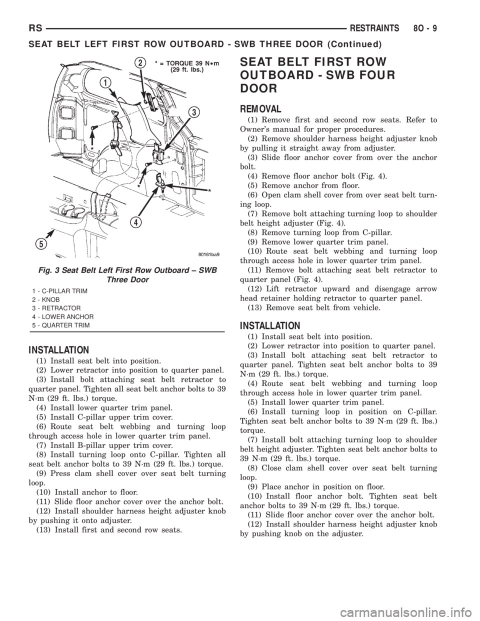
(4) Remove floor anchor bolt (Fig. 3).
(5) Remove anchor from floor.
(6) Open clam shell cover from over seat belt turn-
ing loop.
(7) Remove bolt attaching turning loop to shoulder
belt height adjuster.
(8) Remove turning loop from C-pillar.
(9) Remove B-pillar upper trim cover.
(10) Remove C-pillar upper trim cover.
(11) Remove lower quarter trim panel.
(12) Route seat belt webbing and turning loop
through access hole in lower quarter trim panel.
(13) Remove bolt attaching seat belt retractor to
quarter panel.
(14) Lift retractor upward and disengage arrow
head retainer attaching retractor to quarter panel
(Fig. 3).
(15) Remove seat belt from vehicle.
Fig. 2 SEAT BELT - OUTBOARD FRONT
1 - B-PILLAR TRIM LOWER
2 - BELT
3 - B-PILLAR TRIM UPPER
4 - HEIGHT ADJUSTER
5 - KNOB
6 - B-PILLAR TRIM LOWER
7 - FLOOR ANCHOR
8 - FLOOR ANCHOR
9 - 30É OUTBOARD
10 - RETRACTOR
8O - 8 RESTRAINTSRS
SEAT BELT OUTBOARD FRONT (Continued)
Page 2055 of 4284
INSTALLATION
(1) Install seat belt into position.
(2) Lower retractor into position to quarter panel.
(3) Install bolt attaching seat belt retractor to
quarter panel. Tighten all seat belt anchor bolts to 39
N´m (29 ft. lbs.) torque.
(4) Install lower quarter trim panel.
(5) Install C-pillar upper trim cover.
(6) Route seat belt webbing and turning loop
through access hole in lower quarter trim panel.
(7) Install B-pillar upper trim cover.
(8) Install turning loop onto C-pillar. Tighten all
seat belt anchor bolts to 39 N´m (29 ft. lbs.) torque.
(9) Press clam shell cover over seat belt turning
loop.
(10) Install anchor to floor.
(11) Slide floor anchor cover over the anchor bolt.
(12) Install shoulder harness height adjuster knob
by pushing it onto adjuster.
(13) Install first and second row seats.
SEAT BELT FIRST ROW
OUTBOARD - SWB FOUR
DOOR
REMOVAL
(1) Remove first and second row seats. Refer to
Owner's manual for proper procedures.
(2) Remove shoulder harness height adjuster knob
by pulling it straight away from adjuster.
(3) Slide floor anchor cover from over the anchor
bolt.
(4) Remove floor anchor bolt (Fig. 4).
(5) Remove anchor from floor.
(6) Open clam shell cover from over seat belt turn-
ing loop.
(7) Remove bolt attaching turning loop to shoulder
belt height adjuster (Fig. 4).
(8) Remove turning loop from C-pillar.
(9) Remove lower quarter trim panel.
(10) Route seat belt webbing and turning loop
through access hole in lower quarter trim panel.
(11) Remove bolt attaching seat belt retractor to
quarter panel (Fig. 4).
(12) Lift retractor upward and disengage arrow
head retainer holding retractor to quarter panel.
(13) Remove seat belt from vehicle.
INSTALLATION
(1) Install seat belt into position.
(2) Lower retractor into position to quarter panel.
(3) Install bolt attaching seat belt retractor to
quarter panel. Tighten seat belt anchor bolts to 39
N´m (29 ft. lbs.) torque.
(4) Route seat belt webbing and turning loop
through access hole in lower quarter trim panel.
(5) Install lower quarter trim panel.
(6) Install turning loop in position on C-pillar.
Tighten seat belt anchor bolts to 39 N´m (29 ft. lbs.)
torque.
(7) Install bolt attaching turning loop to shoulder
belt height adjuster. Tighten seat belt anchor bolts to
39 N´m (29 ft. lbs.) torque.
(8) Close clam shell cover over seat belt turning
loop.
(9) Place anchor in position on floor.
(10) Install floor anchor bolt. Tighten seat belt
anchor bolts to 39 N´m (29 ft. lbs.) torque.
(11) Slide floor anchor cover over the anchor bolt.
(12) Install shoulder harness height adjuster knob
by pushing knob on the adjuster.
Fig. 3 Seat Belt Left First Row Outboard ± SWB
Three Door
1 - C-PILLAR TRIM
2 - KNOB
3 - RETRACTOR
4 - LOWER ANCHOR
5 - QUARTER TRIM
RSRESTRAINTS8O-9
SEAT BELT LEFT FIRST ROW OUTBOARD - SWB THREE DOOR (Continued)
Page 2056 of 4284
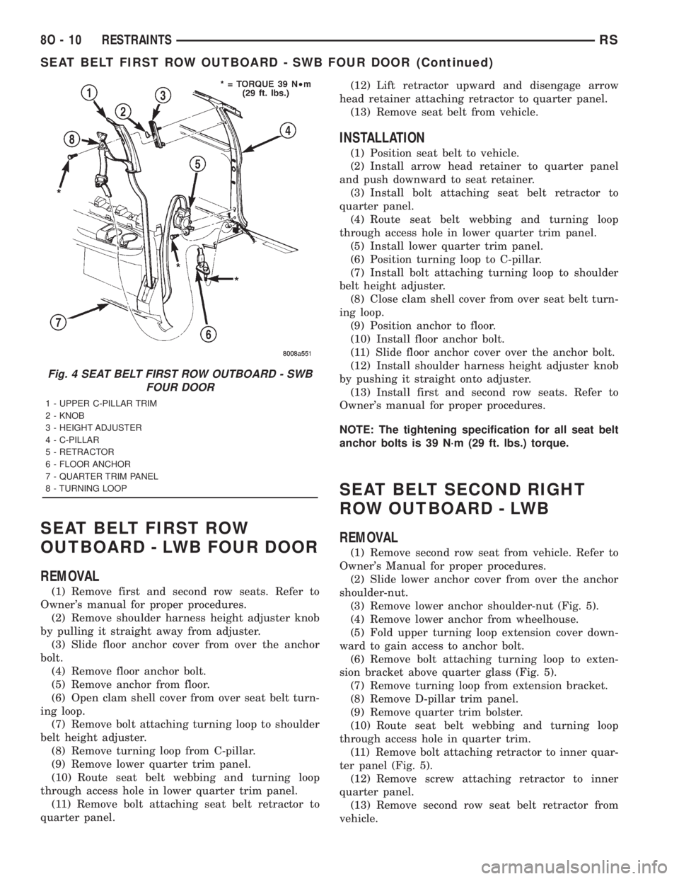
SEAT BELT FIRST ROW
OUTBOARD - LWB FOUR DOOR
REMOVAL
(1) Remove first and second row seats. Refer to
Owner's manual for proper procedures.
(2) Remove shoulder harness height adjuster knob
by pulling it straight away from adjuster.
(3) Slide floor anchor cover from over the anchor
bolt.
(4) Remove floor anchor bolt.
(5) Remove anchor from floor.
(6) Open clam shell cover from over seat belt turn-
ing loop.
(7) Remove bolt attaching turning loop to shoulder
belt height adjuster.
(8) Remove turning loop from C-pillar.
(9) Remove lower quarter trim panel.
(10) Route seat belt webbing and turning loop
through access hole in lower quarter trim panel.
(11) Remove bolt attaching seat belt retractor to
quarter panel.(12) Lift retractor upward and disengage arrow
head retainer attaching retractor to quarter panel.
(13) Remove seat belt from vehicle.
INSTALLATION
(1) Position seat belt to vehicle.
(2) Install arrow head retainer to quarter panel
and push downward to seat retainer.
(3) Install bolt attaching seat belt retractor to
quarter panel.
(4) Route seat belt webbing and turning loop
through access hole in lower quarter trim panel.
(5) Install lower quarter trim panel.
(6) Position turning loop to C-pillar.
(7) Install bolt attaching turning loop to shoulder
belt height adjuster.
(8) Close clam shell cover from over seat belt turn-
ing loop.
(9) Position anchor to floor.
(10) Install floor anchor bolt.
(11) Slide floor anchor cover over the anchor bolt.
(12) Install shoulder harness height adjuster knob
by pushing it straight onto adjuster.
(13) Install first and second row seats. Refer to
Owner's manual for proper procedures.
NOTE: The tightening specification for all seat belt
anchor bolts is 39 N´m (29 ft. lbs.) torque.
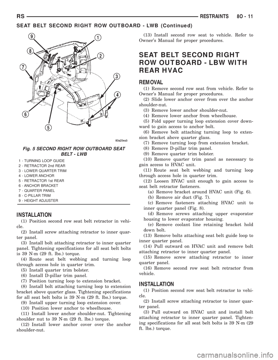
SEAT BELT SECOND RIGHT
ROW OUTBOARD - LWB
REMOVAL
(1) Remove second row seat from vehicle. Refer to
Owner's Manual for proper procedures.
(2) Slide lower anchor cover from over the anchor
shoulder-nut.
(3) Remove lower anchor shoulder-nut (Fig. 5).
(4) Remove lower anchor from wheelhouse.
(5) Fold upper turning loop extension cover down-
ward to gain access to anchor bolt.
(6) Remove bolt attaching turning loop to exten-
sion bracket above quarter glass (Fig. 5).
(7) Remove turning loop from extension bracket.
(8) Remove D-pillar trim panel.
(9) Remove quarter trim bolster.
(10) Route seat belt webbing and turning loop
through access hole in quarter trim.
(11) Remove bolt attaching retractor to inner quar-
ter panel (Fig. 5).
(12) Remove screw attaching retractor to inner
quarter panel.
(13) Remove second row seat belt retractor from
vehicle.
Fig. 4 SEAT BELT FIRST ROW OUTBOARD - SWB
FOUR DOOR
1 - UPPER C-PILLAR TRIM
2 - KNOB
3 - HEIGHT ADJUSTER
4 - C-PILLAR
5 - RETRACTOR
6 - FLOOR ANCHOR
7 - QUARTER TRIM PANEL
8 - TURNING LOOP
8O - 10 RESTRAINTSRS
SEAT BELT FIRST ROW OUTBOARD - SWB FOUR DOOR (Continued)
Page 2057 of 4284
INSTALLATION
(1) Position second row seat belt retractor in vehi-
cle.
(2) Install screw attaching retractor to inner quar-
ter panel.
(3) Install bolt attaching retractor to inner quarter
panel. Tightening specifications for all seat belt bolts
is 39 N´m (29 ft. lbs.) torque.
(4) Route seat belt webbing and turning loop
through access hole in quarter trim.
(5) Install quarter trim bolster.
(6) Install D-pillar trim panel.
(7) Position turning loop to extension bracket.
(8) Install bolt attaching turning loop to extension
bracket above quarter glass. Tightening specifications
for all seat belt bolts is 39 N´m (29 ft. lbs.) torque.
(9) Install upper turning loop extension cover.
(10) Position lower anchor to wheelhouse.
(11) Install lower anchor shoulder-nut. Tightening
shoulder nut to 39 N´m (29 ft. lbs.) torque.
(12) Install lower anchor cover over the anchor
shoulder-nut.(13) Install second row seat to vehicle. Refer to
Owner's Manual for proper procedures.
SEAT BELT SECOND RIGHT
ROW OUTBOARD - LBW WITH
REAR HVAC
REMOVAL
(1) Remove second row seat from vehicle. Refer to
Owner's Manual for proper procedures.
(2) Slide lower anchor cover from over the anchor
shoulder-nut.
(3) Remove lower anchor shoulder-nut.
(4) Remove lower anchor from wheelhouse.
(5) Fold upper turning loop extension cover down-
ward to gain access to anchor bolt.
(6) Remove bolt attaching turning loop to exten-
sion bracket above quarter glass.
(7) Remove turning loop from extension bracket.
(8) Remove D-pillar trim panel.
(9) Remove quarter trim bolster.
(10) Remove quarter trim panel as necessary to
gain access to HVAC unit.
(11) Route seat belt webbing and turning loop
through access hole in quarter trim.
(12) Loosen HVAC unit enough to gain access to
seat belt retractor fasteners.
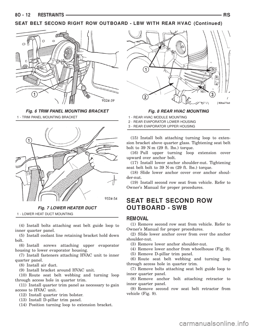
(a) Remove bracket around HVAC unit (Fig. 6).
(b) Remove air duct (Fig. 7).
(c) Remove fasteners attaching HVAC unit to
inner quarter panel (Fig. 8).
(d) Remove screws attaching upper evaporator
housing to lower evaporator housing.
(e) Remove coolant line retaining bracket hold
down bolt.
(13) Remove bolts attaching seat belt guide loop to
inner quarter panel.
(14) Pull outward on HVAC unit and remove bolt
attaching retractor to inner quarter panel.
(15) Remove screw attaching retractor to inner
quarter panel.
(16) Remove second row seat belt retractor from
vehicle.
INSTALLATION
(1) Position second row seat belt retractor to vehi-
cle.
(2) Install screw attaching retractor to inner quar-
ter panel.
(3) Pull outward on HVAC unit and install bolt
attaching retractor to inner quarter panel. Tighten-
ing specifications for all seat belt bolts is 39 N´m (29
ft. lbs.) torque.
Fig. 5 SECOND RIGHT ROW OUTBOARD SEAT
BELT - LWB
1 - TURNING LOOP GUIDE
2 - RETRACTOR 2nd REAR
3 - LOWER QUARTER TRIM
4 - LOWER ANCHOR
5 - RETRACTOR 1st REAR
6 - ANCHOR BRACKET
7 - QUARTER PANEL
8 - C-PILLAR TRIM
9 - HEIGHT ADJUSTER
RSRESTRAINTS8O-11
SEAT BELT SECOND RIGHT ROW OUTBOARD - LWB (Continued)
Page 2058 of 4284
(4) Install bolts attaching seat belt guide loop to
inner quarter panel.
(5) Install coolant line retaining bracket hold down
bolt.
(6) Install screws attaching upper evaporator
housing to lower evaporator housing.
(7) Install fasteners attaching HVAC unit to inner
quarter panel.
(8) Install air duct.
(9) Install bracket around HVAC unit.
(10) Route seat belt webbing and turning loop
through access hole in quarter trim.
(11) Install quarter trim panel as necessary to gain
access to HVAC unit.
(12) Install quarter trim bolster.
(13) Install D-pillar trim panel.
(14) Position turning loop to extension bracket.(15) Install bolt attaching turning loop to exten-
sion bracket above quarter glass. Tightening seat belt
bolt to 39 N´m (29 ft. lbs.) torque.
(16) Pull upper turning loop extension cover
upward over anchor bolt.
(17) Install lower anchor shoulder-nut. Tightening
seat belt bolt to 39 N´m (29 ft. lbs.) torque.
(18) Slide lower anchor cover over anchor shoul-
der-nut.
(19) Install second row seat from vehicle. Refer to
Owner's Manual for proper procedures.
SEAT BELT SECOND ROW
OUTBOARD - SWB
REMOVAL
(1) Remove second row seat from vehicle. Refer to
Owner's Manual for proper procedures.
(2) Slide lower anchor cover from over the anchor
shoulder-nut.
(3) Remove lower anchor shoulder-nut.
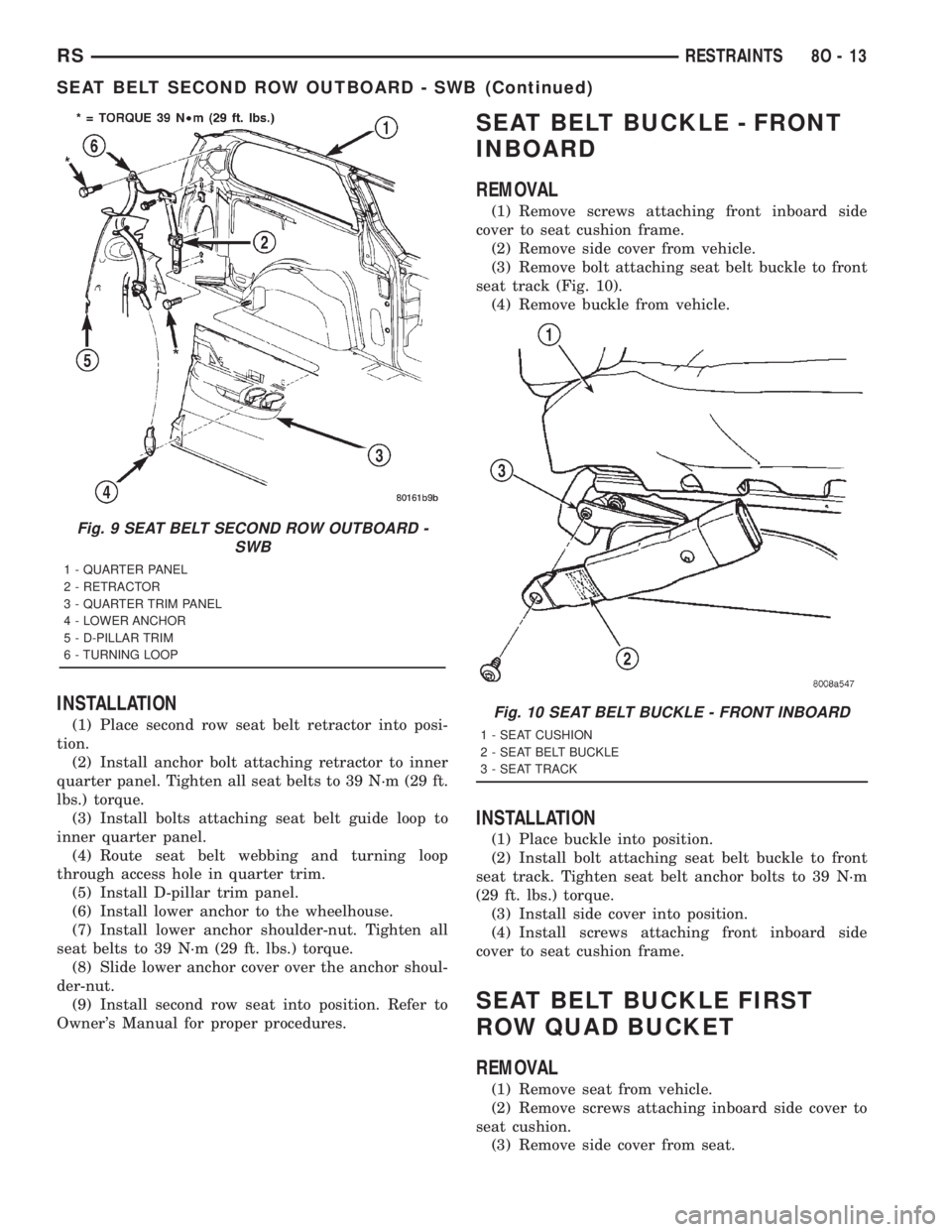
(4) Remove lower anchor from wheelhouse (Fig. 9).
(5) Remove D-pillar trim panel.
(6) Route seat belt webbing and turning loop
through access hole in quarter trim.
(7) Remove bolts attaching seat belt guide loop to
inner quarter panel.
(8) Remove anchor bolt attaching retractor to
inner quarter panel.
(9) Remove second row seat belt retractor from
vehicle (Fig. 9).
Fig. 6 TRIM PANEL MOUNTING BRACKET
1 - TRIM PANEL MOUNTING BRACKET
Fig. 7 LOWER HEATER DUCT
1 - LOWER HEAT DUCT MOUNTING
Fig. 8 REAR HVAC MOUNTING
1 - REAR HVAC MODULE MOUNTING
2 - REAR EVAPORATOR LOWER HOUSING
3 - REAR EVAPORATOR UPPER HOUSING
8O - 12 RESTRAINTSRS
SEAT BELT SECOND RIGHT ROW OUTBOARD - LBW WITH REAR HVAC (Continued)
Page 2059 of 4284
INSTALLATION
(1) Place second row seat belt retractor into posi-
tion.
(2) Install anchor bolt attaching retractor to inner
quarter panel. Tighten all seat belts to 39 N´m (29 ft.
lbs.) torque.
(3) Install bolts attaching seat belt guide loop to
inner quarter panel.
(4) Route seat belt webbing and turning loop
through access hole in quarter trim.
(5) Install D-pillar trim panel.
(6) Install lower anchor to the wheelhouse.
(7) Install lower anchor shoulder-nut. Tighten all
seat belts to 39 N´m (29 ft. lbs.) torque.
(8) Slide lower anchor cover over the anchor shoul-
der-nut.
(9) Install second row seat into position. Refer to
Owner's Manual for proper procedures.
SEAT BELT BUCKLE - FRONT
INBOARD
REMOVAL
(1) Remove screws attaching front inboard side
cover to seat cushion frame.
(2) Remove side cover from vehicle.
(3) Remove bolt attaching seat belt buckle to front
seat track (Fig. 10).
(4) Remove buckle from vehicle.
INSTALLATION
(1) Place buckle into position.
(2) Install bolt attaching seat belt buckle to front
seat track. Tighten seat belt anchor bolts to 39 N´m
(29 ft. lbs.) torque.
(3) Install side cover into position.
(4) Install screws attaching front inboard side
cover to seat cushion frame.
SEAT BELT BUCKLE FIRST
ROW QUAD BUCKET
REMOVAL
(1) Remove seat from vehicle.
(2) Remove screws attaching inboard side cover to
seat cushion.
(3) Remove side cover from seat.
Fig. 9 SEAT BELT SECOND ROW OUTBOARD -
SWB
1 - QUARTER PANEL
2 - RETRACTOR
3 - QUARTER TRIM PANEL
4 - LOWER ANCHOR
5 - D-PILLAR TRIM
6 - TURNING LOOP
Fig. 10 SEAT BELT BUCKLE - FRONT INBOARD
1 - SEAT CUSHION
2 - SEAT BELT BUCKLE
3 - SEAT TRACK
RSRESTRAINTS8O-13
SEAT BELT SECOND ROW OUTBOARD - SWB (Continued)