CHRYSLER VOYAGER 2001 Service Manual
Manufacturer: CHRYSLER, Model Year: 2001, Model line: VOYAGER, Model: CHRYSLER VOYAGER 2001Pages: 4284, PDF Size: 83.53 MB
Page 1581 of 4284
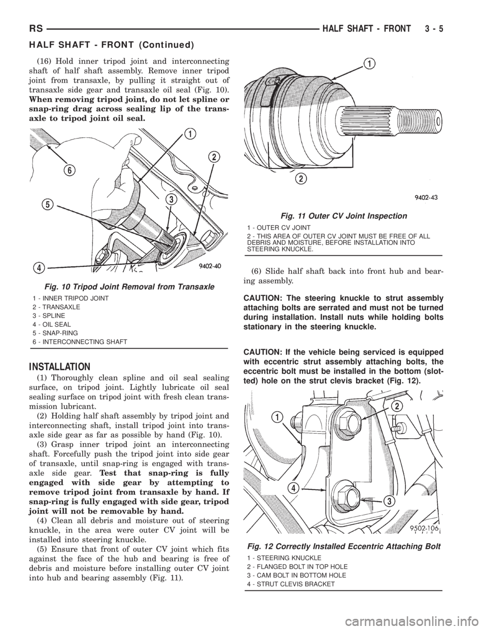
(16) Hold inner tripod joint and interconnecting
shaft of half shaft assembly. Remove inner tripod
joint from transaxle, by pulling it straight out of
transaxle side gear and transaxle oil seal (Fig. 10).
When removing tripod joint, do not let spline or
snap-ring drag across sealing lip of the trans-
axle to tripod joint oil seal.
INSTALLATION
(1) Thoroughly clean spline and oil seal sealing
surface, on tripod joint. Lightly lubricate oil seal
sealing surface on tripod joint with fresh clean trans-
mission lubricant.
(2) Holding half shaft assembly by tripod joint and
interconnecting shaft, install tripod joint into trans-
axle side gear as far as possible by hand (Fig. 10).
(3) Grasp inner tripod joint an interconnecting
shaft. Forcefully push the tripod joint into side gear
of transaxle, until snap-ring is engaged with trans-
axle side gear.Test that snap-ring is fully
engaged with side gear by attempting to
remove tripod joint from transaxle by hand. If
snap-ring is fully engaged with side gear, tripod
joint will not be removable by hand.
(4) Clean all debris and moisture out of steering
knuckle, in the area were outer CV joint will be
installed into steering knuckle.
(5) Ensure that front of outer CV joint which fits
against the face of the hub and bearing is free of
debris and moisture before installing outer CV joint
into hub and bearing assembly (Fig. 11).(6) Slide half shaft back into front hub and bear-
ing assembly.
CAUTION: The steering knuckle to strut assembly
attaching bolts are serrated and must not be turned
during installation. Install nuts while holding bolts
stationary in the steering knuckle.
CAUTION: If the vehicle being serviced is equipped
with eccentric strut assembly attaching bolts, the
eccentric bolt must be installed in the bottom (slot-
ted) hole on the strut clevis bracket (Fig. 12).
Fig. 10 Tripod Joint Removal from Transaxle
1 - INNER TRIPOD JOINT
2 - TRANSAXLE
3 - SPLINE
4 - OIL SEAL
5 - SNAP-RING
6 - INTERCONNECTING SHAFT
Fig. 11 Outer CV Joint Inspection
1 - OUTER CV JOINT
2 - THIS AREA OF OUTER CV JOINT MUST BE FREE OF ALL
DEBRIS AND MOISTURE, BEFORE INSTALLATION INTO
STEERING KNUCKLE.
Fig. 12 Correctly Installed Eccentric Attaching Bolt
1 - STEERING KNUCKLE
2 - FLANGED BOLT IN TOP HOLE
3 - CAM BOLT IN BOTTOM HOLE
4 - STRUT CLEVIS BRACKET
RSHALF SHAFT - FRONT3-5
HALF SHAFT - FRONT (Continued)
Page 1582 of 4284
(7) Install steering knuckle in clevis bracket of
strut damper assembly. Install the strut damper to
steering knuckle attaching bolts. Tighten both bolts
to a torque of 81 N´m (60 ft. lbs.) plus an additional
1/4 turn.
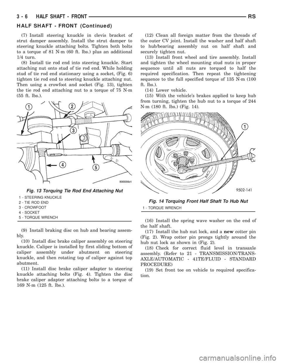
(8) Install tie rod end into steering knuckle. Start
attaching nut onto stud of tie rod end. While holding
stud of tie rod end stationary using a socket, (Fig. 6)
tighten tie rod end to steering knuckle attaching nut.
Then using a crowfoot and socket (Fig. 13), tighten
the tie rod end attaching nut to a torque of 75 N´m
(55 ft. lbs.).
(9) Install braking disc on hub and bearing assem-
bly.
(10) Install disc brake caliper assembly on steering
knuckle. Caliper is installed by first sliding bottom of
caliper assembly under abutment on steering
knuckle, and then rotating top of caliper against top
abutment.
(11) Install disc brake caliper adapter to steering
knuckle attaching bolts (Fig. 4). Tighten the disc
brake caliper adapter attaching bolts to a torque of
169 N´m (125 ft. lbs.).(12) Clean all foreign matter from the threads of
the outer CV joint. Install the washer and half shaft
to hub/bearing assembly nut on half shaft and
securely tighten nut.
(13) Install front wheel and tire assembly. Install
and tighten the wheel mounting stud nuts in proper
sequence until all nuts are torqued to half the
required specification. Then repeat the tightening
sequence to the full specified torque of 135 N´m (100
ft. lbs.).
(14) Lower vehicle.
(15) With the vehicle's brakes applied to keep hub
from turning, tighten the hub nut to a torque of 244
N´m (180 ft. lbs.) (Fig. 14).
(16) Install the spring wave washer on the end of
the half shaft.
(17) Install the hub nut lock, and anewcotter pin
(Fig. 2). Wrap cotter pin prongs tightly around the
hub nut lock as shown in (Fig. 2).
(18) Check for correct fluid level in transaxle
assembly. (Refer to 21 - TRANSMISSION/TRANS-
AXLE/AUTOMATIC - 41TE/FLUID - STANDARD
PROCEDURE)
(19) Set front toe on vehicle to required specifica-
tion.
Fig. 13 Torquing Tie Rod End Attaching Nut
1 - STEERING KNUCKLE
2 - TIE ROD END
3 - CROWFOOT
4 - SOCKET
5 - TORQUE WRENCHFig. 14 Torquing Front Half Shaft To Hub Nut
1 - TORQUE WRENCH
3 - 6 HALF SHAFT - FRONTRS
HALF SHAFT - FRONT (Continued)
Page 1583 of 4284
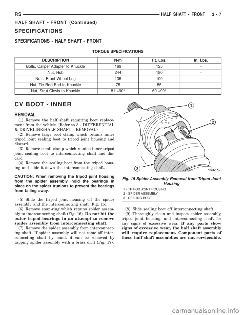
SPECIFICATIONS
SPECIFICATIONS - HALF SHAFT - FRONT
TORQUE SPECIFICATIONS
DESCRIPTION N´m Ft. Lbs. In. Lbs.
Bolts, Caliper Adapter to Knuckle 169 125 -
Nut, Hub 244 180 -
Nuts, Front Wheel Lug 135 100 -
Nut, Tie Rod End to Knuckle 75 55 -
Nut, Strut Clevis to Knuckle 81 +90É 60 +90É -
CV BOOT - INNER
REMOVAL
(1) Remove the half shaft requiring boot replace-
ment from the vehicle. (Refer to 3 - DIFFERENTIAL
& DRIVELINE/HALF SHAFT - REMOVAL)
(2) Remove large boot clamp which retains inner
tripod joint sealing boot to tripod joint housing and
discard.
(3) Remove small clamp which retains inner tripod
joint sealing boot to interconnecting shaft and dis-
card.
(4) Remove the sealing boot from the tripod hous-
ing and slide it down the interconnecting shaft.
CAUTION: When removing the tripod joint housing
from the spider assembly, hold the bearings in
place on the spider trunions to prevent the bearings
from falling away.
(5) Slide the tripod joint housing off the spider
assembly and the interconnecting shaft (Fig. 15).
(6) Remove snap-ring which retains spider assem-
bly to interconnecting shaft (Fig. 16).Do not hit the
outer tripod bearings in an attempt to remove
spider assembly from interconnecting shaft.
(7) Remove the spider assembly from interconnect-
ing shaft. If spider assembly will not come off inter-
connecting shaft by hand, it can be removed by
tapping spider assembly with a brass drift (Fig. 17).(8) Slide sealing boot off interconnecting shaft.
(9) Thoroughly clean and inspect spider assembly,
tripod joint housing, and interconnecting shaft for
any signs of excessive wear.If any parts show
signs of excessive wear, the half shaft assembly
will require replacement. Component parts of
these half shaft assemblies are not serviceable.
Fig. 15 Spider Assembly Removal from Tripod Joint
Housing
1 - TRIPOD JOINT HOUSING
2 - SPIDER ASSEMBLY
3 - SEALING BOOT
RSHALF SHAFT - FRONT3-7
HALF SHAFT - FRONT (Continued)
Page 1584 of 4284
INSTALLATION
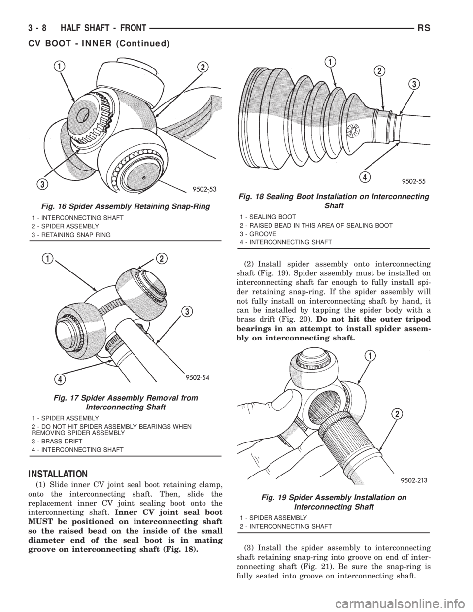
(1) Slide inner CV joint seal boot retaining clamp,
onto the interconnecting shaft. Then, slide the
replacement inner CV joint sealing boot onto the
interconnecting shaft.Inner CV joint seal boot
MUST be positioned on interconnecting shaft
so the raised bead on the inside of the small
diameter end of the seal boot is in mating
groove on interconnecting shaft (Fig. 18).(2) Install spider assembly onto interconnecting
shaft (Fig. 19). Spider assembly must be installed on
interconnecting shaft far enough to fully install spi-
der retaining snap-ring. If the spider assembly will
not fully install on interconnecting shaft by hand, it
can be installed by tapping the spider body with a
brass drift (Fig. 20).Do not hit the outer tripod
bearings in an attempt to install spider assem-
bly on interconnecting shaft.
(3) Install the spider assembly to interconnecting
shaft retaining snap-ring into groove on end of inter-
connecting shaft (Fig. 21). Be sure the snap-ring is
fully seated into groove on interconnecting shaft.
Fig. 16 Spider Assembly Retaining Snap-Ring
1 - INTERCONNECTING SHAFT
2 - SPIDER ASSEMBLY
3 - RETAINING SNAP RING
Fig. 17 Spider Assembly Removal from
Interconnecting Shaft
1 - SPIDER ASSEMBLY
2 - DO NOT HIT SPIDER ASSEMBLY BEARINGS WHEN
REMOVING SPIDER ASSEMBLY
3 - BRASS DRIFT
4 - INTERCONNECTING SHAFT
Fig. 18 Sealing Boot Installation on Interconnecting
Shaft
1 - SEALING BOOT
2 - RAISED BEAD IN THIS AREA OF SEALING BOOT
3 - GROOVE
4 - INTERCONNECTING SHAFT
Fig. 19 Spider Assembly Installation on
Interconnecting Shaft
1 - SPIDER ASSEMBLY
2 - INTERCONNECTING SHAFT
3 - 8 HALF SHAFT - FRONTRS
CV BOOT - INNER (Continued)
Page 1585 of 4284
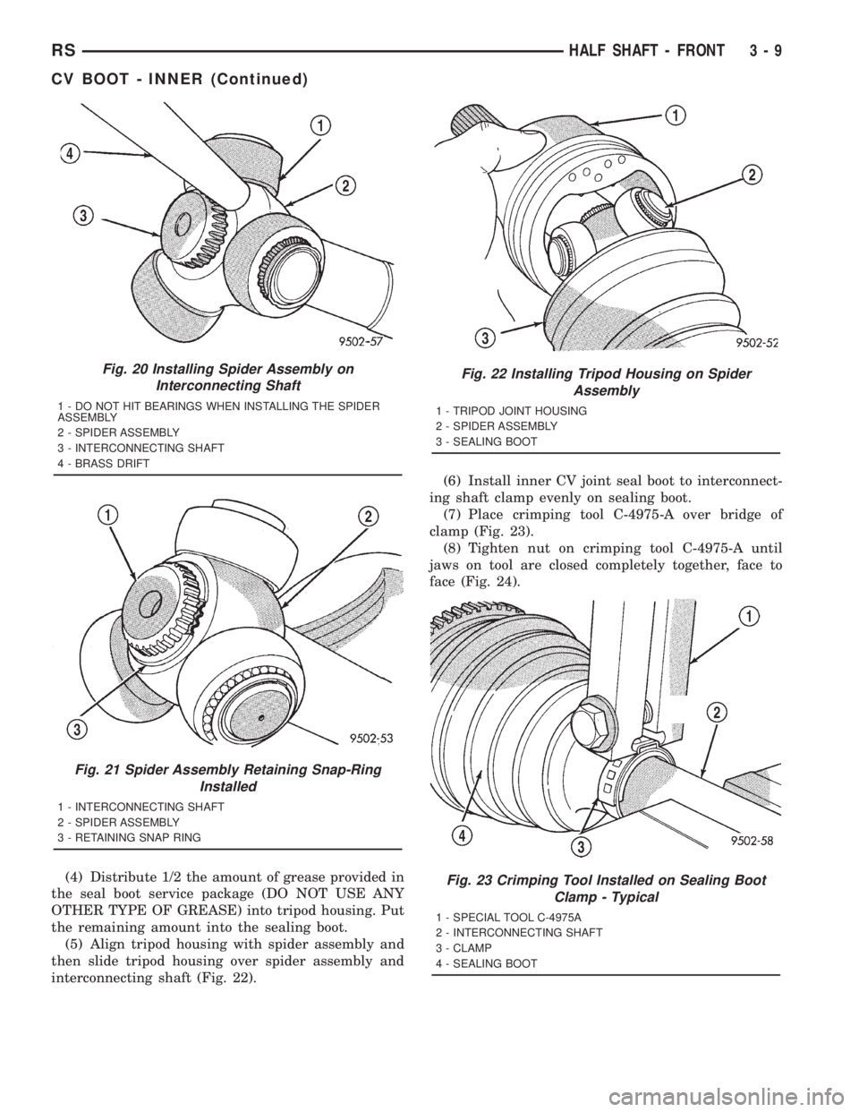
(4) Distribute 1/2 the amount of grease provided in
the seal boot service package (DO NOT USE ANY
OTHER TYPE OF GREASE) into tripod housing. Put
the remaining amount into the sealing boot.
(5) Align tripod housing with spider assembly and
then slide tripod housing over spider assembly and
interconnecting shaft (Fig. 22).(6) Install inner CV joint seal boot to interconnect-
ing shaft clamp evenly on sealing boot.
(7) Place crimping tool C-4975-A over bridge of
clamp (Fig. 23).
(8) Tighten nut on crimping tool C-4975-A until
jaws on tool are closed completely together, face to
face (Fig. 24).
Fig. 20 Installing Spider Assembly on
Interconnecting Shaft
1 - DO NOT HIT BEARINGS WHEN INSTALLING THE SPIDER
ASSEMBLY
2 - SPIDER ASSEMBLY
3 - INTERCONNECTING SHAFT
4 - BRASS DRIFT
Fig. 21 Spider Assembly Retaining Snap-Ring
Installed
1 - INTERCONNECTING SHAFT
2 - SPIDER ASSEMBLY
3 - RETAINING SNAP RING
Fig. 22 Installing Tripod Housing on Spider
Assembly
1 - TRIPOD JOINT HOUSING
2 - SPIDER ASSEMBLY
3 - SEALING BOOT
Fig. 23 Crimping Tool Installed on Sealing Boot
Clamp - Typical
1 - SPECIAL TOOL C-4975A
2 - INTERCONNECTING SHAFT
3 - CLAMP
4 - SEALING BOOT
RSHALF SHAFT - FRONT3-9
CV BOOT - INNER (Continued)
Page 1586 of 4284
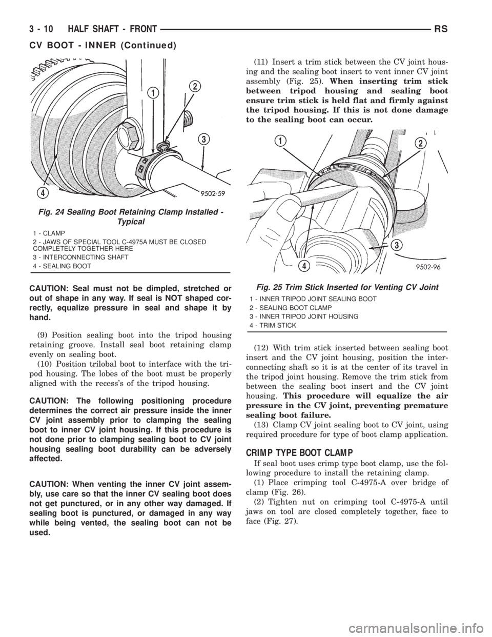
CAUTION: Seal must not be dimpled, stretched or
out of shape in any way. If seal is NOT shaped cor-
rectly, equalize pressure in seal and shape it by
hand.
(9) Position sealing boot into the tripod housing
retaining groove. Install seal boot retaining clamp
evenly on sealing boot.
(10) Position trilobal boot to interface with the tri-
pod housing. The lobes of the boot must be properly
aligned with the recess's of the tripod housing.
CAUTION: The following positioning procedure
determines the correct air pressure inside the inner
CV joint assembly prior to clamping the sealing
boot to inner CV joint housing. If this procedure is
not done prior to clamping sealing boot to CV joint
housing sealing boot durability can be adversely
affected.
CAUTION: When venting the inner CV joint assem-
bly, use care so that the inner CV sealing boot does
not get punctured, or in any other way damaged. If
sealing boot is punctured, or damaged in any way
while being vented, the sealing boot can not be
used.(11) Insert a trim stick between the CV joint hous-
ing and the sealing boot insert to vent inner CV joint
assembly (Fig. 25).When inserting trim stick
between tripod housing and sealing boot
ensure trim stick is held flat and firmly against
the tripod housing. If this is not done damage
to the sealing boot can occur.
(12) With trim stick inserted between sealing boot
insert and the CV joint housing, position the inter-
connecting shaft so it is at the center of its travel in
the tripod joint housing. Remove the trim stick from
between the sealing boot insert and the CV joint
housing.This procedure will equalize the air
pressure in the CV joint, preventing premature
sealing boot failure.
(13) Clamp CV joint sealing boot to CV joint, using
required procedure for type of boot clamp application.
CRIMP TYPE BOOT CLAMP
If seal boot uses crimp type boot clamp, use the fol-
lowing procedure to install the retaining clamp.
(1) Place crimping tool C-4975-A over bridge of
clamp (Fig. 26).
(2) Tighten nut on crimping tool C-4975-A until
jaws on tool are closed completely together, face to
face (Fig. 27).
Fig. 24 Sealing Boot Retaining Clamp Installed -
Typical
1 - CLAMP
2 - JAWS OF SPECIAL TOOL C-4975A MUST BE CLOSED
COMPLETELY TOGETHER HERE
3 - INTERCONNECTING SHAFT
4 - SEALING BOOT
Fig. 25 Trim Stick Inserted for Venting CV Joint
1 - INNER TRIPOD JOINT SEALING BOOT
2 - SEALING BOOT CLAMP
3 - INNER TRIPOD JOINT HOUSING
4 - TRIM STICK
3 - 10 HALF SHAFT - FRONTRS
CV BOOT - INNER (Continued)
Page 1587 of 4284
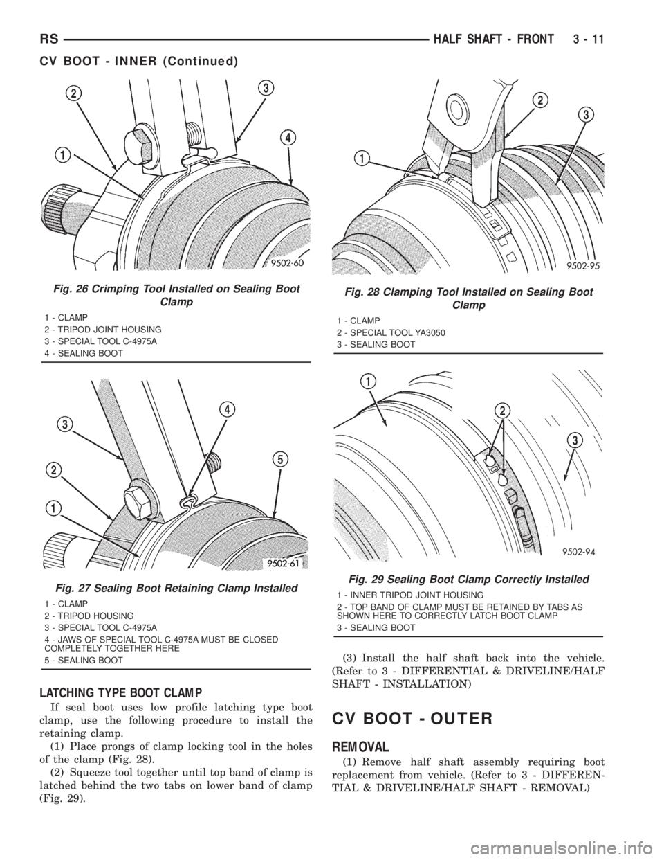
LATCHING TYPE BOOT CLAMP
If seal boot uses low profile latching type boot
clamp, use the following procedure to install the
retaining clamp.
(1) Place prongs of clamp locking tool in the holes
of the clamp (Fig. 28).
(2) Squeeze tool together until top band of clamp is
latched behind the two tabs on lower band of clamp
(Fig. 29).(3) Install the half shaft back into the vehicle.
(Refer to 3 - DIFFERENTIAL & DRIVELINE/HALF
SHAFT - INSTALLATION)
CV BOOT - OUTER
REMOVAL
(1) Remove half shaft assembly requiring boot
replacement from vehicle. (Refer to 3 - DIFFEREN-
TIAL & DRIVELINE/HALF SHAFT - REMOVAL)
Fig. 26 Crimping Tool Installed on Sealing Boot
Clamp
1 - CLAMP
2 - TRIPOD JOINT HOUSING
3 - SPECIAL TOOL C-4975A
4 - SEALING BOOT
Fig. 27 Sealing Boot Retaining Clamp Installed
1 - CLAMP
2 - TRIPOD HOUSING
3 - SPECIAL TOOL C-4975A
4 - JAWS OF SPECIAL TOOL C-4975A MUST BE CLOSED
COMPLETELY TOGETHER HERE
5 - SEALING BOOT
Fig. 28 Clamping Tool Installed on Sealing Boot
Clamp
1 - CLAMP
2 - SPECIAL TOOL YA3050
3 - SEALING BOOT
Fig. 29 Sealing Boot Clamp Correctly Installed
1 - INNER TRIPOD JOINT HOUSING
2 - TOP BAND OF CLAMP MUST BE RETAINED BY TABS AS
SHOWN HERE TO CORRECTLY LATCH BOOT CLAMP
3 - SEALING BOOT
RSHALF SHAFT - FRONT3-11
CV BOOT - INNER (Continued)
Page 1588 of 4284
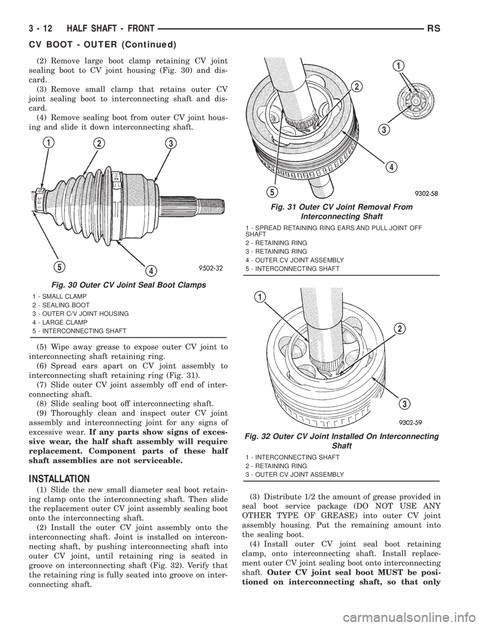
(2) Remove large boot clamp retaining CV joint
sealing boot to CV joint housing (Fig. 30) and dis-
card.
(3) Remove small clamp that retains outer CV
joint sealing boot to interconnecting shaft and dis-
card.
(4) Remove sealing boot from outer CV joint hous-
ing and slide it down interconnecting shaft.
(5) Wipe away grease to expose outer CV joint to
interconnecting shaft retaining ring.
(6) Spread ears apart on CV joint assembly to
interconnecting shaft retaining ring (Fig. 31).
(7) Slide outer CV joint assembly off end of inter-
connecting shaft.
(8) Slide sealing boot off interconnecting shaft.
(9) Thoroughly clean and inspect outer CV joint
assembly and interconnecting joint for any signs of
excessive wear.If any parts show signs of exces-
sive wear, the half shaft assembly will require
replacement. Component parts of these half
shaft assemblies are not serviceable.
INSTALLATION
(1) Slide the new small diameter seal boot retain-
ing clamp onto the interconnecting shaft. Then slide
the replacement outer CV joint assembly sealing boot
onto the interconnecting shaft.
(2) Install the outer CV joint assembly onto the
interconnecting shaft. Joint is installed on intercon-
necting shaft, by pushing interconnecting shaft into
outer CV joint, until retaining ring is seated in
groove on interconnecting shaft (Fig. 32). Verify that
the retaining ring is fully seated into groove on inter-
connecting shaft.(3) Distribute 1/2 the amount of grease provided in
seal boot service package (DO NOT USE ANY
OTHER TYPE OF GREASE) into outer CV joint
assembly housing. Put the remaining amount into
the sealing boot.
(4) Install outer CV joint seal boot retaining
clamp, onto interconnecting shaft. Install replace-
ment outer CV joint sealing boot onto interconnecting
shaft.Outer CV joint seal boot MUST be posi-
tioned on interconnecting shaft, so that only
Fig. 30 Outer CV Joint Seal Boot Clamps
1 - SMALL CLAMP
2 - SEALING BOOT
3 - OUTER C/V JOINT HOUSING
4 - LARGE CLAMP
5 - INTERCONNECTING SHAFT
Fig. 31 Outer CV Joint Removal From
Interconnecting Shaft
1 - SPREAD RETAINING RING EARS AND PULL JOINT OFF
SHAFT
2 - RETAINING RING
3 - RETAINING RING
4 - OUTER CV JOINT ASSEMBLY
5 - INTERCONNECTING SHAFT
Fig. 32 Outer CV Joint Installed On Interconnecting
Shaft
1 - INTERCONNECTING SHAFT
2 - RETAINING RING
3 - OUTER CV JOINT ASSEMBLY
3 - 12 HALF SHAFT - FRONTRS
CV BOOT - OUTER (Continued)
Page 1589 of 4284
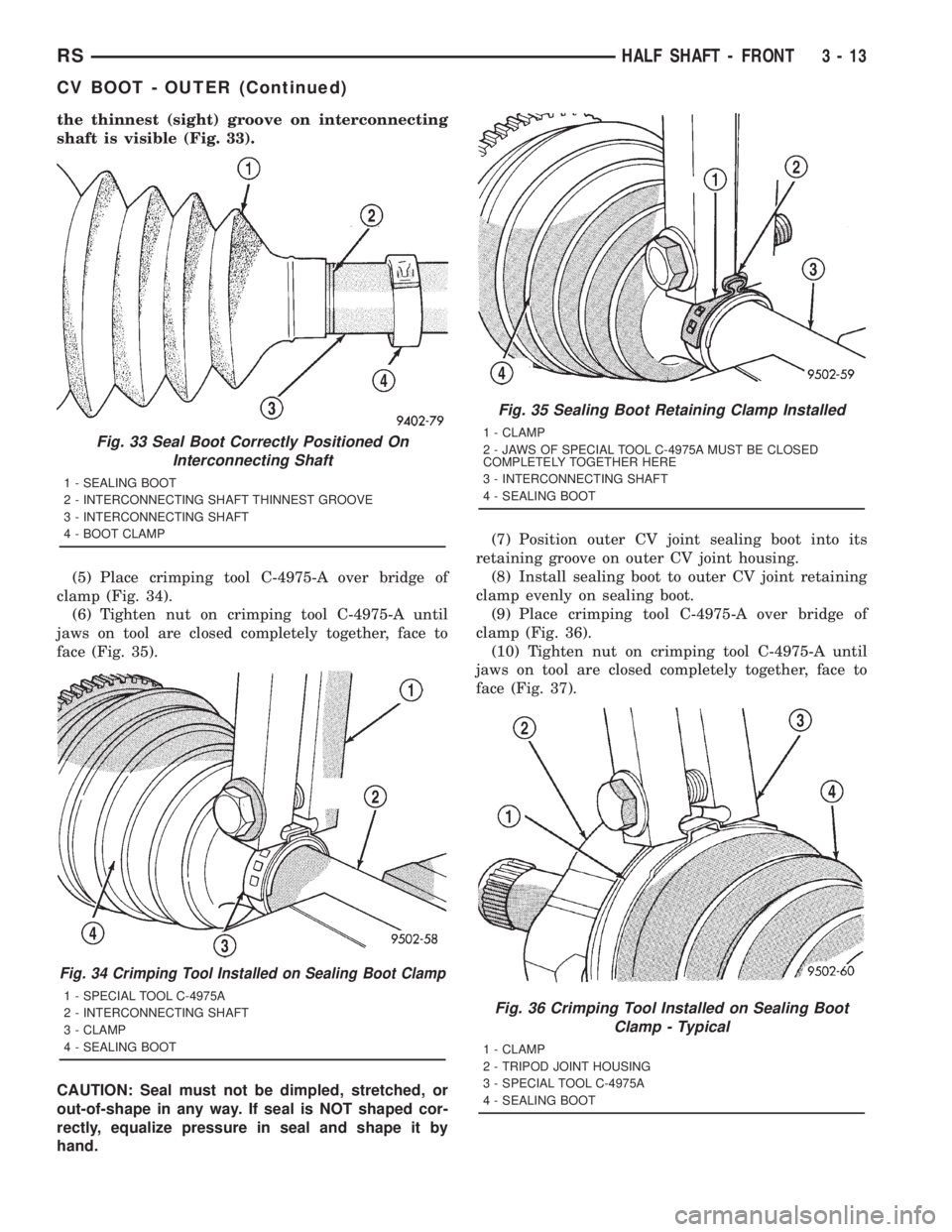
the thinnest (sight) groove on interconnecting
shaft is visible (Fig. 33).
(5) Place crimping tool C-4975-A over bridge of
clamp (Fig. 34).
(6) Tighten nut on crimping tool C-4975-A until
jaws on tool are closed completely together, face to
face (Fig. 35).
CAUTION: Seal must not be dimpled, stretched, or
out-of-shape in any way. If seal is NOT shaped cor-
rectly, equalize pressure in seal and shape it by
hand.(7) Position outer CV joint sealing boot into its
retaining groove on outer CV joint housing.
(8) Install sealing boot to outer CV joint retaining
clamp evenly on sealing boot.
(9) Place crimping tool C-4975-A over bridge of
clamp (Fig. 36).
(10) Tighten nut on crimping tool C-4975-A until
jaws on tool are closed completely together, face to
face (Fig. 37).
Fig. 33 Seal Boot Correctly Positioned On
Interconnecting Shaft
1 - SEALING BOOT
2 - INTERCONNECTING SHAFT THINNEST GROOVE
3 - INTERCONNECTING SHAFT
4 - BOOT CLAMP
Fig. 34 Crimping Tool Installed on Sealing Boot Clamp
1 - SPECIAL TOOL C-4975A
2 - INTERCONNECTING SHAFT
3 - CLAMP
4 - SEALING BOOT
Fig. 35 Sealing Boot Retaining Clamp Installed
1 - CLAMP
2 - JAWS OF SPECIAL TOOL C-4975A MUST BE CLOSED
COMPLETELY TOGETHER HERE
3 - INTERCONNECTING SHAFT
4 - SEALING BOOT
Fig. 36 Crimping Tool Installed on Sealing Boot
Clamp - Typical
1 - CLAMP
2 - TRIPOD JOINT HOUSING
3 - SPECIAL TOOL C-4975A
4 - SEALING BOOT
RSHALF SHAFT - FRONT3-13
CV BOOT - OUTER (Continued)
Page 1590 of 4284
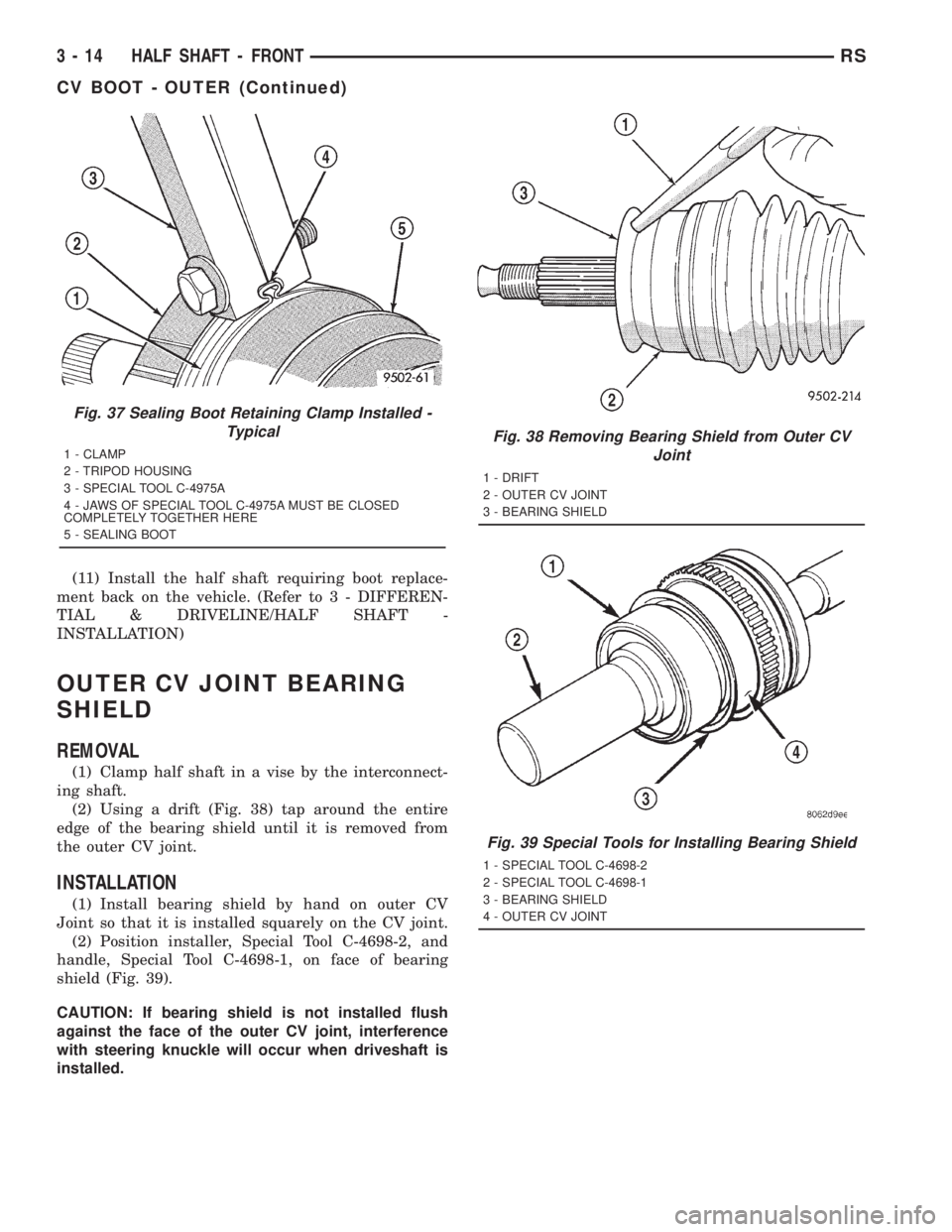
(11) Install the half shaft requiring boot replace-
ment back on the vehicle. (Refer to 3 - DIFFEREN-
TIAL & DRIVELINE/HALF SHAFT -
INSTALLATION)
OUTER CV JOINT BEARING
SHIELD
REMOVAL
(1) Clamp half shaft in a vise by the interconnect-
ing shaft.
(2) Using a drift (Fig. 38) tap around the entire
edge of the bearing shield until it is removed from
the outer CV joint.
INSTALLATION
(1) Install bearing shield by hand on outer CV
Joint so that it is installed squarely on the CV joint.
(2) Position installer, Special Tool C-4698-2, and
handle, Special Tool C-4698-1, on face of bearing
shield (Fig. 39).
CAUTION: If bearing shield is not installed flush
against the face of the outer CV joint, interference
with steering knuckle will occur when driveshaft is
installed.
Fig. 37 Sealing Boot Retaining Clamp Installed -
Typical
1 - CLAMP
2 - TRIPOD HOUSING
3 - SPECIAL TOOL C-4975A
4 - JAWS OF SPECIAL TOOL C-4975A MUST BE CLOSED
COMPLETELY TOGETHER HERE
5 - SEALING BOOT
Fig. 38 Removing Bearing Shield from Outer CV
Joint
1 - DRIFT
2 - OUTER CV JOINT
3 - BEARING SHIELD
Fig. 39 Special Tools for Installing Bearing Shield
1 - SPECIAL TOOL C-4698-2
2 - SPECIAL TOOL C-4698-1
3 - BEARING SHIELD
4 - OUTER CV JOINT
3 - 14 HALF SHAFT - FRONTRS
CV BOOT - OUTER (Continued)