transmission CHRYSLER VOYAGER 2001 Service Manual
[x] Cancel search | Manufacturer: CHRYSLER, Model Year: 2001, Model line: VOYAGER, Model: CHRYSLER VOYAGER 2001Pages: 4284, PDF Size: 83.53 MB
Page 7 of 4284
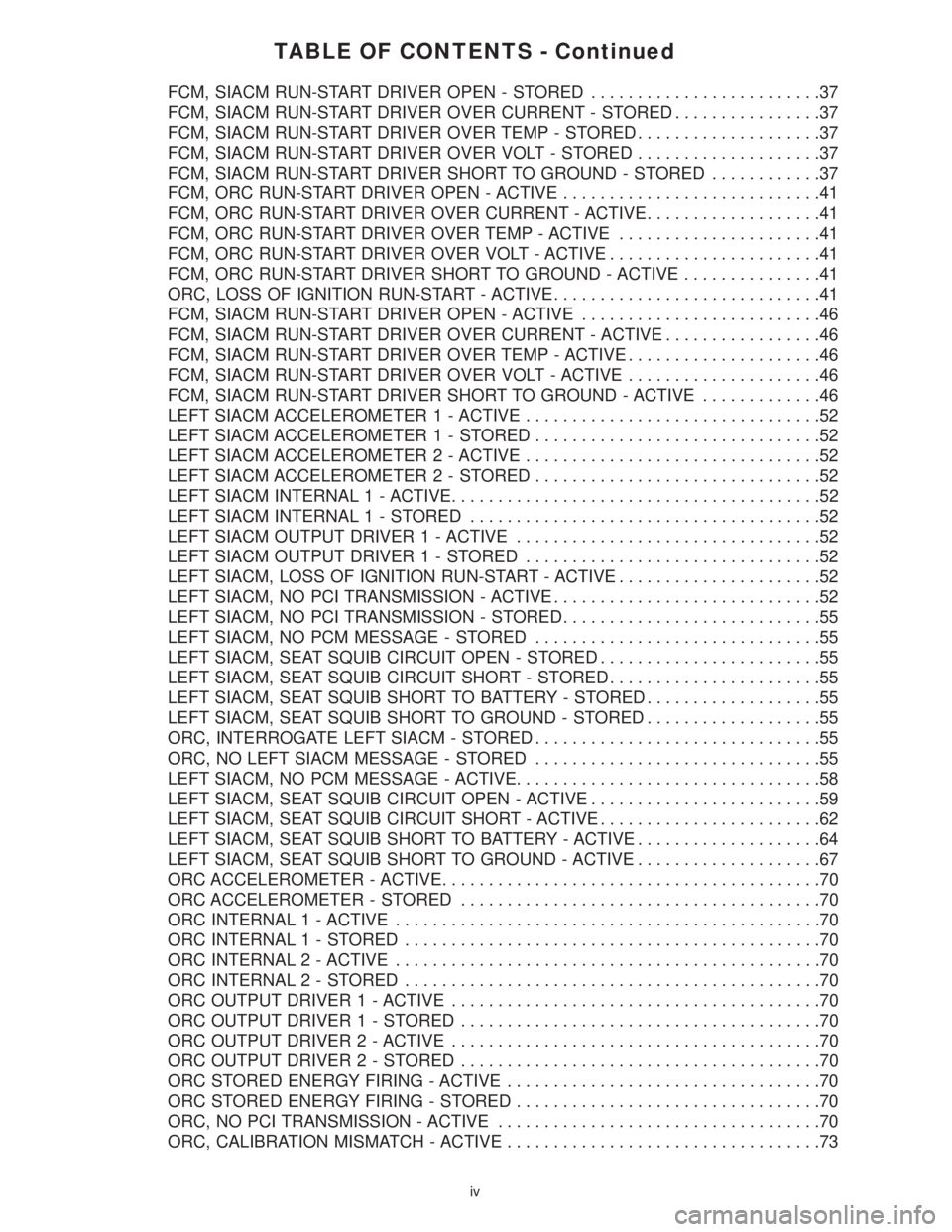
TABLE OF CONTENTS - Continued
FCM, SIACM RUN-START DRIVER OPEN - STORED.........................37
FCM, SIACM RUN-START DRIVER OVER CURRENT - STORED................37
FCM, SIACM RUN-START DRIVER OVER TEMP - STORED....................37
FCM, SIACM RUN-START DRIVER OVER VOLT - STORED....................37
FCM, SIACM RUN-START DRIVER SHORT TO GROUND - STORED............37
FCM, ORC RUN-START DRIVER OPEN - ACTIVE............................41
FCM, ORC RUN-START DRIVER OVER CURRENT - ACTIVE...................41
FCM, ORC RUN-START DRIVER OVER TEMP - ACTIVE......................41
FCM, ORC RUN-START DRIVER OVER VOLT - ACTIVE.......................41
FCM, ORC RUN-START DRIVER SHORT TO GROUND - ACTIVE...............41
ORC, LOSS OF IGNITION RUN-START - ACTIVE.............................41
FCM, SIACM RUN-START DRIVER OPEN - ACTIVE..........................46
FCM, SIACM RUN-START DRIVER OVER CURRENT - ACTIVE.................46
FCM, SIACM RUN-START DRIVER OVER TEMP - ACTIVE.....................46
FCM, SIACM RUN-START DRIVER OVER VOLT - ACTIVE.....................46
FCM, SIACM RUN-START DRIVER SHORT TO GROUND - ACTIVE.............46
LEFT SIACM ACCELEROMETER 1 - ACTIVE................................52
LEFT SIACM ACCELEROMETER1-STORED...............................52
LEFT SIACM ACCELEROMETER 2 - ACTIVE................................52
LEFT SIACM ACCELEROMETER2-STORED...............................52
LEFT SIACM INTERNAL 1 - ACTIVE........................................52
LEFT SIACM INTERNAL 1 - STORED......................................52
LEFT SIACM OUTPUT DRIVER 1 - ACTIVE.................................52
LEFT SIACM OUTPUT DRIVER1-STORED................................52
LEFT SIACM, LOSS OF IGNITION RUN-START - ACTIVE......................52
LEFT SIACM, NO PCI TRANSMISSION - ACTIVE.............................52
LEFT SIACM, NO PCI TRANSMISSION - STORED............................55
LEFT SIACM, NO PCM MESSAGE - STORED...............................55
LEFT SIACM, SEAT SQUIB CIRCUIT OPEN - STORED........................55
LEFT SIACM, SEAT SQUIB CIRCUIT SHORT - STORED.......................55
LEFT SIACM, SEAT SQUIB SHORT TO BATTERY - STORED...................55
LEFT SIACM, SEAT SQUIB SHORT TO GROUND - STORED...................55
ORC, INTERROGATE LEFT SIACM - STORED...............................55
ORC, NO LEFT SIACM MESSAGE - STORED...............................55
LEFT SIACM, NO PCM MESSAGE - ACTIVE.................................58
LEFT SIACM, SEAT SQUIB CIRCUIT OPEN - ACTIVE.........................59
LEFT SIACM, SEAT SQUIB CIRCUIT SHORT - ACTIVE........................62
LEFT SIACM, SEAT SQUIB SHORT TO BATTERY - ACTIVE....................64
LEFT SIACM, SEAT SQUIB SHORT TO GROUND - ACTIVE....................67
ORC ACCELEROMETER - ACTIVE.........................................70
ORC ACCELEROMETER - STORED.......................................70
ORC INTERNAL 1 - ACTIVE..............................................70
ORC INTERNAL 1 - STORED.............................................70
ORC INTERNAL 2 - ACTIVE..............................................70
ORC INTERNAL 2 - STORED.............................................70
ORC OUTPUT DRIVER 1 - ACTIVE........................................70
ORC OUTPUT DRIVER1-STORED.......................................70
ORC OUTPUT DRIVER 2 - ACTIVE........................................70
ORC OUTPUT DRIVER2-STORED.......................................70
ORC STORED ENERGY FIRING - ACTIVE..................................70
ORC STORED ENERGY FIRING - STORED.................................70
ORC, NO PCI TRANSMISSION - ACTIVE...................................70
ORC, CALIBRATION MISMATCH - ACTIVE..................................73
iv
Page 9 of 4284
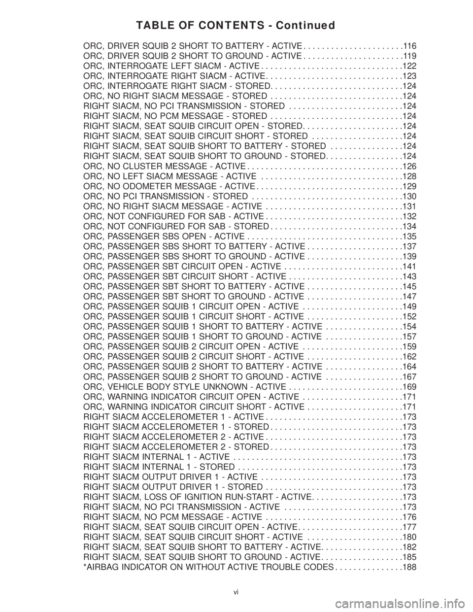
TABLE OF CONTENTS - Continued
ORC, DRIVER SQUIB 2 SHORT TO BATTERY - ACTIVE......................116
ORC, DRIVER SQUIB 2 SHORT TO GROUND - ACTIVE......................119
ORC, INTERROGATE LEFT SIACM - ACTIVE...............................122
ORC, INTERROGATE RIGHT SIACM - ACTIVE..............................123
ORC, INTERROGATE RIGHT SIACM - STORED.............................124
ORC, NO RIGHT SIACM MESSAGE - STORED.............................124
RIGHT SIACM, NO PCI TRANSMISSION - STORED.........................124
RIGHT SIACM, NO PCM MESSAGE - STORED.............................124
RIGHT SIACM, SEAT SQUIB CIRCUIT OPEN - STORED......................124
RIGHT SIACM, SEAT SQUIB CIRCUIT SHORT - STORED....................124
RIGHT SIACM, SEAT SQUIB SHORT TO BATTERY - STORED................124
RIGHT SIACM, SEAT SQUIB SHORT TO GROUND - STORED.................124
ORC, NO CLUSTER MESSAGE - ACTIVE..................................126
ORC, NO LEFT SIACM MESSAGE - ACTIVE...............................128
ORC, NO ODOMETER MESSAGE - ACTIVE................................129
ORC, NO PCI TRANSMISSION - STORED.................................130
ORC, NO RIGHT SIACM MESSAGE - ACTIVE..............................131
ORC, NOT CONFIGURED FOR SAB - ACTIVE..............................132
ORC, NOT CONFIGURED FOR SAB - STORED.............................134
ORC, PASSENGER SBS OPEN - ACTIVE..................................135
ORC, PASSENGER SBS SHORT TO BATTERY - ACTIVE.....................137
ORC, PASSENGER SBS SHORT TO GROUND - ACTIVE.....................139
ORC, PASSENGER SBT CIRCUIT OPEN - ACTIVE..........................141
ORC, PASSENGER SBT CIRCUIT SHORT - ACTIVE.........................143
ORC, PASSENGER SBT SHORT TO BATTERY - ACTIVE.....................145
ORC, PASSENGER SBT SHORT TO GROUND - ACTIVE.....................147
ORC, PASSENGER SQUIB 1 CIRCUIT OPEN - ACTIVE......................149
ORC, PASSENGER SQUIB 1 CIRCUIT SHORT - ACTIVE.....................152
ORC, PASSENGER SQUIB 1 SHORT TO BATTERY - ACTIVE.................154
ORC, PASSENGER SQUIB 1 SHORT TO GROUND - ACTIVE.................157
ORC, PASSENGER SQUIB 2 CIRCUIT OPEN - ACTIVE......................159
ORC, PASSENGER SQUIB 2 CIRCUIT SHORT - ACTIVE.....................162
ORC, PASSENGER SQUIB 2 SHORT TO BATTERY - ACTIVE.................164
ORC, PASSENGER SQUIB 2 SHORT TO GROUND - ACTIVE.................167
ORC, VEHICLE BODY STYLE UNKNOWN - ACTIVE.........................169
ORC, WARNING INDICATOR CIRCUIT OPEN - ACTIVE......................171
ORC, WARNING INDICATOR CIRCUIT SHORT - ACTIVE.....................171
RIGHT SIACM ACCELEROMETER 1 - ACTIVE..............................173
RIGHT SIACM ACCELEROMETER1-STORED.............................173
RIGHT SIACM ACCELEROMETER 2 - ACTIVE..............................173
RIGHT SIACM ACCELEROMETER2-STORED.............................173
RIGHT SIACM INTERNAL 1 - ACTIVE.....................................173
RIGHT SIACM INTERNAL 1 - STORED....................................173
RIGHT SIACM OUTPUT DRIVER 1 - ACTIVE...............................173
RIGHT SIACM OUTPUT DRIVER1-STORED..............................173
RIGHT SIACM, LOSS OF IGNITION RUN-START - ACTIVE....................173
RIGHT SIACM, NO PCI TRANSMISSION - ACTIVE..........................173
RIGHT SIACM, NO PCM MESSAGE - ACTIVE..............................176
RIGHT SIACM, SEAT SQUIB CIRCUIT OPEN - ACTIVE.......................177
RIGHT SIACM, SEAT SQUIB CIRCUIT SHORT - ACTIVE.....................180
RIGHT SIACM, SEAT SQUIB SHORT TO BATTERY - ACTIVE..................182
RIGHT SIACM, SEAT SQUIB SHORT TO GROUND - ACTIVE..................185
*AIRBAG INDICATOR ON WITHOUT ACTIVE TROUBLE CODES...............188
vi
Page 14 of 4284
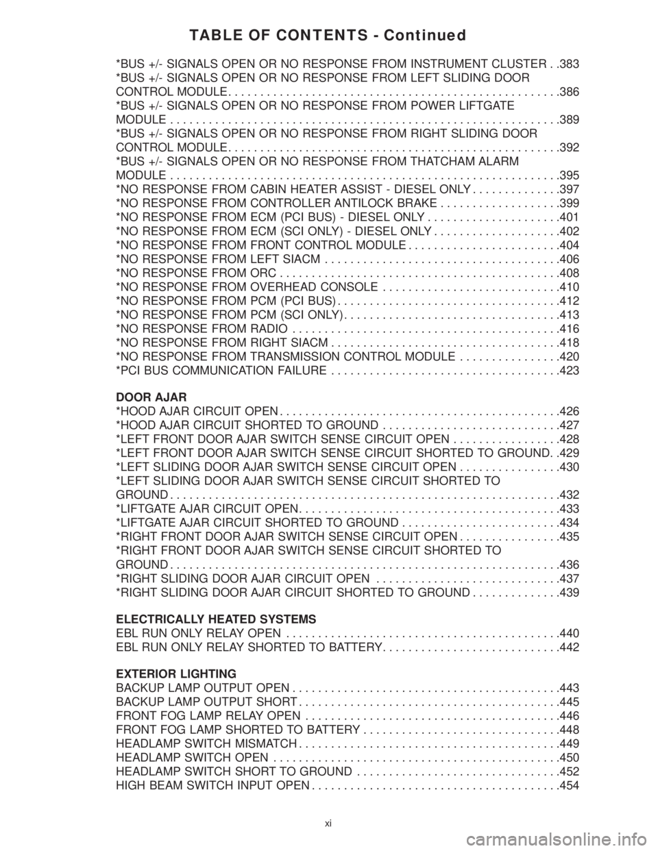
TABLE OF CONTENTS - Continued
*BUS +/- SIGNALS OPEN OR NO RESPONSE FROM INSTRUMENT CLUSTER . .383
*BUS +/- SIGNALS OPEN OR NO RESPONSE FROM LEFT SLIDING DOOR
CONTROL MODULE....................................................386
*BUS +/- SIGNALS OPEN OR NO RESPONSE FROM POWER LIFTGATE
MODULE.............................................................389
*BUS +/- SIGNALS OPEN OR NO RESPONSE FROM RIGHT SLIDING DOOR
CONTROL MODULE....................................................392
*BUS +/- SIGNALS OPEN OR NO RESPONSE FROM THATCHAM ALARM
MODULE.............................................................395
*NO RESPONSE FROM CABIN HEATER ASSIST - DIESEL ONLY..............397
*NO RESPONSE FROM CONTROLLER ANTILOCK BRAKE...................399
*NO RESPONSE FROM ECM (PCI BUS) - DIESEL ONLY.....................401
*NO RESPONSE FROM ECM (SCI ONLY) - DIESEL ONLY....................402
*NO RESPONSE FROM FRONT CONTROL MODULE........................404
*NO RESPONSE FROM LEFT SIACM.....................................406
*NO RESPONSE FROM ORC............................................408
*NO RESPONSE FROM OVERHEAD CONSOLE............................410
*NO RESPONSE FROM PCM (PCI BUS)...................................412
*NO RESPONSE FROM PCM (SCI ONLY)..................................413
*NO RESPONSE FROM RADIO..........................................416
*NO RESPONSE FROM RIGHT SIACM....................................418
*NO RESPONSE FROM TRANSMISSION CONTROL MODULE................420
*PCI BUS COMMUNICATION FAILURE....................................423
DOOR AJAR
*HOOD AJAR CIRCUIT OPEN............................................426
*HOOD AJAR CIRCUIT SHORTED TO GROUND............................427
*LEFT FRONT DOOR AJAR SWITCH SENSE CIRCUIT OPEN.................428
*LEFT FRONT DOOR AJAR SWITCH SENSE CIRCUIT SHORTED TO GROUND. .429
*LEFT SLIDING DOOR AJAR SWITCH SENSE CIRCUIT OPEN................430
*LEFT SLIDING DOOR AJAR SWITCH SENSE CIRCUIT SHORTED TO
GROUND.............................................................432
*LIFTGATE AJAR CIRCUIT OPEN.........................................433
*LIFTGATE AJAR CIRCUIT SHORTED TO GROUND.........................434
*RIGHT FRONT DOOR AJAR SWITCH SENSE CIRCUIT OPEN................435
*RIGHT FRONT DOOR AJAR SWITCH SENSE CIRCUIT SHORTED TO
GROUND.............................................................436
*RIGHT SLIDING DOOR AJAR CIRCUIT OPEN.............................437
*RIGHT SLIDING DOOR AJAR CIRCUIT SHORTED TO GROUND..............439
ELECTRICALLY HEATED SYSTEMS
EBL RUN ONLY RELAY OPEN...........................................440
EBL RUN ONLY RELAY SHORTED TO BATTERY............................442
EXTERIOR LIGHTING
BACKUP LAMP OUTPUT OPEN..........................................443
BACKUP LAMP OUTPUT SHORT.........................................445
FRONT FOG LAMP RELAY OPEN........................................446
FRONT FOG LAMP SHORTED TO BATTERY...............................448
HEADLAMP SWITCH MISMATCH.........................................449
HEADLAMP SWITCH OPEN.............................................450
HEADLAMP SWITCH SHORT TO GROUND................................452
HIGH BEAM SWITCH INPUT OPEN.......................................454
xi
Page 27 of 4284
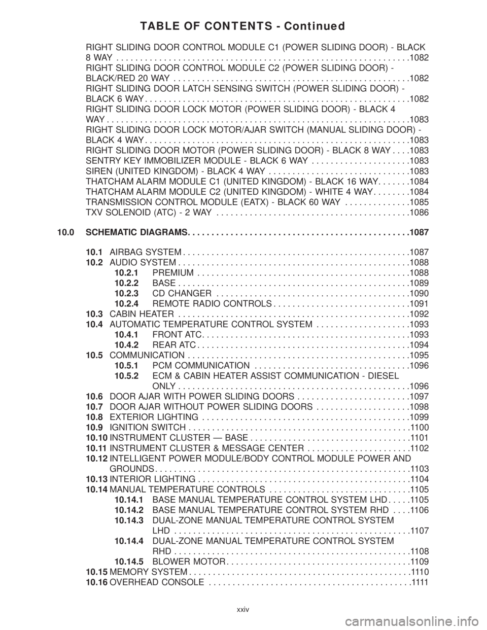
TABLE OF CONTENTS - Continued
RIGHT SLIDING DOOR CONTROL MODULE C1 (POWER SLIDING DOOR) - BLACK
8 WAY ..............................................................1082
RIGHT SLIDING DOOR CONTROL MODULE C2 (POWER SLIDING DOOR) -
BLACK/RED 20 WAY..................................................1082
RIGHT SLIDING DOOR LATCH SENSING SWITCH (POWER SLIDING DOOR) -
BLACK 6 WAY........................................................1082
RIGHT SLIDING DOOR LOCK MOTOR (POWER SLIDING DOOR) - BLACK 4
WAY................................................................1083
RIGHT SLIDING DOOR LOCK MOTOR/AJAR SWITCH (MANUAL SLIDING DOOR) -
BLACK 4 WAY........................................................1083
RIGHT SLIDING DOOR MOTOR (POWER SLIDING DOOR) - BLACK 8 WAY. . . .1083
SENTRY KEY IMMOBILIZER MODULE - BLACK 6 WAY.....................1083
SIREN (UNITED KINGDOM) - BLACK 4 WAY..............................1083
THATCHAM ALARM MODULE C1 (UNITED KINGDOM) - BLACK 16 WAY.......1084
THATCHAM ALARM MODULE C2 (UNITED KINGDOM) - WHITE 4 WAY........1084
TRANSMISSION CONTROL MODULE (EATX) - BLACK 60 WAY..............1085
TXV SOLENOID (ATC)-2WAY.........................................1086
10.0 SCHEMATIC DIAGRAMS...............................................1087
10.1AIRBAG SYSTEM................................................1087
10.2AUDIO SYSTEM.................................................1088
10.2.1PREMIUM.............................................1088
10.2.2BASE.................................................1089
10.2.3CD CHANGER.........................................1090
10.2.4REMOTE RADIO CONTROLS.............................1091
10.3CABIN HEATER.................................................1092
10.4AUTOMATIC TEMPERATURE CONTROL SYSTEM....................1093
10.4.1FRONT ATC............................................1093
10.4.2REAR ATC.............................................1094
10.5COMMUNICATION...............................................1095
10.5.1PCM COMMUNICATION.................................1096
10.5.2ECM & CABIN HEATER ASSIST COMMUNICATION - DIESEL
ONLY.................................................1096
10.6DOOR AJAR WITH POWER SLIDING DOORS........................1097
10.7DOOR AJAR WITHOUT POWER SLIDING DOORS....................1098
10.8EXTERIOR LIGHTING............................................1099
10.9IGNITION SWITCH...............................................1100
10.10INSTRUMENT CLUSTER Ð BASE..................................1101
10.11INSTRUMENT CLUSTER & MESSAGE CENTER......................1102
10.12INTELLIGENT POWER MODULE/BODY CONTROL MODULE POWER AND
GROUNDS......................................................1103
10.13INTERIOR LIGHTING.............................................1104
10.14MANUAL TEMPERATURE CONTROLS..............................1105
10.14.1BASE MANUAL TEMPERATURE CONTROL SYSTEM LHD.....1105
10.14.2BASE MANUAL TEMPERATURE CONTROL SYSTEM RHD....1106
10.14.3DUAL-ZONE MANUAL TEMPERATURE CONTROL SYSTEM
LHD ..................................................1107
10.14.4DUAL-ZONE MANUAL TEMPERATURE CONTROL SYSTEM
RHD..................................................1108
10.14.5BLOWER MOTOR.......................................1109
10.15MEMORY SYSTEM...............................................1110
10.16OVERHEAD CONSOLE...........................................1111
xxiv
Page 31 of 4284
mitted on the bus even though a module may not
require all information to perform its function. It
will only respond to messages ªaddressedº to it
through binary coding process. This method of data
transmission significantly reduces the complexity
of the wiring in the vehicle and the size of wiring
harnesses. All of the information about the func-
tioning of all the systems is organized, controlled,
and communicated by the PCI bus, which is de-
scribed in the Communication Section of this gen-
eral information.
3.1 AIRBAG SYSTEM/OCCUPANT
RESTRAINT CONTROLLER SYSTEM
The 2001 Minivan Airbag System contain the
following components: Occupant Restraint Control-
ler (ORC), Airbag Warning Indicator, Clockspring,
Driver and Passenger Airbags, Seat belt Tensioners
(SBT), Hall-effect Seat Belt Switches (SBS), Left
and Right Side Airbag Control Module (SIACM),
and Seat (mounted side) Airbags.
The Occupant Restraint Controller (ORC) is a
new type of Airbag Control Module (ACM) that
supports staged airbag deployment. Staged deploy-
ment is the ability to trigger airbag system squib
inflators all at once or individually as needed to
provide the appropriate restraint for the severity of
the impact. The ORC has four major functions: PCI
Bus communications, onboard diagnostics, impact
sensing, and component deployment. The ORC also
contains an energy-storage capacitor. This capaci-
tor stores enough electrical energy to deploy the
front airbag components for two seconds following a
battery disconnect or failure during an impact. The
ORC is secured to the floor panel transmission
tunnel below the instrument panel inside the vehi-
cle. The ORC cannot be repaired or adjusted and
must be replaced.
The ORC sends and/or receives PCI Bus mes-
sages with the Instrument Cluster (MIC), Body
Control Module (BCM), and Powertrain Control
Module (PCM). Diagnostic trouble codes will be set
if the communication with these modules is lost or
contains invalid information.
The microprocessor in the ORC monitors the
impact sensor signal and the airbag system electri-
cal circuits to determine the system readiness. The
ORC also monitors bus messages from both SIACM.
If the ORC detects a monitored system fault or
SIACM fault, it sends a message to the instrument
cluster via PCI bus to turn on the airbag warning
indicator. The ORC can set both active and stored
diagnostic trouble codes to aid in the diagnosing
system problems. See ORC/SIACM DIAGNOSTIC
TROUBLE CODES in this section.
The ORC has an internal accelerometer that
senses the rate of vehicle deceleration, which pro-vides verification of the direction and severity of an
impact. A pre-programmed decision algorithm in
the ORC microprocessor determines when the de-
celeration rate is severe enough to require airbag
system protection. The Occupant Restraint Control-
ler (ORC) also uses the driver and front passenger
seat belt switch status (buckled or unbuckled) as
inputs to determine the level of airbag deployment,
low, medium, or high as well as whether or not the
seat belt tensioners should deploy. The ORC also
uses the crash severity to determine the level of
driver and front passenger deployment, low me-
dium or high. When the programmed conditions are
met, the ORC sends an electrical signal to deploy
the appropriate airbag system components.WARNING: THE AIRBAG SYSTEM IS A
SENSITIVE, COMPLEX ELECTRO-
MECHANICAL UNIT. BEFORE ATTEMPTING
TO DIAGNOSE OR SERVICE ANY AIRBAG
SYSTEM OR RELATED STEERING WHEEL,
STEERING COLUMN, OR INSTRUMENT
PANEL COMPONENTS YOU MUST FIRST
DISCONNECT AND ISOLATE THE BATTERY
NEGATIVE (GROUND) CABLE. WAIT TWO
MINUTES FOR THE SYSTEM CAPACITOR TO
DISCHARGE BEFORE FURTHER SYSTEM
SERVICE. THIS IS THE ONLY SURE WAY TO
DISABLE THE AIRBAG SYSTEM. FAILURE
TO DO THIS COULD RESULT IS ACCIDENTAL
AIRBAG DEPLOYMENT AND POSSIBLE
PERSONAL INJURY. NEVER STRIKE OR
KICK THE AIRBAG CONTROL MODULE, AS
IT CAN DAMAGE THE IMPACT SENSOR OR
AFFECT ITS CALIBRATION. IF AN AIRBAG
CONTROL MODULE IS ACCIDENTALLY
DROPPED DURING SERVICE, THE MODULE
MUST BE SCRAPPED AND REPLACED WITH
A NEW UNIT.
The airbag warning lamp is the only point at
which the customer can observe symptoms of a
system malfunction. Whenever the ignition key is
turned to the run or start position, the MIC per-
forms a lamp check by turning the airbag warning
indicator on for 6-8 seconds. After the lamp check, if
the indicator turns on, it means that the ORC has
checked the system and found it to be free of
discernible malfunctions. If the lamp remains on,
there could be an active fault in the system or the
MIC lamp circuit may be internally shorted to
ground. If the lamp comes on and stays on for a
period longer than 6-8 seconds then goes off, there
is usually an intermittent problem in the system.
2
GENERAL INFORMATION
Page 37 of 4284
this type of system would only refer to this circuit.
A faulty speaker could not cause this DTC.
3.2.1 REMOTE RADIO CONTROLS
These radios can be controlled via remote radio
switches (optional). These switches are located on
the back side of the steering wheel. They control
mode, preset, seek up, seek down, volume up and
volume down functions.
These functions are inputs to the Body Control
Module and can be read with the DRBIIItunder
ªbody computerº. The switches are a multiplexed
signal to the BCM. The radio control MUX circuit is
a 5 volt line that is pulled to ground through
different value resistors built into the switches.
This causes a voltage drop to be seen by the BCM
and it sends a specific message to the radio on the
PCI Bus circuit. The radio then responses to the
message.
This circuit is fairly simple to troubleshoot. The
circuit must be complete from the switches in the
steering wheel to the BCM. The ground must be
complete so that the switches can cause the voltage
drop for the BCM to see. The circuit passes through
the clockspring so continuity through this devise
must be verified.
3.2.2 CD CHANGER
The new in-dash CD Changer is designed to fit
into the existing cubby bin in the center stack. This
new cartridge-less CD Changer is controlled by
your radio, and allows you to individually load up to
four discs at a time. However, due to its compact
design, the CD Changer can only carry out one
operation at a time. For example, you can not load
a new disc while playing another at the same time.
Each operation happens sequentially.
The radio unit installed with your system pro-
vides control over all features of the CD Changer
with the exception of the CD load and eject func-
tions, which are controlled by buttons located on the
front of the CD Changer. The radio also supplies the
power, ground, PCI Bus, left and right speaker
output thru a single DIN cable. All features you
would expect, such as Disc Up/Down, Track Up/
Down, Random and Scan are controlled by the
radio, which also displays all relevant CD Changer
information on the radio display.
The CD Changer contains a Load/Eject button
and an indicator light for each of the four disc
positions. The individual light indicates whether a
CD is currently loaded in that particular chamber of
the CD Changer. Pressing the individual Load/Eject
button for a particular chamber will eject a disc
currently present in that chamber. If the chamber iscurrently empty, actuating the Load/Eject button
will position that chamber to receive and load a new
disc in that chamber.
3.3 BODY CONTROL MODULE
The body control module (BCM) supplies vehicle
occupants with visual and audible information and
controls various vehicle functions. To provide and
receive information, the module is interfaced to the
vehicle's serial bus communications network (PCI).
This network consists of the powertrain control
module (PCM), the engine control module (ECM) -
diesel only, the transmission control module (TCM),
the mechanical instrument cluster (MIC), the front
control module (FCM), the occupant restraint con-
troller (ORC), the compass/mini-trip (CMTC), the
electronic vehicle information center (EVIC), the
controller antilock brake (CAB), the HVAC control
module (ATC & MTC), the power sliding door (Left
& Right) modules (PSD), the power liftgate module
(PLG), the Audio system, the side impact airbag
control (left & right) modules (SIACM), the memory
seat/mirror module (MSMM), the RKE/thatcham
alarm module and the sentry key immobilizer mod-
ule (SKIM). The BCM is operational when battery
power is supplied to the module.
The body control module provides the following
features:
²Power Door Locks
²Automatic Door Lock
²Door Lock Inhibit
²Central Locking (with VTSS Only)
²Battery Protection
²The BCM will automatically turn off all exterior
lamps after 3 minutes and all interior lamps after
15 minutes after the ignition is turned off, if they
are not turned off by the driver.
²Chime
²Compass/Minitrip Support
²Interior Lighting (Courtesy/Reading Lamps)
²BCM Diagnostic Reporting
²Electronic Liftgate Release (with Power Door
Locks)
²Exterior Lighting
²Power Folding Mirrors
²Remote Radio Controls
²Headlamp Time Delay (with/without Autohead-
lamps)
²Automatic Headlamps (with electrochromatic
mirror)
²Illuminated Entry
²Fade to Off
8
GENERAL INFORMATION
Page 40 of 4284
3.5 COMMUNICATION
The Programmable Communication Interface or
PCI Bus is a single wire multiplexed network capa-
ble of supporting binary encoded messages shared
between multiple modules. The PCI bus circuit is
identified as D25 and is white with a violet tracer.
Additional tracer colors may be added to the violet
in order to distinguish between different module
connections. The modules are wired in parallel.
Connections are made in the harness using splices.
One splice called the Diagnostic Junction Port,
serves as the ªHubº of the bus. The Diagnostic
Junction Port provides an access point to isolate
most of the modules on the bus in order to assist in
diagnosing the circuit. The following modules are
used on the RG:
²Body Control Module
²Front Control Module
²Occupant Restraint Controller
²Left Side Impact Airbag Control Module
²Right Side Impact Airbag Control Module
²Controller Antilock Brake
²Powertrain Control Module
²Engine Control Module - Diesel Only
²Radio
²CD Changer
²Transmission Control Module
²Automatic Temperature Control Module
²A/C Heater Control Module (MTC)
²Sentry Key Immobilizer Module
²RKE/Thatcham Alarm Module
²Memory Seat/Mirror Module
²Overhead Console
²Mechanical Instrument Cluster
²Left Sliding Door Control Module
²Right Sliding Door Control Module
²Power Liftgate Module
Each module provides its own bias and termina-
tion in order to transmit and receive messages. The
bus voltage is at zero volts when no modules are
transmitting and is pulled up to about seven and a
half volts when modules are transmitting.
The bus messages are transmitted at a rate
averaging 10800 bits per second. Since there is only
voltage present when the modules transmit and the
message length is only about 500 milliseconds, it is
ineffective to try and measure the bus activity witha conventional voltmeter. The preferred method is
to use the DRBIIItlab scope. The 12v square wave
selection on the 20-volt scale provides a good view of
the bus activity. Voltage on the bus should pulse
between zero and about seven and a half volts.
Refer to the following figure for some typical dis-
plays.
The PCI Bus failure modes are broken down into
two categories. Complete PCI Bus Communication
Failure and individual module no response. Causes
of complete PCI Bus Communication Failure in-
clude a short to ground or battery on the PCI
circuit. Individual module no response can be
caused by an open circuit at either the Diagnostic
Junction Port or the module, or an open battery or
ground circuit to the affected module.
Symptoms of a complete PCI Bus Communication
Failure would include but are not limited to:
²All gauges on the MIC stay at zero
²All telltales on MIC illuminate
²MIC backlighting at full intensity
²Dashed lines in the overhead console ambient
temperature display
²No response received from any module on the PCI
bus (except the PCM)
²No start (if equipped with Sentry Key Immobi-
lizer)
Symptoms of Individual module failure could
include any one or more of the above. The difference
would be that at least one or more modules would
respond to the DRBIIIt.
Diagnosis starts with symptom identification. If a
complete PCI Bus Communication Failure is sus-
pected, begin by identifying which modules the
vehicle is equipped with and then attempt to get a
response from the modules with the DRBIIIt.Ifany
modules are responding, the failure is not related to
the total bus, but can be caused by one or more
modules PCI circuit or power supply and ground
circuits. The DRBIIItmay display ªBUS +/- SIG-
NAL OPENº or ªNO RESPONSEº to indicate a
communication problem. These same messages will
be displayed if the vehicle is not equipped with that
particular module. The CCD error message is a
default message used by the DRBIIItand in no way
indicates whether or not the PCI bus is operational.
The message is only an indication that a module is
either not responding or the vehicle is not equipped.
11
GENERAL INFORMATION
Page 43 of 4284
EATX power
The electronic automatic 4 speed transmission
module is powered when the ignition switch is in
the UNLOCK, RUN or START positions. This cir-
cuit is electronically controlled and continuously
monitored for malfunctions. Power is supplied
through pin 27 of the FCM connector.
Front washer motor
The front washer switch is a direct input to the
BCM. The BCM sends a PCI Bus message to the
FCM informing it of a request to wash. The front
washer motor is then powered through low side
control inside the FCM. This circuit is electronically
controlled and continuously monitored for malfunc-
tions. In addition, the FCM electronically protects
the washer motor from system voltages higher than
16 volts by automatically switching off the low side
circuit. The low side circuit is connected to pin 45 in
the FCM connector.
Rear washer motor
The rear washer switch is a direct input to the
BCM. The BCM sends a PCI Bus message to the
FCM informing it of a request to wash. The rear
washer motor is then powered through low side
control inside the FCM. This circuit is electronically
controlled and continuously monitored for malfunc-
tions. In addition, the FCM electronically protects
the washer motor from system voltages higher than
16 volts by automatically switching off the low side
circuit. The low side circuit is connected to pin 46 in
the FCM connector.
Brake shift interlock system
The brake shift interlock solenoid receives power
from both high side and low side controls inside the
FCM. The high side control is on the same circuit as
the EATX module power, and the low side control
comes through pin 47 of the FCM connector. The
solenoid is controlled by the low side driver when
the brake pedal is pressed. Both circuits are contin-
uously monitored for malfunctions.
3.8.2 RELAY CONTROLS
Fog lamp relay
The fog lamp switch is a direct input to the BCM.
The BCM sends a PCI Bus message to the FCM
informing it to turn on the fog lamp relay. The fog
lamp relay is then powered through low side control
on pin 33 of the FCM. This circuit is electronically
controlled and continuously monitored for malfunc-
tions. Fog lamp functionality is not equipped on all
vehicles. The FCM ªlearnsº that the vehicle is
equipped with fog lamps by reading the BCM PCI
Bus message.
Park lamp relay
The park lamp switch is a direct input to the
BCM. The BCM sends a PCI Bus message to the
FCM informing it to turn on the park lamp relay.
The park lamp relay is then powered through lowside control on pin 13 of the FCM. This circuit is
electronically controlled and continuously moni-
tored for malfunctions.
Front wiper on relay
The front wiper switch is a direct input to the
BCM. The BCM sends a PCI Bus message to the
FCM informing it to turn on the front wiper on
relay. The front wiper on relay is then powered
through low side control on pin 14 of the FCM. This
circuit is electronically controlled and continuously
monitored for malfunctions.
Front wiper high/low relay
The front wiper switch is a direct input to the
BCM. The BCM sends a PCI Bus message to the
FCM informing it to turn on the front wiper high/
low relay. The relay switches power between the low
speed and high speed windings of the wiper motor.
The front wiper high/low relay is powered through
low side control on pin 34 of the FCM. This circuit is
electronically controlled and continuously moni-
tored for malfunctions.
Accessory relay
The accessory relay works in conjunction with the
FCM's power accessory delay feature to control the
operation of the radio, power windows, washer
motors, wiper motors and power outlet. The acces-
sory relay is turned on through low side control on
pin 35 of the FCM. This circuit is electronically
controlled and continuously monitored for malfunc-
tions. Depending on the ignition switch position,
the accessory relay will remain on or will time-out
and turn off. The accessory relay remains on in the
RUN and ACCY positions of the ignition switch. In
the UNLK and OFF positions, the relay will remain
energized for 45 seconds then turn off. During this
time-out period, if the driver or passenger doors are
opened, the relay will turn off immediately. While
the ignition switch is in the START position, the
relay will also drop-out, then resume operation.
Accessory relay operation is most noticeable by
observing the operation of the radio or blower
functions.
Horn relay
The horn relay operates through a direct wire
input to the FCM from the horn switch (FCM pin
17) , or a PCI Bus message from the BCM. The relay
responds to the horn switch, remote door lock and
VTA alarm functions. The horn relay is powered
through low side control on pin 10 of the FCM.
Under normal operating conditions, if the horn is
pressed for longer than 30 seconds, the FCM will
automatically deactivate the horn to prevent dam-
age to it. The FCM will re-activate control of the
relay after a 25 second cool-down period. This
circuit is electronically controlled and continuously
monitored for malfunctions.
14
GENERAL INFORMATION
Page 53 of 4284
seconds instead of 5, the CMTC will set the
variance to 8 and enter the fast calibration
mode.
3. The VAR light will come on and the last variance
setting will be displayed.
4. Press the STEP button to set the zone number.
5. Press the US/M button and resume normal op-
eration.
NOTE: Do not attach any magnetic device
such as a magnetic CB antenna to the
vehicle. This can cause the compass to give
false readings.
3.15 POWER DOOR LOCK SYSTEM
When the BCM receives input for a lock request
from a door lock switch, RKE or cylinder lock switch
(only with VTSS), it will turn the lock driver on for
a specified time of 375 msec. If the request is there
beyond 375 msec, the BCM considers the door lock
signal stuck. Once a door lock or unlock signal is
stuck for longer than 10 seconds, the BCM will set
a trouble code and the signal input is ignored until
the stuck condition disappears. The door lock
switches provide a variable amount of resistance
thereby dropping the voltage of the multiplexed
(MUX) circuit and the BCM will respond to that
command.
3.15.1 SLIDING DOOR MEMORY LOCK
When the BCM receives an input for a lock
request and a sliding door is open, the BCM will
turn on the lock driver as described above, and will
turn it on again when all sliding doors are closed.
NOTE: If the BCM receives an unlock input before
a sliding door is closed, this will cancel the memory
lock.
3.15.2 DOOR LOCK INHIBIT
When the key is in the ignition and in any
position and either front door is open, the door lock
switches LOCK functions are disabled. The UN-
LOCK functions are still functional. This protects
against locking the vehicle with the keys still in the
ignition. The RKE key fob will still lock the doors as
usual. This allows the driver to lock the vehicle with
the engine running for warm up.
3.15.3 AUTOMATIC DOOR LOCKS
This feature can be enabled or disabled by using
either the DRBIIItor the customer programming
method. When enabled all the doors will lock when
the vehicle reaches a speed of 18 MPH (29 KMH)
and all the doors are closed. If a door is opened and
the vehicle slows to below 18 MPH (29 KMH), thedoor locks will operate again once all doors are
closed and the speed is above 15 MPH (24 KMH).
3.15.4 REMOTE KEYLESS ENTRY (RKE)
The body control module interfaces with the RKE
module via a one-way serial bus interface. The RKE
module is not on the PCI bus. The RKE module
sends a 0-5 volt pulse width signal to the BCM
depending on which button on the transmitter was
pressed. The BCM controls the door lock/unlock
functions and the arming/disarming of the Vehicle
Theft Security System (if equipped) and the activa-
tion of illuminated entry. The BCM will also send
the appropriate messages to the Power Sliding
Doors and Power Liftgate modules. The Intelligent
Power Module (IPM) activates the park lamps,
headlamps, and horn for horn chirp when sent the
appropriate message from the BCM as received
from the RKE transmitter. When a one-button
press is made for unlock, both driver side doors will
unlock and the front and rear turn signal will flash.
When a second press is initiated (within 5 seconds
of the first) both passenger doors will unlock and all
four turn signals will flash.
The RKE module is capable of retaining up to 4
individual access codes (4 transmitters). If the
PRNDL is in any position except park, the BCM will
ground the interface thereby disabling the RKE.
The 2 button transmitter will have 2-CR2016
batteries in series. The 5 button transmitter will
have 1-CR2016 battery. The minimum battery life
should be approximately 4.7 years based on 20
transmissions a day at 84ÉF (25ÉC). Using the
DRBIIItand selecting RKE FOB Test can test the
transmitter.
The RKE module can be programmed via the
DRBIIItor the customer programming method.
The BCM will only allow programming mode to be
entered when the ignition is in the on position, the
PRNDL is in park position, and the VTSS (if
equipped) is in the disarmed mode.
3.16 POWER FOLDING MIRRORS
The power folding mirrors are powered to two
positions: folded and unfolded. The driver may
choose fold or unfold with a switch that is located on
the right side of the steering column. The folding
mirror switch grounds a sense wire that comes from
the Body Control Module when it is placed in the
fold position. The mirrors will move to the position
designated by the switch whether the ignition
switch is the On or Off position and both front doors
are closed. When the Power Folding Mirror switch
is left in the fold position during a vehicle exit the
mirrors will automatically unfold then refold after
both front doors are closed. This is to prevent mirror
contact with either front door when opened. When
24
GENERAL INFORMATION
Page 59 of 4284
WARNING: BEFORE ROAD TESTING A
VEHICLE, BE SURE THAT ALL
COMPONENTS ARE REASSEMBLED.
DURING THE TEST DRIVE, DO NOT TRY TO
READ THE DRBIIITSCREEN WHILE IN
MOTION. DO NOT HANG THE DRBIIITFROM
THE REAR VIEW MIRROR OR OPERATE IT
YOURSELF. HAVE AN ASSISTANT
AVAILABLE TO OPERATE THE DRBIIIT.
5.0 REQUIRED TOOLS AND
EQUIPMENT
DRBIIIt(diagnostic read-out box)
Jumper wires
Ohmmeter
Voltmeter
Sentry Key Tester
Test Light
8310 Airbag System Load Tool
8443 SRS Airbag System Load Tool
Diagnostic Junction Port Tester 8339
6.0 GLOSSARY OF TERMS
ABSantilock brake system
ACMairbag control module
AECMairbag electronic control module
(ACM)
ASDMairbag system diagnostic module
(ACM)
AT Cautomatic temperature control
BCMbody control module
CABcontroller antilock brake
CMTCcompass/mini-trip computer
CPAconnector positive assurance
DABdriver airbag
DCHAdiesel cabin heater assist
(cabin heater)
DLCdata link connector
DTCdiagnostic trouble code
DRdriver
EBLelectric back lite (rear window de-
fogger)ECMEngine control module
EVICelectronic vehicle information center
FCMfront control module
GCCGulf Coast Countries
HVACheater ventilation, air conditioning
IPMintelligent power module
LDUlower drive unit
LHDLeft Hand Drive
MICmechanical instrument cluster
MTCmanual temperature control
MSMMmemory seat/mirror module
OBDon board diagnostics
ODOodometer
ORCoccupant restraint controller
PA Bpassenger airbag
PASSpassenger
PCIProgrammable Communication In-
terface (vehicle communication bus)
PCMpowertrain control module
PDCpower distribution center
PLGpower liftgate
PLGMpower liftgate module
PSDpower sliding door
PSDMpower sliding door module
PWMpulse width modulated
RHDRight Hand Drive
RKEremote keyless entry
SABseat airbag
SBTseat belt tensioner
SIACMside impact airbag control module
SKIMsentry key immobilizer module
SKISsentry key immobilizer system
SQUIBalso called initiator (located inside
airbag)
SRSsupplemental restraint system
TCMtransmission control module
VFDvacuum fluorescent display
VTSSvehicle theft security system
30
GENERAL INFORMATION