CHRYSLER VOYAGER 2001 Service Manual
Manufacturer: CHRYSLER, Model Year: 2001, Model line: VOYAGER, Model: CHRYSLER VOYAGER 2001Pages: 4284, PDF Size: 83.53 MB
Page 1711 of 4284
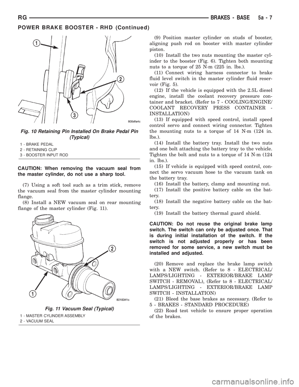
CAUTION: When removing the vacuum seal from
the master cylinder, do not use a sharp tool.
(7) Using a soft tool such as a trim stick, remove
the vacuum seal from the master cylinder mounting
flange.
(8) Install a NEW vacuum seal on rear mounting
flange of the master cylinder (Fig. 11).(9) Position master cylinder on studs of booster,
aligning push rod on booster with master cylinder
piston.
(10) Install the two nuts mounting the master cyl-
inder to the booster (Fig. 6). Tighten both mounting
nuts to a torque of 25 N´m (225 in. lbs.).
(11) Connect wiring harness connector to brake
fluid level switch in the master cylinder fluid reser-
voir (Fig. 5).
(12) If the vehicle is equipped with the 2.5L diesel
engine, install the coolant recovery pressure con-
tainer and bracket. (Refer to 7 - COOLING/ENGINE/
COOLANT RECOVERY PRESS CONTAINER -
INSTALLATION)
(13) If equipped with speed control, install speed
control servo and connect wiring connector. Tighten
the mounting nuts to a torque of 14 N´m (124 in.
lbs.).
(14) Install the battery tray. Install the two nuts
and one bolt attaching the battery tray to the vehicle.
Tighten the bolt and nuts to a torque of 14 N´m (124
in. lbs.).
(15) If vehicle is equipped with speed control, con-
nect the servo vacuum hose to the vacuum tank on
the battery tray.
(16) Install the battery, clamp and mounting nut.
(17) Install the positive battery cable on the bat-
tery.
(18) Install the negative battery cable on the bat-
tery.
(19) Install the battery thermal guard shield.
CAUTION: Do not reuse the original brake lamp
switch. The switch can only be adjusted once. That
is during initial installation of the switch. If the
switch is not adjusted properly or has been
removed for some service, a new switch must be
installed and adjusted.
(20) Remove and replace the brake lamp switch
with a NEW switch. (Refer to 8 - ELECTRICAL/
LAMPS/LIGHTING - EXTERIOR/BRAKE LAMP
SWITCH - REMOVAL), (Refer to 8 - ELECTRICAL/
LAMPS/LIGHTING - EXTERIOR/BRAKE LAMP
SWITCH - INSTALLATION)
(21) Bleed the base brakes as necessary. (Refer to
5 - BRAKES - STANDARD PROCEDURE)
(22) Road test vehicle to ensure proper operation
of the brakes.
Fig. 10 Retaining Pin Installed On Brake Pedal Pin
(Typical)
1 - BRAKE PEDAL
2 - RETAINING CLIP
3 - BOOSTER INPUT ROD
Fig. 11 Vacuum Seal (Typical)
1 - MASTER CYLINDER ASSEMBLY
2 - VACUUM SEAL
RGBRAKES - BASE5a-7
POWER BRAKE BOOSTER - RHD (Continued)
Page 1712 of 4284
ROTORS
SPECIFICATIONS
BRAKE ROTOR
NOTE: Use the following information on all 4 wheel
disc brake vehicles that are equipped with BR3
sales code.When refacing a rotor, the required TIR (Total
Indicator Reading) and thickness variation limits
MUST BE MAINTAINED. Extreme care in the oper-
ation of rotor turning equipment is required.
SPECIFICATIONS/LIMITS
Brake
RotorRotor ThicknessMinimum Rotor
ThicknessRotor
Thickness
VariationRotor Runout *Rotor Micro
Finish
Front27.9-28.1 mm
1.098 -1.106 in.26.5 mm
1.043 in0.010 mm
0.0004 in.0.030 mm
0.0012 in.15-80 RMS
Rear12.25-12.75 mm
0.482-0.502 in.11.25 mm
0.443 in.0.013 mm
0.0005 in.0.14 mm
0.0055 in.15-80 RMS
* TIR Total Indicator Reading (Measured On Vehicle)
PARKING BRAKE
DESCRIPTION
The parking brake system on this vehicle features
a hand-operated parking brake lever. The lever is
located between the two front seats and requires a
special front cable.
CABLES - PARKING BRAKE
REMOVAL - FRONT CABLE
(Refer to 5 - BRAKES - BASE/PARKING BRAKE/
LEVER - REMOVAL)
INSTALLATION - FRONT CABLE
(Refer to 5 - BRAKES - BASE/PARKING BRAKE/
LEVER - INSTALLATION)
LEVER - PARKING BRAKE
REMOVAL - PARKING BRAKE LEVER AND
FRONT CABLE
(1) Raise vehicle. (Refer to LUBRICATION &
MAINTENANCE/HOISTING - STANDARD PROCE-
DURE)
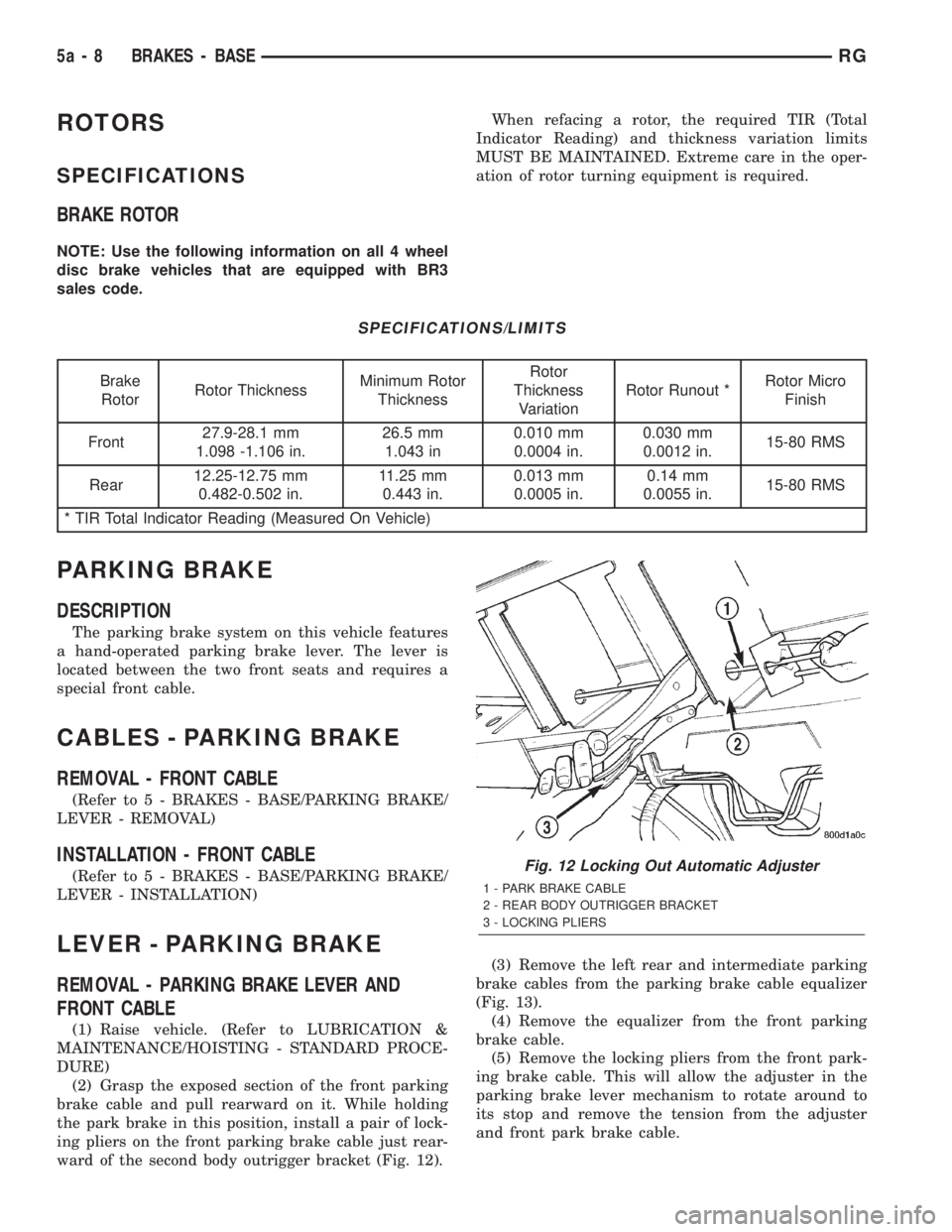
(2) Grasp the exposed section of the front parking
brake cable and pull rearward on it. While holding
the park brake in this position, install a pair of lock-
ing pliers on the front parking brake cable just rear-
ward of the second body outrigger bracket (Fig. 12).(3) Remove the left rear and intermediate parking
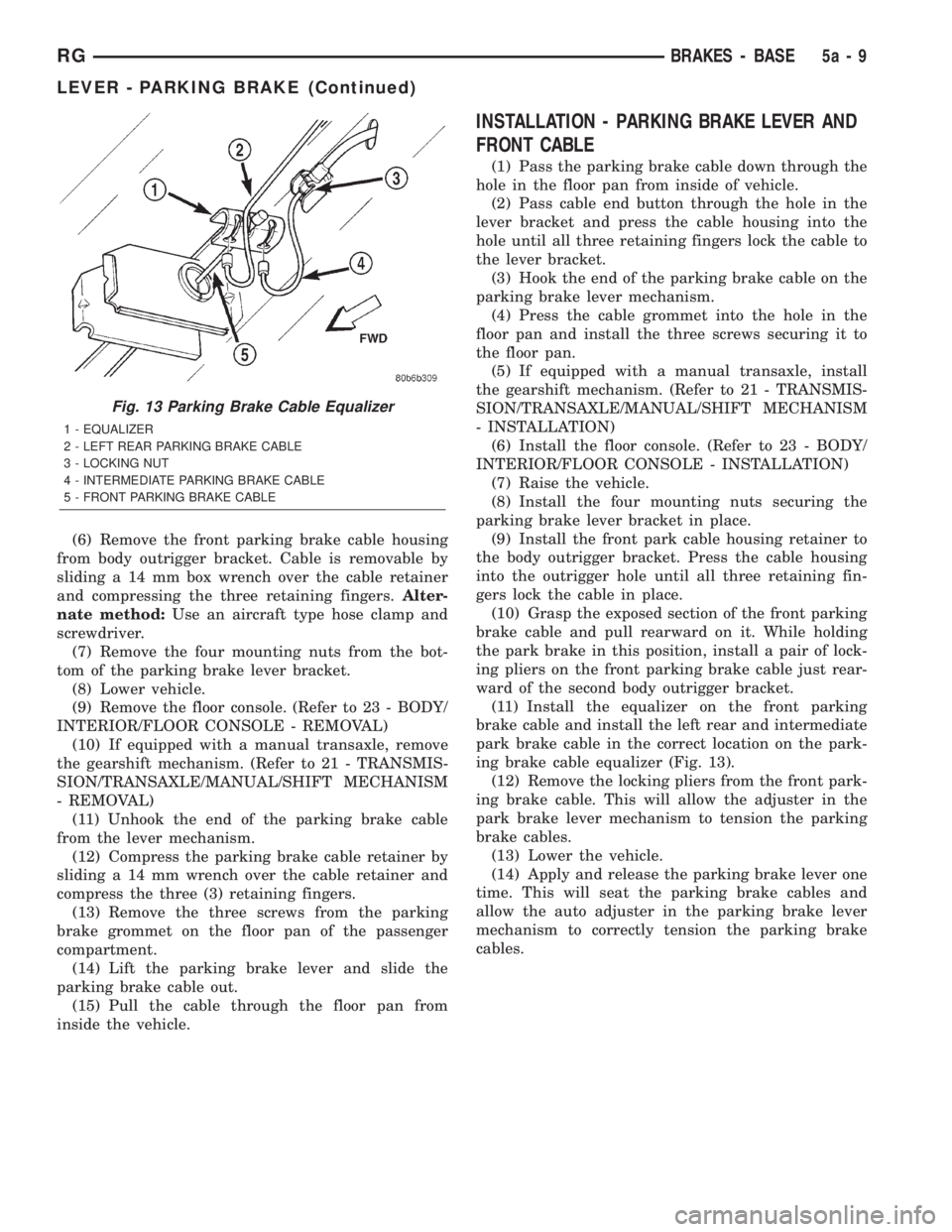
brake cables from the parking brake cable equalizer
(Fig. 13).
(4) Remove the equalizer from the front parking
brake cable.
(5) Remove the locking pliers from the front park-
ing brake cable. This will allow the adjuster in the
parking brake lever mechanism to rotate around to
its stop and remove the tension from the adjuster
and front park brake cable.
Fig. 12 Locking Out Automatic Adjuster
1 - PARK BRAKE CABLE
2 - REAR BODY OUTRIGGER BRACKET
3 - LOCKING PLIERS
5a - 8 BRAKES - BASERG
Page 1713 of 4284
(6) Remove the front parking brake cable housing
from body outrigger bracket. Cable is removable by
sliding a 14 mm box wrench over the cable retainer
and compressing the three retaining fingers.Alter-
nate method:Use an aircraft type hose clamp and
screwdriver.
(7) Remove the four mounting nuts from the bot-
tom of the parking brake lever bracket.
(8) Lower vehicle.
(9) Remove the floor console. (Refer to 23 - BODY/
INTERIOR/FLOOR CONSOLE - REMOVAL)
(10) If equipped with a manual transaxle, remove
the gearshift mechanism. (Refer to 21 - TRANSMIS-
SION/TRANSAXLE/MANUAL/SHIFT MECHANISM
- REMOVAL)
(11) Unhook the end of the parking brake cable
from the lever mechanism.
(12) Compress the parking brake cable retainer by
sliding a 14 mm wrench over the cable retainer and
compress the three (3) retaining fingers.
(13) Remove the three screws from the parking
brake grommet on the floor pan of the passenger
compartment.
(14) Lift the parking brake lever and slide the
parking brake cable out.
(15) Pull the cable through the floor pan from
inside the vehicle.
INSTALLATION - PARKING BRAKE LEVER AND
FRONT CABLE
(1) Pass the parking brake cable down through the
hole in the floor pan from inside of vehicle.
(2) Pass cable end button through the hole in the
lever bracket and press the cable housing into the
hole until all three retaining fingers lock the cable to
the lever bracket.
(3) Hook the end of the parking brake cable on the
parking brake lever mechanism.
(4) Press the cable grommet into the hole in the
floor pan and install the three screws securing it to
the floor pan.
(5) If equipped with a manual transaxle, install
the gearshift mechanism. (Refer to 21 - TRANSMIS-
SION/TRANSAXLE/MANUAL/SHIFT MECHANISM
- INSTALLATION)
(6) Install the floor console. (Refer to 23 - BODY/
INTERIOR/FLOOR CONSOLE - INSTALLATION)
(7) Raise the vehicle.
(8) Install the four mounting nuts securing the
parking brake lever bracket in place.
(9) Install the front park cable housing retainer to
the body outrigger bracket. Press the cable housing
into the outrigger hole until all three retaining fin-
gers lock the cable in place.
(10) Grasp the exposed section of the front parking
brake cable and pull rearward on it. While holding
the park brake in this position, install a pair of lock-
ing pliers on the front parking brake cable just rear-
ward of the second body outrigger bracket.
(11) Install the equalizer on the front parking
brake cable and install the left rear and intermediate
park brake cable in the correct location on the park-
ing brake cable equalizer (Fig. 13).
(12) Remove the locking pliers from the front park-
ing brake cable. This will allow the adjuster in the
park brake lever mechanism to tension the parking
brake cables.
(13) Lower the vehicle.
(14) Apply and release the parking brake lever one
time. This will seat the parking brake cables and
allow the auto adjuster in the parking brake lever
mechanism to correctly tension the parking brake
cables.
Fig. 13 Parking Brake Cable Equalizer
1 - EQUALIZER
2 - LEFT REAR PARKING BRAKE CABLE
3 - LOCKING NUT
4 - INTERMEDIATE PARKING BRAKE CABLE
5 - FRONT PARKING BRAKE CABLE
RGBRAKES - BASE5a-9
LEVER - PARKING BRAKE (Continued)
Page 1714 of 4284
BRAKES - ABS
TABLE OF CONTENTS
page page
BRAKES - ABS
DESCRIPTION...........................10
ICU (INTEGRATED CONTROL UNIT) - RHD
REMOVAL..............................10DISASSEMBLY...........................11
ASSEMBLY.............................12
INSTALLATION...........................13
BRAKES - ABS
DESCRIPTION - ANTILOCK BRAKE SYSTEM
Four-wheel disc antilock brakes are standard on all
models. The Mark 20e antilock brake system is used
on all models. Depending on whether the vehicle is a
left-hand drive (LHD) or right-hand drive (RHD)
model, the integrated control unit (ICU) is located in
one of two locations. On LHD models, the ICU is
mounted above the front suspension cradle/cross-
member below the master cylinder. On RHD models,
the ICU is located behind the front suspension cra-
dle/crossmember on the left side of the vehicle.
ICU (INTEGRATED CONTROL
UNIT) - RHD
REMOVAL - RHD
NOTE: Before proceeding, review all WARNINGS
AND CAUTIONS.
(1) Disconnect the negative (ground) cable from
the battery and isolate cable.
(2) Using a brake pedal depressor, move and lock
the brake pedal to a position past the first inch of
pedal travel.This will prevent brake fluid from
draining out of the master cylinder when the
brake tubes are removed from the HCU.
(3) Raise vehicle. See Hoisting in the Lubrication
And Maintenance.
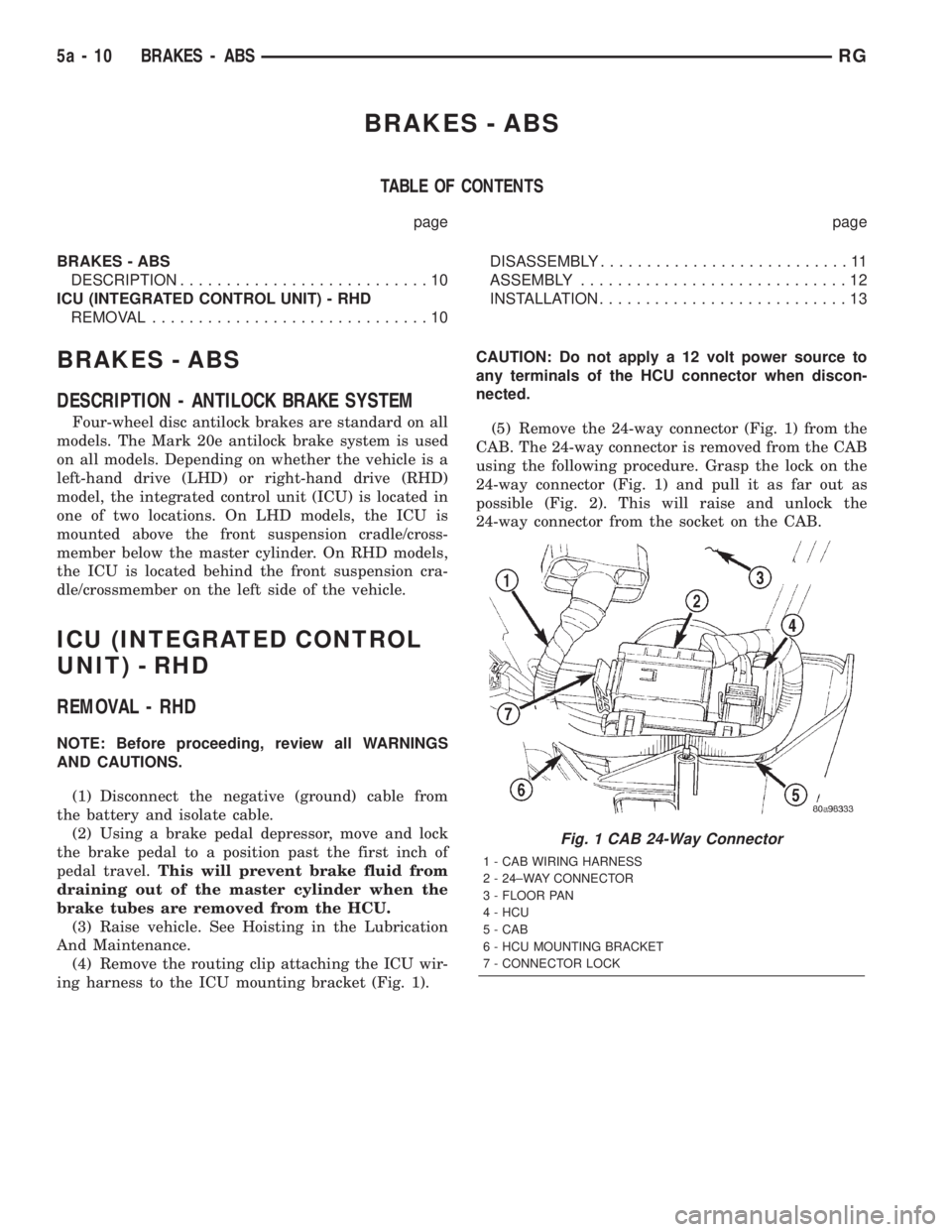
(4) Remove the routing clip attaching the ICU wir-
ing harness to the ICU mounting bracket (Fig. 1).CAUTION: Do not apply a 12 volt power source to
any terminals of the HCU connector when discon-
nected.
(5) Remove the 24-way connector (Fig. 1) from the
CAB. The 24-way connector is removed from the CAB
using the following procedure. Grasp the lock on the
24-way connector (Fig. 1) and pull it as far out as
possible (Fig. 2). This will raise and unlock the
24-way connector from the socket on the CAB.
Fig. 1 CAB 24-Way Connector
1 - CAB WIRING HARNESS
2 - 24±WAY CONNECTOR
3 - FLOOR PAN
4 - HCU
5 - CAB
6 - HCU MOUNTING BRACKET
7 - CONNECTOR LOCK
5a - 10 BRAKES - ABSRG
Page 1715 of 4284
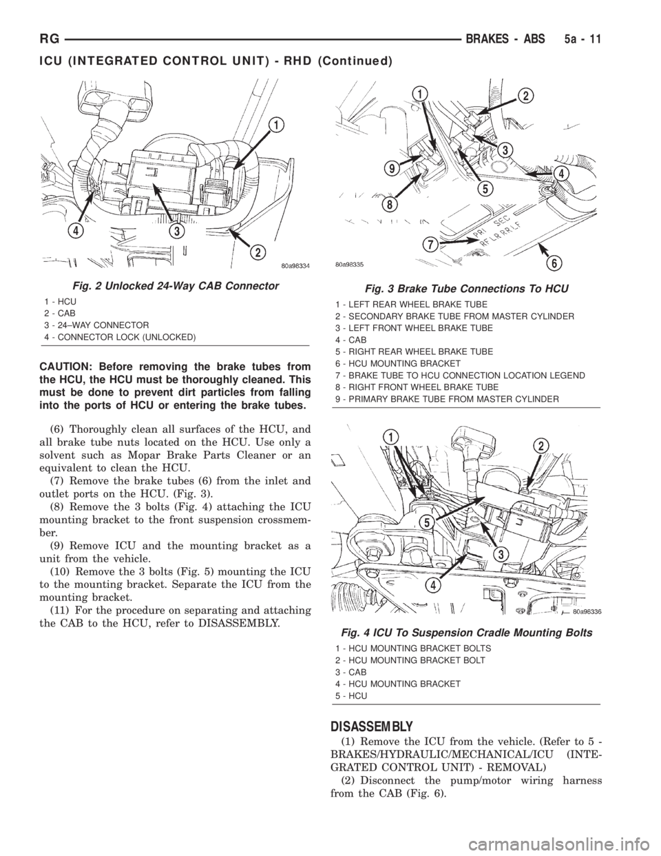
CAUTION: Before removing the brake tubes from
the HCU, the HCU must be thoroughly cleaned. This
must be done to prevent dirt particles from falling
into the ports of HCU or entering the brake tubes.
(6) Thoroughly clean all surfaces of the HCU, and
all brake tube nuts located on the HCU. Use only a
solvent such as Mopar Brake Parts Cleaner or an
equivalent to clean the HCU.
(7) Remove the brake tubes (6) from the inlet and
outlet ports on the HCU. (Fig. 3).
(8) Remove the 3 bolts (Fig. 4) attaching the ICU
mounting bracket to the front suspension crossmem-
ber.
(9) Remove ICU and the mounting bracket as a
unit from the vehicle.
(10) Remove the 3 bolts (Fig. 5) mounting the ICU
to the mounting bracket. Separate the ICU from the
mounting bracket.
(11) For the procedure on separating and attaching
the CAB to the HCU, refer to DISASSEMBLY.
DISASSEMBLY
(1) Remove the ICU from the vehicle. (Refer to 5 -
BRAKES/HYDRAULIC/MECHANICAL/ICU (INTE-
GRATED CONTROL UNIT) - REMOVAL)
(2) Disconnect the pump/motor wiring harness
from the CAB (Fig. 6).
Fig. 2 Unlocked 24-Way CAB Connector
1 - HCU
2 - CAB
3 - 24±WAY CONNECTOR
4 - CONNECTOR LOCK (UNLOCKED)
Fig. 3 Brake Tube Connections To HCU
1 - LEFT REAR WHEEL BRAKE TUBE
2 - SECONDARY BRAKE TUBE FROM MASTER CYLINDER
3 - LEFT FRONT WHEEL BRAKE TUBE
4 - CAB
5 - RIGHT REAR WHEEL BRAKE TUBE
6 - HCU MOUNTING BRACKET
7 - BRAKE TUBE TO HCU CONNECTION LOCATION LEGEND
8 - RIGHT FRONT WHEEL BRAKE TUBE
9 - PRIMARY BRAKE TUBE FROM MASTER CYLINDER
Fig. 4 ICU To Suspension Cradle Mounting Bolts
1 - HCU MOUNTING BRACKET BOLTS
2 - HCU MOUNTING BRACKET BOLT
3 - CAB
4 - HCU MOUNTING BRACKET
5 - HCU
RGBRAKES - ABS5a-11
ICU (INTEGRATED CONTROL UNIT) - RHD (Continued)
Page 1716 of 4284
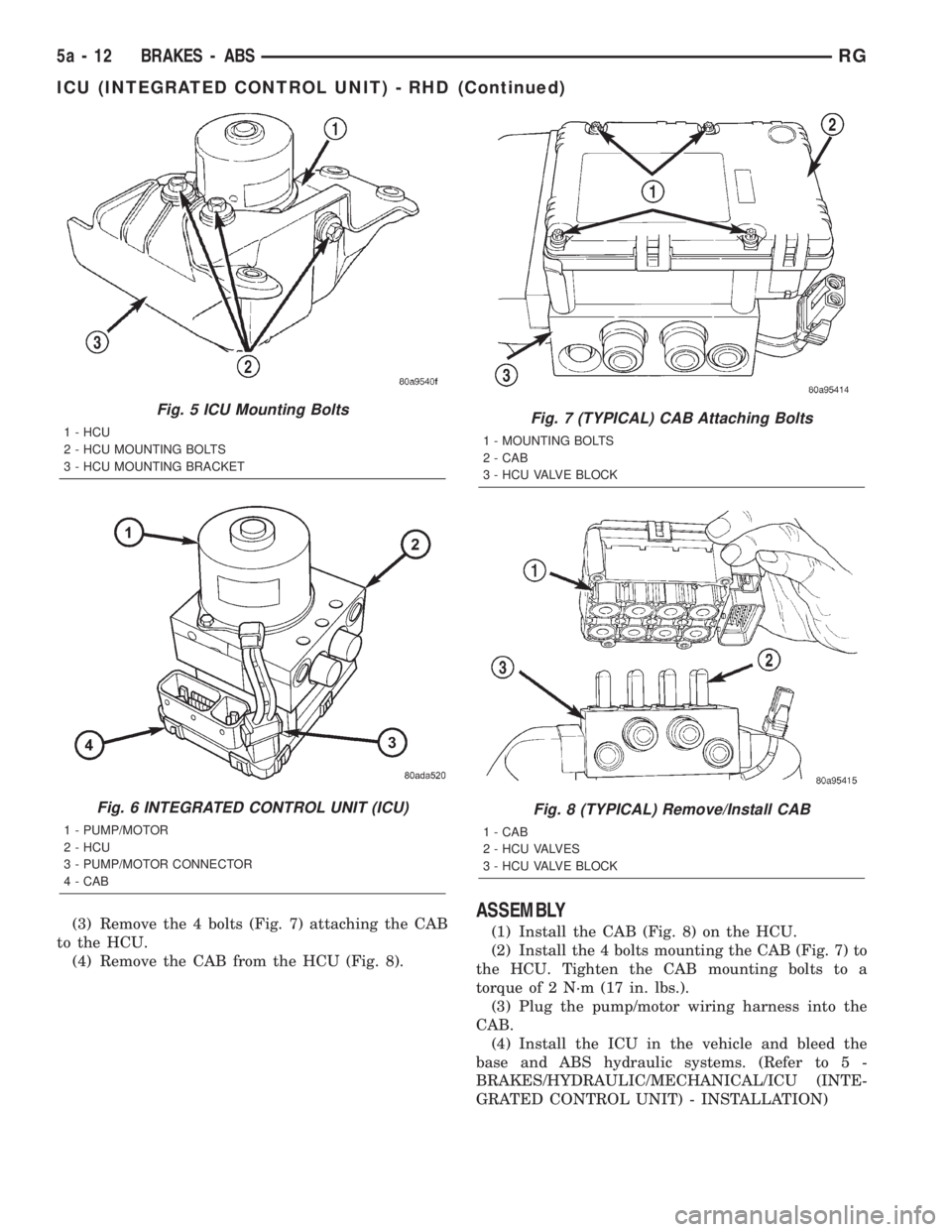
(3) Remove the 4 bolts (Fig. 7) attaching the CAB
to the HCU.
(4) Remove the CAB from the HCU (Fig. 8).ASSEMBLY
(1) Install the CAB (Fig. 8) on the HCU.
(2) Install the 4 bolts mounting the CAB (Fig. 7) to
the HCU. Tighten the CAB mounting bolts to a
torque of 2 N´m (17 in. lbs.).
(3) Plug the pump/motor wiring harness into the
CAB.
(4) Install the ICU in the vehicle and bleed the
base and ABS hydraulic systems. (Refer to 5 -
BRAKES/HYDRAULIC/MECHANICAL/ICU (INTE-
GRATED CONTROL UNIT) - INSTALLATION)
Fig. 5 ICU Mounting Bolts
1 - HCU
2 - HCU MOUNTING BOLTS
3 - HCU MOUNTING BRACKET
Fig. 6 INTEGRATED CONTROL UNIT (ICU)
1 - PUMP/MOTOR
2 - HCU
3 - PUMP/MOTOR CONNECTOR
4 - CAB
Fig. 7 (TYPICAL) CAB Attaching Bolts
1 - MOUNTING BOLTS
2 - CAB
3 - HCU VALVE BLOCK
Fig. 8 (TYPICAL) Remove/Install CAB
1 - CAB
2 - HCU VALVES
3 - HCU VALVE BLOCK
5a - 12 BRAKES - ABSRG
ICU (INTEGRATED CONTROL UNIT) - RHD (Continued)
Page 1717 of 4284
INSTALLATION - RHD
(1) Install the ICU on the mounting bracket (Fig.
5). Install the 3 bolts (Fig. 5) attaching the ICU to
the mounting bracket. Tighten the 3 mounting bolts
to a torque of 11 N´m (97 in. lbs.).
CAUTION: The ICU mounting bracket to front sus-
pension cradle mounting bolts have a unique corro-
sion protection coating and a special aluminum
washer. For this reason, only the original, or origi-
nal equipment Mopar replacement bolts can be
used to mount the ICU bracket to the front suspen-
sion crossmember.
(2) Install the ICU and its mounting bracket as an
assembly on the front suspension crossmember.
Install the 3 bolts attaching the ICU bracket to the
crossmember (Fig. 4). Tighten the 3 mounting bolts
to a torque of 28 N´m (250 in. lbs.).
CAUTION: Because of the flexible section in the pri-
mary and secondary brake tubes, and the brake
tubes between the HCU and the proportioning
valve, the brake tubes must be held in proper ori-
entation when tightened and torqued. These tubes
must not contact each other or other vehicle com-
ponents when installed. Also, after the brake tubes
are installed on the HCU, ensure all spacer clips are
reinstalled on the brake tubes.
CAUTION: When installing the chassis brake tubes
on the HCU valve block, they must be located cor-
rectly in the valve block to ensure proper ABS oper-
ation. Refer to (Fig. 3) for the correct chassis brake
tube locations.
NOTE: The chassis brake tube attachment locations
to the HCU, are marked on the bottom of the ICU
mounting bracket.
(3) Install the 6 chassis brake tubes into their cor-
rect port locations on the HCU valve block as shown
in (Fig. 3). Tighten the tube nuts to a torque of 17
N´m (145 in. lbs.).
NOTE: Before installing the 24-way connector in the
CAB be sure the seal is properly installed in the
connector.(4) Install the 24-way connector (Fig. 1) on the
CAB using the following procedure. Position the
24-way connector in the socket of the CAB and care-
fully push it down as far as possible. When connector
is fully seated by hand into the CAB socket, push in
the connector lock (Fig. 2). This will pull the connec-
tor into the socket of the CAB and lock it in the
installed position.
NOTE: The CAB wiring harness must be clipped to
the ICU mounting bracket. This will ensure the wir-
ing harness is properly routed and does not contact
the brake tubes or the body of the vehicle.
(5) Clip the cab wiring harness (Fig. 1) to the ICU
mounting bracket.
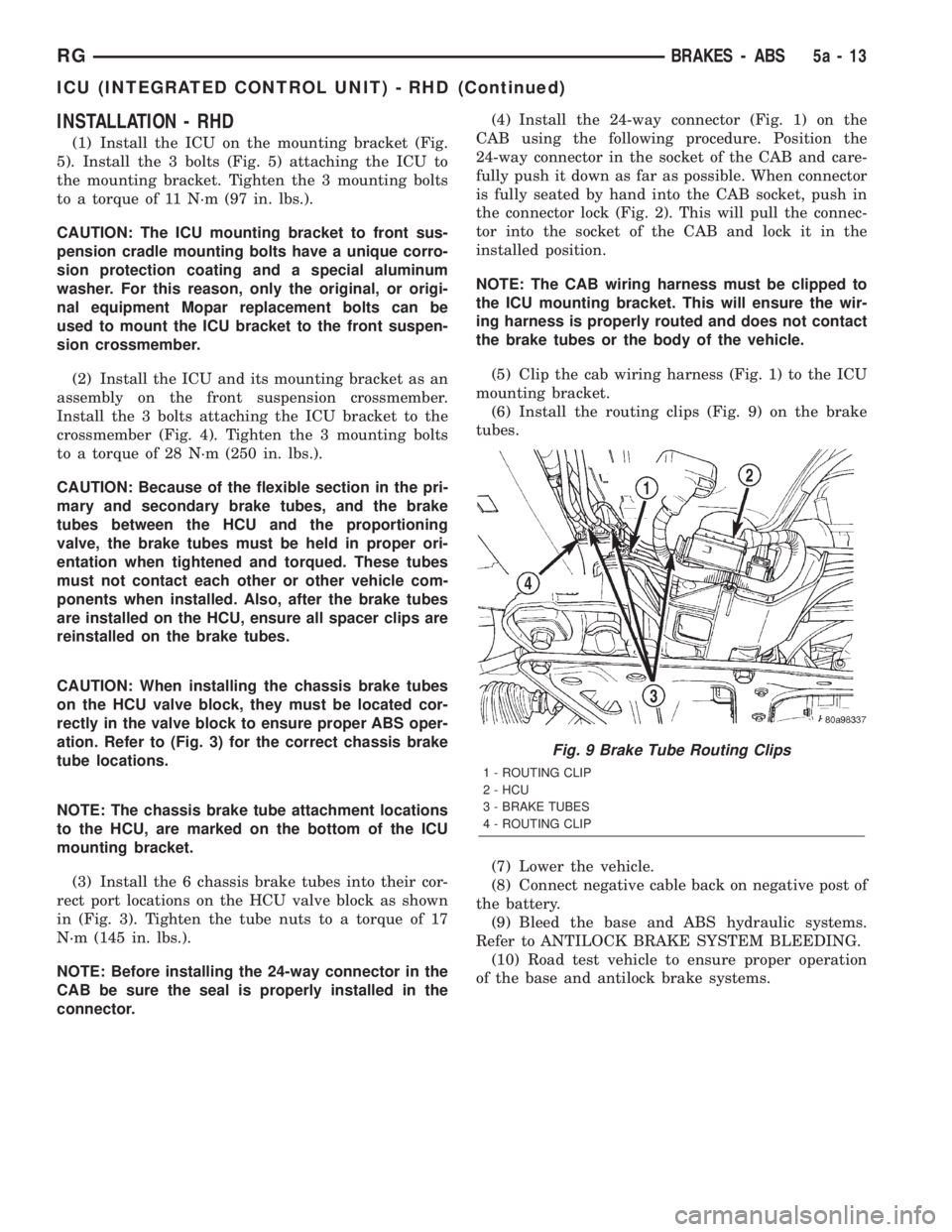
(6) Install the routing clips (Fig. 9) on the brake
tubes.
(7) Lower the vehicle.
(8) Connect negative cable back on negative post of
the battery.
(9) Bleed the base and ABS hydraulic systems.
Refer to ANTILOCK BRAKE SYSTEM BLEEDING.
(10) Road test vehicle to ensure proper operation
of the base and antilock brake systems.
Fig. 9 Brake Tube Routing Clips
1 - ROUTING CLIP
2 - HCU
3 - BRAKE TUBES
4 - ROUTING CLIP
RGBRAKES - ABS5a-13
ICU (INTEGRATED CONTROL UNIT) - RHD (Continued)
Page 1718 of 4284

Page 1719 of 4284
CLUTCH
TABLE OF CONTENTS
page page
CLUTCH
DESCRIPTION...........................1
DIAGNOSIS AND TESTING
DIAGNOSIS AND TESTING - CLUTCH
SYSTEM..............................4
DIAGNOSIS AND TESTING - DRIVE PLATE
MISALIGNMENT.........................7
DIAGNOSIS AND TESTING - CLUTCH
COVER AND DISC RUNOUT...............7
DIAGNOSIS AND TESTING - CLUTCH
CHATTER COMPLAINTS..................7
SPECIAL TOOLS..........................7
CLUTCH RELEASE CABLE - LHD
REMOVAL...............................7
INSTALLATION...........................9
CLUTCH RELEASE LEVER AND BEARING
REMOVAL..............................11INSTALLATION..........................12
MASTER CYLINDER - RHD
REMOVAL..............................13
INSTALLATION..........................14
MODULAR CLUTCH ASSY - 2.4L GAS
REMOVAL..............................14
INSTALLATION..........................15
SLAVE CYLINDER - RHD
REMOVAL..............................15
INSTALLATION..........................15
CLUTCH DISC AND PRESSURE PLATE - 2.5L
TD
REMOVAL..............................15
INSTALLATION..........................15
FLYWHEEL
REMOVAL..............................16
INSTALLATION..........................16
CLUTCH
DESCRIPTION
CLUTCH COMPONENTS
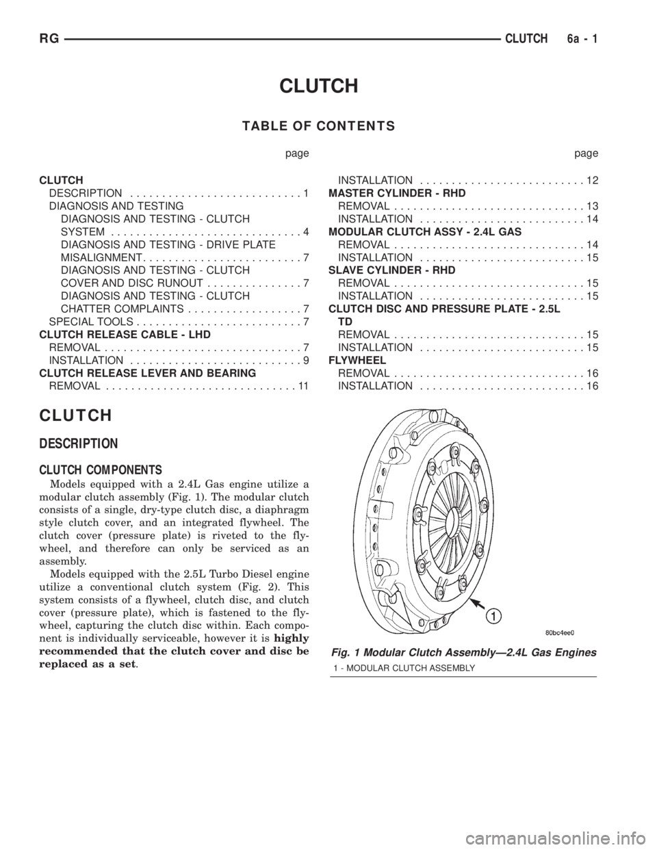
Models equipped with a 2.4L Gas engine utilize a
modular clutch assembly (Fig. 1). The modular clutch
consists of a single, dry-type clutch disc, a diaphragm
style clutch cover, and an integrated flywheel. The
clutch cover (pressure plate) is riveted to the fly-
wheel, and therefore can only be serviced as an
assembly.
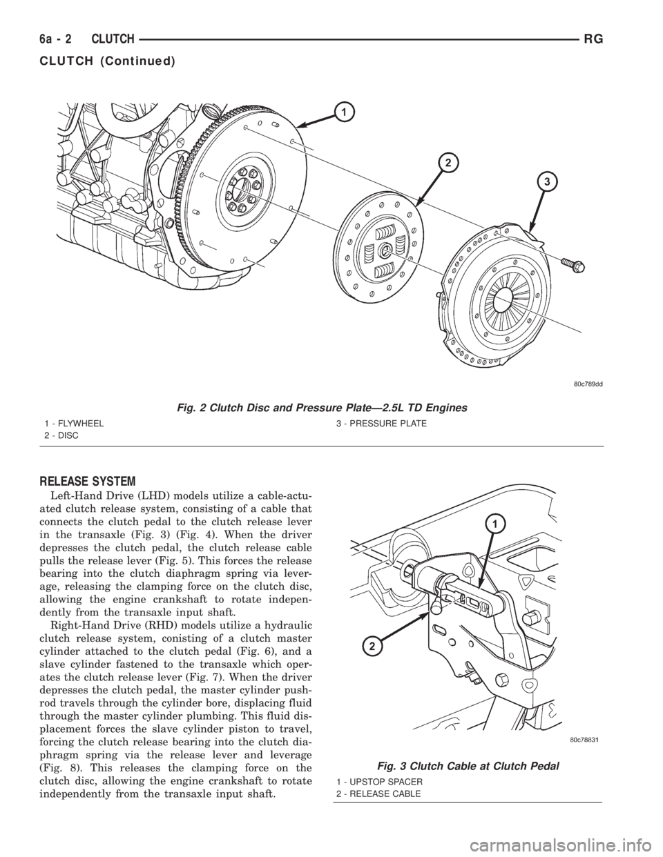
Models equipped with the 2.5L Turbo Diesel engine
utilize a conventional clutch system (Fig. 2). This
system consists of a flywheel, clutch disc, and clutch
cover (pressure plate), which is fastened to the fly-
wheel, capturing the clutch disc within. Each compo-
nent is individually serviceable, however it ishighly
recommended that the clutch cover and disc be
replaced as a set.
Fig. 1 Modular Clutch AssemblyÐ2.4L Gas Engines
1 - MODULAR CLUTCH ASSEMBLY
RGCLUTCH6a-1
Page 1720 of 4284
RELEASE SYSTEM
Left-Hand Drive (LHD) models utilize a cable-actu-
ated clutch release system, consisting of a cable that
connects the clutch pedal to the clutch release lever
in the transaxle (Fig. 3) (Fig. 4). When the driver
depresses the clutch pedal, the clutch release cable
pulls the release lever (Fig. 5). This forces the release
bearing into the clutch diaphragm spring via lever-
age, releasing the clamping force on the clutch disc,
allowing the engine crankshaft to rotate indepen-
dently from the transaxle input shaft.
Right-Hand Drive (RHD) models utilize a hydraulic
clutch release system, conisting of a clutch master
cylinder attached to the clutch pedal (Fig. 6), and a
slave cylinder fastened to the transaxle which oper-
ates the clutch release lever (Fig. 7). When the driver
depresses the clutch pedal, the master cylinder push-
rod travels through the cylinder bore, displacing fluid
through the master cylinder plumbing. This fluid dis-
placement forces the slave cylinder piston to travel,
forcing the clutch release bearing into the clutch dia-
phragm spring via the release lever and leverage
(Fig. 8). This releases the clamping force on the
clutch disc, allowing the engine crankshaft to rotate
independently from the transaxle input shaft.
Fig. 2 Clutch Disc and Pressure PlateÐ2.5L TD Engines
1 - FLYWHEEL
2 - DISC3 - PRESSURE PLATE
Fig. 3 Clutch Cable at Clutch Pedal
1 - UPSTOP SPACER
2 - RELEASE CABLE
6a - 2 CLUTCHRG
CLUTCH (Continued)