relay CHRYSLER VOYAGER 2001 Service Manual
[x] Cancel search | Manufacturer: CHRYSLER, Model Year: 2001, Model line: VOYAGER, Model: CHRYSLER VOYAGER 2001Pages: 4284, PDF Size: 83.53 MB
Page 4 of 4284
TABLE OF CONTENTS
1.0 INTRODUCTION.........................................................1
1.1SYSTEM COVERAGE...............................................1
1.2SIX-STEP TROUBLESHOOTING PROCEDURE..........................1
2.0 IDENTIFICATION OF SYSTEM.............................................1
3.0 SYSTEM DESCRIPTION AND FUNCTIONAL OPERATION......................1
3.1AIRBAG SYSTEM/OCCUPANT RESTRAINT CONTROLLER SYSTEM........2
3.1.1DRIVER AIRBAG...........................................3
3.1.2CLOCKSPRING............................................4
3.1.3PASSENGER AIRBAG......................................4
3.1.4SEAT BELT TENSIONER (SBT)...............................5
3.1.5SEAT BELT SWITCHES (SBS)................................5
3.1.6SIDE IMPACT AIRBAG CONTROL MODULE (SIACM)............5
3.1.7SEAT AIRBAGS (SAB)......................................6
3.1.8ORC/SIACM DIAGNOSTIC TROUBLE CODES..................6
3.1.9ACTIVE CODES...........................................7
3.1.10STORED CODES..........................................7
3.2AUDIO SYSTEM....................................................7
3.2.1REMOTE RADIO CONTROLS................................8
3.2.2CD CHANGER.............................................8
3.3BODY CONTROL MODULE...........................................8
3.4CHIME WARNING SYSTEM...........................................9
3.4.1CHIME PRIORITY..........................................9
3.4.2CHIME ON CONDITIONS....................................9
3.4.3WARNING LAMP ANNOUNCEMENT.........................10
3.4.4OTHER CHIME ON CONDITIONS............................10
3.5COMMUNICATION.................................................11
3.6DOOR AJAR SYSTEM..............................................12
3.7EXTERIOR LIGHTING SYSTEM......................................12
3.7.1HEADLAMP POWER......................................12
3.7.2HEADLAMP SWITCH......................................12
3.7.3PARK LAMP RELAY.......................................12
3.7.4FOG LAMP RELAY........................................12
3.7.5FOG LAMPS.............................................12
3.7.6EXTERIOR LIGHTING BATTERY SAVER......................13
3.7.7AUTO HEADLAMPS.......................................13
3.8FRONT CONTROL MODULE.........................................13
3.8.1CONTROLLED POWER FEEDS.............................13
3.8.2RELAY CONTROLS.......................................14
3.8.3ELECTRICAL INPUTS.....................................15
3.9HEATING & A/C...................................................16
3.9.1AUTOMATIC TEMPERATURE CONTROL (ATC)................16
3.9.1.1CABIN HEATER..........................................16
3.9.1.2SYSTEM OPERATION.....................................16
3.9.1.3BLOWER MOTOR OPERATION.............................16
3.9.1.4INFRARED SENSORS.....................................16
3.9.1.5REAR ATC SWITCH.......................................16
3.9.1.6COOLDOWN TESTING....................................16
3.9.1.7ACTIVE AND STORED TROUBLE CODES....................17
3.9.2MANUAL TEMPERATURE CONTROL.........................17
i
Page 5 of 4284
TABLE OF CONTENTS - Continued
3.9.2.1SYSTEM AVAILABILITY....................................17
3.9.2.2CABIN HEATER..........................................17
3.9.2.3ZONE CONTROL ± SINGLE-ZONE...........................17
3.9.2.4ZONE CONTROL ± DUAL-ZONE.............................17
3.9.2.5AIR DISTRIBUTION.......................................17
3.9.2.6DOOR ACTUATORS.......................................17
3.9.2.7DOOR ACTUATOR CONTROL..............................17
3.9.2.8HVAC SYSTEM RELAYS...................................18
3.9.2.9EVAPORATOR TEMPERATURE SENSOR.....................18
3.9.2.10A/C ± HEATER CONTROL MODULE, SWITCH OPERATION......18
3.9.2.11HVAC DIAGNOSTICS.....................................19
3.10CABIN HEATER...................................................19
3.10.1GENERAL SAFETY INFORMATION..........................19
3.10.2COMPONENT DESCRIPTION AND OPERATION...............19
3.10.2.1DCHA ASSEMBLY.........................................19
3.10.2.2COMBUSTION AIR FAN...................................20
3.10.2.3BURNER HOUSING.......................................20
3.10.2.4BURNER INSERT.........................................20
3.10.2.5CONTROL UNIT/HEAT EXCHANGER.........................20
3.10.2.6DOSING PUMP...........................................20
3.10.3OPERATION.............................................20
3.10.3.1ACTIVATION.............................................20
3.10.3.2HEATING................................................21
3.10.3.3DEACTIVATION...........................................21
3.10.4DIAGNOSTICS...........................................21
3.11INSTRUMENT CLUSTER............................................21
3.11.1INSTRUMENT CLUSTER SELF TEST........................22
3.11.2MESSAGE CENTER.......................................22
3.12INTERIOR LIGHTING...............................................22
3.12.1COURTESY LAMP CONTROL...............................22
3.12.2ILLUMINATED ENTRY.....................................22
3.12.3INTERIOR LIGHTING BATTERY SAVER......................22
3.13MEMORY SYSTEM.................................................22
3.13.1POWER SEAT............................................22
3.13.2MEMORY MIRRORS.......................................23
3.14OVERHEAD CONSOLE.............................................23
3.14.1COMPASS/MINI-TRIP COMPUTER (CMTC)....................23
3.14.2ELECTRONIC VEHICLE INFORMATION CENTER (EVIC)........23
3.14.3SETTING THE COMPASS..................................23
3.14.4SETTING THE VARIANCE..................................23
3.15POWER DOOR LOCK SYSTEM......................................24
3.15.1SLIDING DOOR MEMORY LOCK............................24
3.15.2DOOR LOCK INHIBIT......................................24
3.15.3AUTOMATIC DOOR LOCKS................................24
3.15.4REMOTE KEYLESS ENTRY (RKE)...........................24
3.16POWER FOLDING MIRRORS........................................24
3.17POWER LIFTGATE SYSTEM.........................................25
3.17.1POWER LIFTGATE........................................25
3.17.2DIAGNOSTIC FEATURES..................................25
3.17.3SYSTEM INHIBITORS.....................................25
3.18POWER SLIDING DOOR SYSTEM....................................25
3.18.1POWER SLIDING DOOR...................................25
3.18.2DIAGNOSTIC FEATURES..................................26
ii
Page 14 of 4284
TABLE OF CONTENTS - Continued
*BUS +/- SIGNALS OPEN OR NO RESPONSE FROM INSTRUMENT CLUSTER . .383
*BUS +/- SIGNALS OPEN OR NO RESPONSE FROM LEFT SLIDING DOOR
CONTROL MODULE....................................................386
*BUS +/- SIGNALS OPEN OR NO RESPONSE FROM POWER LIFTGATE
MODULE.............................................................389
*BUS +/- SIGNALS OPEN OR NO RESPONSE FROM RIGHT SLIDING DOOR
CONTROL MODULE....................................................392
*BUS +/- SIGNALS OPEN OR NO RESPONSE FROM THATCHAM ALARM
MODULE.............................................................395
*NO RESPONSE FROM CABIN HEATER ASSIST - DIESEL ONLY..............397
*NO RESPONSE FROM CONTROLLER ANTILOCK BRAKE...................399
*NO RESPONSE FROM ECM (PCI BUS) - DIESEL ONLY.....................401
*NO RESPONSE FROM ECM (SCI ONLY) - DIESEL ONLY....................402
*NO RESPONSE FROM FRONT CONTROL MODULE........................404
*NO RESPONSE FROM LEFT SIACM.....................................406
*NO RESPONSE FROM ORC............................................408
*NO RESPONSE FROM OVERHEAD CONSOLE............................410
*NO RESPONSE FROM PCM (PCI BUS)...................................412
*NO RESPONSE FROM PCM (SCI ONLY)..................................413
*NO RESPONSE FROM RADIO..........................................416
*NO RESPONSE FROM RIGHT SIACM....................................418
*NO RESPONSE FROM TRANSMISSION CONTROL MODULE................420
*PCI BUS COMMUNICATION FAILURE....................................423
DOOR AJAR
*HOOD AJAR CIRCUIT OPEN............................................426
*HOOD AJAR CIRCUIT SHORTED TO GROUND............................427
*LEFT FRONT DOOR AJAR SWITCH SENSE CIRCUIT OPEN.................428
*LEFT FRONT DOOR AJAR SWITCH SENSE CIRCUIT SHORTED TO GROUND. .429
*LEFT SLIDING DOOR AJAR SWITCH SENSE CIRCUIT OPEN................430
*LEFT SLIDING DOOR AJAR SWITCH SENSE CIRCUIT SHORTED TO
GROUND.............................................................432
*LIFTGATE AJAR CIRCUIT OPEN.........................................433
*LIFTGATE AJAR CIRCUIT SHORTED TO GROUND.........................434
*RIGHT FRONT DOOR AJAR SWITCH SENSE CIRCUIT OPEN................435
*RIGHT FRONT DOOR AJAR SWITCH SENSE CIRCUIT SHORTED TO
GROUND.............................................................436
*RIGHT SLIDING DOOR AJAR CIRCUIT OPEN.............................437
*RIGHT SLIDING DOOR AJAR CIRCUIT SHORTED TO GROUND..............439
ELECTRICALLY HEATED SYSTEMS
EBL RUN ONLY RELAY OPEN...........................................440
EBL RUN ONLY RELAY SHORTED TO BATTERY............................442
EXTERIOR LIGHTING
BACKUP LAMP OUTPUT OPEN..........................................443
BACKUP LAMP OUTPUT SHORT.........................................445
FRONT FOG LAMP RELAY OPEN........................................446
FRONT FOG LAMP SHORTED TO BATTERY...............................448
HEADLAMP SWITCH MISMATCH.........................................449
HEADLAMP SWITCH OPEN.............................................450
HEADLAMP SWITCH SHORT TO GROUND................................452
HIGH BEAM SWITCH INPUT OPEN.......................................454
xi
Page 20 of 4284
TABLE OF CONTENTS - Continued
INCOMPLETE LATCH CINCH - OVERCURRENT............................841
INCOMPLETE LATCH CINCH - PAWL SWITCH FAILURE.....................843
INCOMPLETE LATCH CINCH - RATCHET SWITCH FAILURE..................845
INCOMPLETE LATCH RELEASE - FULL OPEN SWITCH FAILURE.............848
INCOMPLETE LATCH RELEASE - NO CURRENT...........................851
INCOMPLETE LATCH RELEASE - RATCHET SWITCH FAILURE...............853
INCOMPLETE LATCH RELEASE- NO REVERSE TO UNLOAD CLUTCH.........855
INCOMPLETE LATCH RELEASE- OVERCURRENT..........................856
INCOMPLETE LATCH RELEASE- PAWL SWITCH FAILURE...................857
INCOMPLETE LATCH RELEASE- SECTOR GEAR RETURN FAILURE..........859
INCOMPLETE POWER CLOSE - FULL OPEN SWITCH FAILURE...............860
INCOMPLETE POWER CLOSE - LATCH FAILURE...........................862
INCOMPLETE POWER CLOSE - MISSING HALL SIGNAL.....................868
INCOMPLETE POWER CLOSE - OVERCURRENT...........................871
INCOMPLETE POWER CLOSE - TIME OUT................................873
INCOMPLETE POWER OPEN - FULL OPEN SWITCH FAILURE................874
INCOMPLETE POWER OPEN - LATCH FAILURE............................876
INCOMPLETE POWER OPEN - MISSING HALL SIGNAL......................881
INCOMPLETE POWER OPEN - OVERCURRENT............................884
INCOMPLETE POWER OPEN - TIME OUT.................................886
IOD WAKE UPOPEN - PSD .............................................887
IOD WAKE UP PSD & PLG SHORT.......................................889
LEFT B-PILLAR SWITCH INPUT OPEN....................................891
LEFT B-PILLAR SWITCH INPUT SHORT...................................893
LEFT B-PILLAR SWITCH INPUT STUCK...................................894
LOOPBACK TEST FAILURE.............................................895
LOSS OF BCM MESSAGES.............................................896
LOSS OF EATX MESSAGES.............................................897
LOSS OF FCM MESSAGES.............................................898
LOSS OF SBEC MESSAGES............................................899
OVERHEAD LEFT SWITCH INPUT STUCK.................................900
OVERHEAD RIGHT SWITCH INPUT STUCK................................901
OVERHEAD RIGHT/LEFT SWITCHES SHORT..............................902
RIGHT B-PILLAR SWITCH INPUT OPEN...................................903
RIGHT B-PILLAR SWITCH INPUT SHORT..................................905
RIGHT B-PILLAR SWITCH INPUT STUCK..................................906
*POWER SLIDING DOOR INOPERATIVE..................................907
POWER MIRROR ± FOLDING
FOLD MIRROR OUTPUT FAILURE........................................908
PASSENGER MIRROR RELAY OUTPUT OPEN.............................910
PASSENGER MIRROR RELAY OUTPUT SHORT............................912
UNFOLD MIRROR OUTPUT FAILURE.....................................913
*BOTH MIRRORS DO NOT UNFOLD EXCEPT WITH EITHER FRONT DOOR. . . .916
*BOTH POWER FOLDING MIRRORS DO NOT FOLD........................917
*DRIVER FOLDING MIRROR DOES NOT FOLD.............................918
*PASSENGER FOLDING MIRROR DOES NOT FOLD........................920
VEHICLE THEFT/SECURITY
BCM MESSAGES NOT RECEIVED........................................922
HORN INPUT STUCK...................................................923
HORN RELAY OPEN...................................................924
HORN RELAY SHORTED TO BATTERY....................................925
xvii
Page 21 of 4284

TABLE OF CONTENTS - Continued
INTERNAL EEPROM WRITE ERROR......................................927
INTERNAL TRANSMIT FAILURE..........................................928
INTERNAL ULTRASONIC FAULT.........................................929
LOOPBACK ERROR....................................................935
NO VALID MESSAGES RECEIVED........................................936
PCI BUS SHORTED TO BATTERY........................................937
PCI BUS SHORTED TO GROUND........................................938
PCM MESSAGES NOT RECEIVED........................................939
VEHICLE THEFT ALARM INDICATOR OUTPUT OPEN.......................940
VEHICLE THEFT ALARM INDICATOR OUTPUT SHORT......................941
*ALARM TRIPS ON ITS OWN............................................942
*HOOD DOES NOT TRIP VTSS..........................................943
*LEFT FRONT DOOR DOES NOT TRIP VTSS..............................944
*LEFT SLIDING DOOR DOES NOT TRIP VTSS.............................945
*LIFTGATE DOES NOT TRIP VTSS.......................................946
*REPEATER LAMPS INOPERATIVE WITH ALARM...........................947
*RIGHT FRONT DOOR DOES NOT TRIP VTSS.............................948
*RIGHT SLIDING DOOR DOES NOT TRIP VTSS............................949
*VTSS INDICATOR INOPERATIVE........................................950
*VTSS INDICATOR LAMP INOPERATIVE...................................951
*VTSS SIREN INOP....................................................952
*VTSS WILL NOT ARM..................................................955
WINDSHIELD WIPER & WASHER
FR WIPER HI-LO RELAY OPEN..........................................956
FR WIPER HI-LO RELAY SHORT TO BATT.................................958
FRONT WASH SWITCH INPUT STUCK....................................959
FRONT WASHER OUTPUT OPEN........................................961
FRONT WIPER NOT PARKED............................................963
FRONT WIPER ON RELAY OPEN........................................965
FRONT WIPER ON RELAY SHORT TO BATT...............................966
FRONT WIPER PARK SWITCH SHORT TO GND............................967
FRONT WIPER SWITCH MUX INPUT OPEN................................969
FRONT WIPER SWITCH MUX INPUT SHORT TO GROUND...................971
HEADLAMP WASHER RELAY OPEN......................................973
HEADLAMP WASHER RELAY SHORT TO BATT.............................975
REAR WASH SWITCH INPUT STUCK.....................................976
REAR WASHER OUTPUT OPEN.........................................978
REAR WIPER OUTPUT OPEN...........................................980
REAR WIPER OUTPUT SHORT TO GROUND..............................982
REAR WIPER SWITCH MUX INPUT OPEN.................................984
REAR WIPER SWITCH MUX INPUT SHORT TO GROUND....................986
VERIFICATION TESTS
VERIFICATION TESTS..................................................988
8.0 COMPONENT LOCATIONS..............................................995
8.1AIRBAG SYSTEM.................................................995
8.2BODY CONTROL MODULE.........................................996
8.3ENGINE CONTROL MODULE.......................................996
8.4HEATING & A/C...................................................996
8.4.1ACTUATORS ± FRONT LHD...............................996
xviii
Page 25 of 4284
TABLE OF CONTENTS - Continued
LEFT REMOTE RADIO SWITCH - BLACK 2 WAY...........................1053
LEFT SEAT AIRBAG - YELLOW 2 WAY...................................1053
LEFT SIDE IMPACT AIRBAG CONTROL MODULE - YELLOW/RED 7 WAY......1053
LEFT SLIDING DOOR CONTROL MODULE C1 (POWER SLIDING DOOR) -
BLACK 8 WAY........................................................1053
LEFT SLIDING DOOR CONTROL MODULE C2 (POWER SLIDING DOOR) -
BLACK/RED 20 WAY..................................................1054
LEFT SLIDING DOOR LATCH SENSING SWITCH (POWER SLIDING DOOR) -
BLACK 6 WAY........................................................1054
LEFT SLIDING DOOR LOCK MOTOR (POWER SLIDING DOOR) - BLACK 4
WAY................................................................1054
LEFT SLIDING DOOR LOCK MOTOR/AJAR SWITCH (MANUAL
SLIDING DOOR) - BLACK 4 WAY........................................1055
LEFT SLIDING DOOR MOTOR (POWER SLIDING DOOR) - BLACK 8 WAY.....1055
LEFT STOP/TURN SIGNAL RELAY (TRAILER TOW) - BLACK 5 WAY..........1055
LEFT VISOR/VANITY LAMP (PREMIUM/LUXURY) - BLACK 2 WAY............1055
LICENSE LAMP (POWER LIFTGATE) - DK. GRAY 8 WAY....................1056
LICENSE LAMP (POWER RELEASE) - DK. GRAY 4 WAY....................1056
LIFTGATE AJAR SWITCH (MANUAL RELEASE) - BLACK 2 WAY..............1056
LIFTGATE AJAR SWITCH (POWER RELEASE) - BLACK 4 WAY..............1056
LIFTGATE CINCH/RELEASE MOTOR (POWER LIFTGATE) - BLUE 7 WAY......1057
LIFTGATE CYLINDER LOCK SWITCH - BLACK 2 WAY......................1057
LIFTGATE LEFT PINCH SENSOR (POWER LIFTGATE) - BLACK 2 WAY........1057
LIFTGATE RIGHT PINCH SENSOR (POWER LIFTGATE) - BLACK 2 WAY......1057
MEMORY POWER SEAT SWITCH - GREEN 10 WAY........................1058
MEMORY SEAT FRONT VERTICAL MOTOR - RED 2 WAY...................1058
MEMORY SEAT FRONT VERTICAL POSITION SENSOR - BLACK 3 WAY......1058
MEMORY SEAT HORIZONTAL MOTOR - BLACK 2 WAY.....................1058
MEMORY SEAT HORIZONTAL POSITION SENSOR - BLACK 3 WAY...........1058
MEMORY SEAT REAR VERTICAL MOTOR - RED 2 WAY....................1059
MEMORY SEAT REAR VERTICAL POSITION SENSOR - BLACK 3 WAY........1059
MEMORY SEAT RECLINER MOTOR - GREEN 2 WAY.......................1059
MEMORY SEAT RECLINER POSITION SENSOR - BLACK 3 WAY.............1059
MEMORY SEAT SWITCH - BLACK 2 WAY.................................1059
MEMORY SEAT/MIRROR MODULE C1 - GRAY 2 WAY......................1060
MEMORY SEAT/MIRROR MODULE C2 - GRAY 26 WAY.....................1060
MEMORY SEAT/MIRROR MODULE C3 - GRAY 16 WAY.....................1060
MEMORY SEAT/MIRROR MODULE C4 - WHITE 12 WAY....................1061
MODE DOOR ACTUATOR (ATC) - GRAY 2 WAY...........................1061
MODE DOOR ACTUATOR (MTC) - GRAY 2 WAY...........................1061
MULTI-FUNCTION SWITCH - BLACK 4 WAY...............................1061
OCCUPANT RESTRAINT CONTROLLER - YELLOW/RED 23 WAY.............1062
OVERHEAD CONSOLE (EXCEPT BASE) - BLACK 12 WAY..................1062
PASSENGER AIRBAG - YELLOW 4 WAY..................................1063
PASSENGER BLEND DOOR ACTUATOR (ATC) - GRAY 2 WAY...............1063
PASSENGER BLEND DOOR ACTUATOR (MTC) - GRAY 2 WAY...............1063
PASSENGER DOOR LOCK SWITCH - BLACK 3 WAY.......................1063
PASSENGER FOLDING MIRROR RELAY (BUILT-UP-EXPORT) - BLUE 9 WAY . .1064
PASSENGER SEAT BELT SWITCH-2WAY...............................1064
PASSENGER SEAT BELT TENSIONER-2WAY............................1064
FUSES (IPM).........................................................1066
ACCESSORY RELAY..................................................1066
DEFOGGER RELAY...................................................1066
xxii
Page 26 of 4284
TABLE OF CONTENTS - Continued
FRONT BLOWER MOTOR RELAY.......................................1066
FRONT CONTROL MODULE - BLACK 49 WAY.............................1067
FRONT FOG LAMP RELAY.............................................1068
HEADLAMP WASHER RELAY (BUILT-UP-EXPORT).........................1068
NAME BRAND SPEAKER RELAY........................................1068
PARK LAMP RELAY...................................................1068
POSITIVE TEMPERATURE COEFFICIENTS...............................1068
REAR BLOWER MOTOR RELAY........................................1068
POWER FOLDING MIRROR SWITCH (BUILT-UP-EXPORT) - BLACK 2 WAY. . . .1069
POWER LIFTGATE MODULE C1 - BLACK 8 WAY..........................1069
POWER LIFTGATE MODULE C2 - BLACK/RED 20 WAY.....................1069
POWER LIFTGATE MOTOR - BLACK 10 WAY.............................1070
POWER SEAT CIRCUIT BREAKER (30A) - GRAY 2 WAY....................1070
POWERTRAIN CONTROL MODULE C1 (2.4L/3.3L/3.8L) - GRAY/BLACK
40-WAY.............................................................1071
POWERTRAIN CONTROL MODULE C2 (2.4L/3.3L/3.8L) - GRAY/GRAY 40 WAY .1072
RADIO C1 - GRAY 7 WAY..............................................1073
RADIO C2 - BLACK 7 WAY.............................................1073
RADIO C3 - WHITE/RED 2 WAY.........................................1073
RADIO C4-8WAY....................................................1074
RADIO CHOKE - LT. GRAY 2 WAY.......................................1074
REAR A/C-HEATER UNIT (3 ZONE HVAC) - LT. GREEN 10 WAY..............1074
REAR AUTO TEMP CONTROL SWITCH (ATC) - BLACK 13 WAY..............1075
REAR BLOWER MOTOR POWER MODULE C1 (ATC) - RED/BLACK 4 WAY. . . .1075
REAR BLOWER MOTOR POWER MODULE C2 (ATC) - BLACK 2 WAY.........1075
REAR DOME LAMP (EXCEPT LUXURY) - GRAY 3 WAY.....................1075
REAR MODE MOTOR (ATC) - GRAY 2 WAY...............................1076
REAR TEMPERATURE MOTOR (ATC) - GRAY 2 WAY.......................1076
RECIRCULATION DOOR ACTUATOR (ATC) - GRAY 2 WAY..................1076
RECIRCULATION DOOR ACTUATOR (MTC) - GRAY 2 WAY..................1076
REMOTE KEYLESS ENTRY ANTENNA (JAPAN) - BLACK 2 WAY..............1077
REMOTE KEYLESS ENTRY MODULE - BLACK/RED 6 WAY.................1077
RIGHT B-PILLAR SWITCH - GRAY 3 WAY.................................1077
RIGHT CINCH/RELEASE MOTOR (POWER SLIDING DOOR) - GRAY 4 WAY. . . .1077
RIGHT CYLINDER LOCK SWITCH - BLACK 2 WAY.........................1078
RIGHT DOOR SPEAKER - BLACK/RED 6 WAY............................1078
RIGHT FOG LAMP - WHITE 2 WAY......................................1078
RIGHT FRONT DOOR LOCK MOTOR/AJAR SWITCH (EXCEPT BASE) -
BLACK 4 WAY........................................................1078
RIGHT FRONT PARK/TURN SIGNAL LAMP (EXCEPT BUILT-UP-EXPORT) -
BLACK 3 WAY........................................................1079
RIGHT FULL OPEN SWITCH (POWER SLIDING DOOR) - BLACK 2 WAY.......1079
RIGHT HEADLAMP (EXCEPT BUILT-UP-EXPORT) - BLACK 3 WAY............1079
RIGHT HIGH BEAM LAMP (BUILT-UP-EXPORT) - BLACK 2 WAY..............1079
RIGHT INSTRUMENT PANEL SPEAKER - BLACK 2 WAY....................1080
RIGHT LOW BEAM LAMP (BUILT-UP-EXPORT) - BLACK 2 WAY..............1080
RIGHT PARK LAMP (BUILT-UP-EXPORT) - BLACK 2 WAY...................1080
RIGHT POWER MIRROR - BLACK 12 WAY................................1080
RIGHT REAR PILLAR SPEAKER - BLACK 2 WAY..........................1081
RIGHT REAR SPEAKER - BLACK/RED 6 WAY.............................1081
RIGHT REMOTE RADIO SWITCH - BLACK 2 WAY.........................1081
RIGHT SEAT AIRBAG - YELLOW 2 WAY..................................1081
RIGHT SIDE IMPACT AIRBAG CONTROL MODULE - YELLOW/RED 7 WAY.....1081
xxiii
Page 30 of 4284
1.0 INTRODUCTION
The procedures contained in this manual include
all the specifications, instructions and graphics
needed to diagnose 2001 body system problems. The
diagnostics in this manual are based on the failure
condition or symptom being present at the time of
diagnosis.
Please follow the recommendations below when
choosing your diagnostic path.
1. First make sure the DRBIIItis communicating
with the appropriate modules; i.e., if the
DRBIIItdisplays a ªNo Responseº or a ªBus6
Signals Openº condition, you must diagnose that
first.
2. Read DTC's (diagnostic trouble codes) with the
DRBIIIt.
3. If no DTC's are present, identify the customer
complaint.
4. Once the DTC or customer complaint is identi-
fied, locate the matching test in the Table of
Contents and begin to diagnose the symptom.
All component location views are in Section 8.0. All
connector pinouts are in Section 9.0. All schematics
are in Section 10.0. All Charts and Graphs are in
Section 11.0.
An * placed before the symptom description indi-
cated a customer complaint.
When repairs are required, refer to the appropri-
ate service information for the proper removal and
repair procedure.
Diagnostic procedures change every year. New
diagnostic systems may be added: carryover systems
may be enhanced. READ THIS MANUAL BEFORE
TRYING TO DIAGNOSE A VEHICLE DIAGNOS-
TIC TROUBLE CODE. It is recommended that you
review the entire manual to become familiar with all
the new and changed diagnostic procedures.
This book reflects many suggested changes from
readers of past issues. After using this book, if you
have any comments or suggestions, please fill out
the form in the back of this book and mail it back to
us.
1.1 SYSTEM COVERAGE
This diagnostic procedures manual covers all
2001 Chrysler Voyager and Caravan vehicles. This
diagnostic procedures manual also covers both left
hand drive (LHD) and right hand drive (RHD)
vehicles. There may be some slight differences in
the location views of components. If the location
views shown are on a LHD vehicle, a RHD vehicle
will be symmetrically opposite.
1.2 SIX-STEP TROUBLESHOOTING
PROCEDURE
Diagnosis of the body system is done in six basic
steps:
²verification of complaint
²verification of any related symptoms
²symptom analysis
²problem isolation
²repair of isolated problem
²verification of proper operation
2.0 IDENTIFICATION OF
SYSTEM
The vehicle systems that are part of the ªbodyº
system are:
²Airbag
²Audio
²Cabin Heater
²Chime
²Communication
²Door Ajar System
²Electrically heated system
²Exterior lighting
²Heating and A/C
²Instrument Cluster
²Interior Lighting
²Manual Temperature Control
²Memory Seat
²Overhead Console
²Power Door Lock/RKE
²Power Folding Mirrors
²Power Sliding Doors
²Power Liftgate
²Power windows
²Vehicle Theft Security System (VTSS)
²Windshield Wiper and Washer
3.0 SYSTEM DESCRIPTION AND
FUNCTIONAL OPERATION
The body system on the 2001 RG consists of a
combination of modules that communicate over the
PCI bus (Programmable Communication Interface
multiplex system). Through the PCI bus, informa-
tion about the operation of vehicle components and
circuits is relayed quickly to the appropriate mod-
ule(s). All modules receive all the information trans-
1
GENERAL INFORMATION
Page 36 of 4284
section 7.0. This will direct you to the specific test(s)
that must be performed. Active diagnostic trouble
codes for the airbag system are not permanent and
will change the moment the reason for the code is
corrected. In certain test procedures within this
manual, diagnostic trouble codes are used as a
diagnostic tool.
3.1.9 ACTIVE CODES
The code becomes active as soon as the malfunc-
tion is detected or key-on, whichever occurs first. An
active trouble code indicates an on-going malfunc-
tion. This means that the defect is currently there
every time the airbag control module checks that
circuit or component. It is impossible to erase an
active code. Active codes automatically erase by
themselves when the reason for the code has been
corrected. With the exception of the warning lamp
trouble codes or malfunctions, when a malfunction
is detected, the airbag lamp remains lit for a mini-
mum of 12 seconds or as long as the malfunction is
present.
3.1.10 STORED CODES
Airbag codes are automatically stored in the
ORC's memory as soon as the malfunction is de-
tected. The exception is the Loss of Ignition Run
Only code which is an active code only. A stored code
indicates there was an active code present at some
time. However, the code currently may not be
present as an active code, although another code
could be active. When a trouble code occurs, the
airbag warning indicator illuminates for 12 seconds
minimum (even if the problem existed for less than
12 seconds). The code is stored, along with the time
in minutes it was active, and the number of times
the ignition has been cycled since the problem was
last detected. The minimum time shown for any
code will be one minute, even if the code was
actually present for less than one minute. Thus, the
time shown for a code will be one minute, even if the
code was actually present for less than one minute.
Thus, the time shown for a code that was present
for two minutes 13 seconds, for example, would be
three minutes. If a malfunction is detected a diag-
nostic trouble code is stored and will remain stored.
When and if the malfunction ceases to exist, an
ignition cycle count will be initiated for that code. If
the ignition cycle count reaches 100 without a
reoccurrence of the same malfunction, the diagnos-
tic trouble code is erased and that ignition cycle
counter is reset to zero. If the malfunction reoccurs
before the count reaches 100, then the ignition cycle
counter will be reset and diagnostic trouble code
will continue to be a stored code. If a malfunction is
not active while performing a diagnostic test proce-
dure, the active code diagnostic test will not locatethe source of the problem. In this case, the stored
code can indicate an area to inspect. If no obvious
problems are found, erase stored codes, and with
the ignition on wiggle the wire harness and connec-
tors, rotate the steering wheel from stop to stop.
Recheck for codes periodically as you work through
the system. This procedure may uncover a malfunc-
tion that is difficult to locate.
3.2 AUDIO SYSTEM
The following radios are all on the PCI Bus
system - RBB, RBK, RAZ, RAD, RBT, and RBY. The
remaining radio also available, the RAS, is NOT on
the PCI Bus. The PCI Bus inputs into the radio are
used for VF dimming, remote steering wheel con-
trols and cabin EQ preference. PCI Bus outputs
from the radio are used for the Name Brand
Speaker (NBS) relay activation, as well as cabin EQ
preference.
The RBB and RBK radios have the capability of
containing multiple vehicle unique equalization
curves (cabin EQ preferences) within the radio.
These curves will reside in the radio's flash memory.
The radio is capable of storing up to 20 unique
equalization curves. The latent curves can be se-
lected via the Front Control Module transmitting a
PCI Bus message to the radio in response to a radio
request for equalization message. Upon receipt of a
valid equalization select message response, the ra-
dio will switch to output the corresponding equal-
ization curve.
All the radios, except the RAS, are capable of
displaying faults and allowing certain actuation
tests through the use of the DRBIIIt. When at-
tempting to perform PCI Bus diagnostics, the first
step is to identify the radio in use in the vehicle.
When trouble shooting output shorts or ªoutputº
error messages, the following applies:
On radios without an external amplifier, the term
output refers to the path between the radio and the
speaker. This type of circuit can be monitored all
the way through the speaker connections by the
radio assembly. When the radio displays a shorted
output DTC with this type of system, the speaker,
radio, or wiring could be at fault. The output DTC
could refer to the front or rear output or a left or
right output. The reason for the difference is the
pairing of the output sections of the radio. Some are
paired left and right, others are paired front and
rear.
On radios with an external amplifier, the term
ªoutputº refers to the circuit between the radio
connector and the amplifier. The radio is capable of
monitoring only this portion and can tell nothing
about the circuit between the amplifier and the
speakers. Consequently, a shorted output DTC on
7
GENERAL INFORMATION
Page 41 of 4284
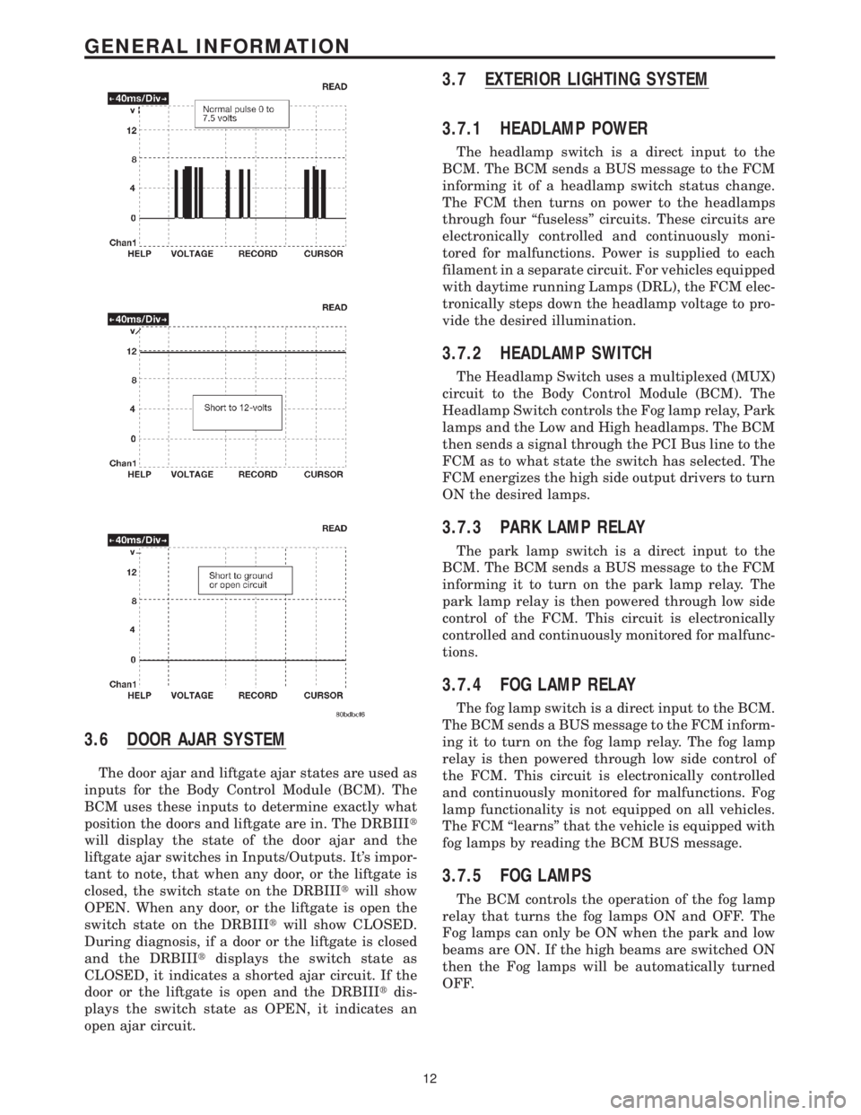
3.6 DOOR AJAR SYSTEM
The door ajar and liftgate ajar states are used as
inputs for the Body Control Module (BCM). The
BCM uses these inputs to determine exactly what
position the doors and liftgate are in. The DRBIIIt
will display the state of the door ajar and the
liftgate ajar switches in Inputs/Outputs. It's impor-
tant to note, that when any door, or the liftgate is
closed, the switch state on the DRBIIItwill show
OPEN. When any door, or the liftgate is open the
switch state on the DRBIIItwill show CLOSED.
During diagnosis, if a door or the liftgate is closed
and the DRBIIItdisplays the switch state as
CLOSED, it indicates a shorted ajar circuit. If the
door or the liftgate is open and the DRBIIItdis-
plays the switch state as OPEN, it indicates an
open ajar circuit.
3.7 EXTERIOR LIGHTING SYSTEM
3.7.1 HEADLAMP POWER
The headlamp switch is a direct input to the
BCM. The BCM sends a BUS message to the FCM
informing it of a headlamp switch status change.
The FCM then turns on power to the headlamps
through four ªfuselessº circuits. These circuits are
electronically controlled and continuously moni-
tored for malfunctions. Power is supplied to each
filament in a separate circuit. For vehicles equipped
with daytime running Lamps (DRL), the FCM elec-
tronically steps down the headlamp voltage to pro-
vide the desired illumination.
3.7.2 HEADLAMP SWITCH
The Headlamp Switch uses a multiplexed (MUX)
circuit to the Body Control Module (BCM). The
Headlamp Switch controls the Fog lamp relay, Park
lamps and the Low and High headlamps. The BCM
then sends a signal through the PCI Bus line to the
FCM as to what state the switch has selected. The
FCM energizes the high side output drivers to turn
ON the desired lamps.
3.7.3 PARK LAMP RELAY
The park lamp switch is a direct input to the
BCM. The BCM sends a BUS message to the FCM
informing it to turn on the park lamp relay. The
park lamp relay is then powered through low side
control of the FCM. This circuit is electronically
controlled and continuously monitored for malfunc-
tions.
3.7.4 FOG LAMP RELAY
The fog lamp switch is a direct input to the BCM.
The BCM sends a BUS message to the FCM inform-
ing it to turn on the fog lamp relay. The fog lamp
relay is then powered through low side control of
the FCM. This circuit is electronically controlled
and continuously monitored for malfunctions. Fog
lamp functionality is not equipped on all vehicles.
The FCM ªlearnsº that the vehicle is equipped with
fog lamps by reading the BCM BUS message.
3.7.5 FOG LAMPS
The BCM controls the operation of the fog lamp
relay that turns the fog lamps ON and OFF. The
Fog lamps can only be ON when the park and low
beams are ON. If the high beams are switched ON
then the Fog lamps will be automatically turned
OFF.
12
GENERAL INFORMATION