torque CHRYSLER VOYAGER 2001 User Guide
[x] Cancel search | Manufacturer: CHRYSLER, Model Year: 2001, Model line: VOYAGER, Model: CHRYSLER VOYAGER 2001Pages: 4284, PDF Size: 83.53 MB
Page 1484 of 4284
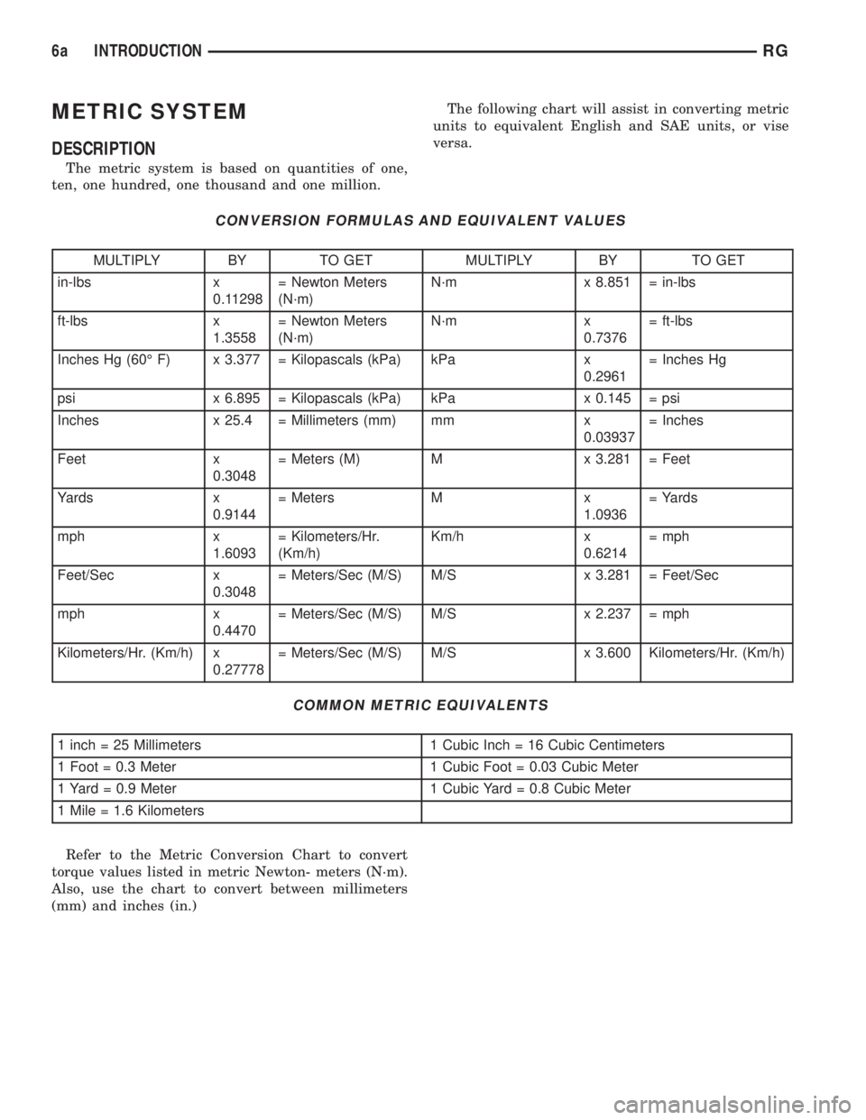
METRIC SYSTEM
DESCRIPTION
The metric system is based on quantities of one,
ten, one hundred, one thousand and one million.The following chart will assist in converting metric
units to equivalent English and SAE units, or vise
versa.
CONVERSION FORMULAS AND EQUIVALENT VALUES
MULTIPLY BY TO GET MULTIPLY BY TO GET
in-lbs x
0.11298= Newton Meters
(N´m)N´m x 8.851 = in-lbs
ft-lbs x
1.3558= Newton Meters
(N´m)N´m x
0.7376= ft-lbs
Inches Hg (60É F) x 3.377 = Kilopascals (kPa) kPa x
0.2961= Inches Hg
psi x 6.895 = Kilopascals (kPa) kPa x 0.145 = psi
Inches x 25.4 = Millimeters (mm) mm x
0.03937= Inches
Feet x
0.3048= Meters (M) M x 3.281 = Feet
Yards x
0.9144= Meters M x
1.0936= Yards
mph x
1.6093= Kilometers/Hr.
(Km/h)Km/h x
0.6214= mph
Feet/Sec x
0.3048= Meters/Sec (M/S) M/S x 3.281 = Feet/Sec
mph x
0.4470= Meters/Sec (M/S) M/S x 2.237 = mph
Kilometers/Hr. (Km/h) x
0.27778= Meters/Sec (M/S) M/S x 3.600 Kilometers/Hr. (Km/h)
COMMON METRIC EQUIVALENTS
1 inch = 25 Millimeters 1 Cubic Inch = 16 Cubic Centimeters
1 Foot = 0.3 Meter 1 Cubic Foot = 0.03 Cubic Meter
1 Yard = 0.9 Meter 1 Cubic Yard = 0.8 Cubic Meter
1 Mile = 1.6 Kilometers
Refer to the Metric Conversion Chart to convert
torque values listed in metric Newton- meters (N´m).
Also, use the chart to convert between millimeters
(mm) and inches (in.)
6a INTRODUCTIONRG
Page 1486 of 4284
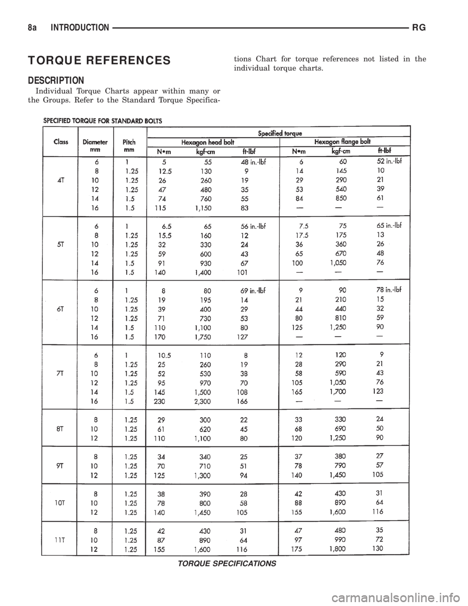
TORQUE REFERENCES
DESCRIPTION
Individual Torque Charts appear within many or
the Groups. Refer to the Standard Torque Specifica-tions Chart for torque references not listed in the
individual torque charts.
TORQUE SPECIFICATIONS
8a INTRODUCTIONRG
Page 1492 of 4284
CONTAINER IDENTIFICATION
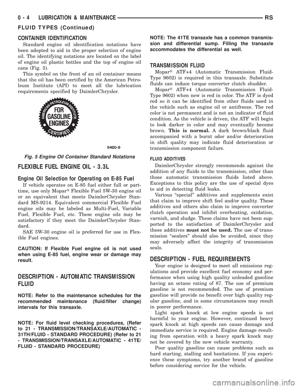
Standard engine oil identification notations have
been adopted to aid in the proper selection of engine
oil. The identifying notations are located on the label
of engine oil plastic bottles and the top of engine oil
cans (Fig. 5).
This symbol on the front of an oil container means
that the oil has been certified by the American Petro-
leum Institute (API) to meet all the lubrication
requirements specified by DaimlerChrysler.
FLEXIBLE FUEL ENGINE OIL - 3.3L
Engine Oil Selection for Operating on E-85 Fuel
If vehicle operates on E-85 fuel either full or part-
time, use only MopartFlexible Fuel 5W-30 engine oil
or an equivalent that meets DaimlerChrysler Stan-
dard MS-9214. Equivalent commercial Flexible Fuel
engine oils may be labeled as Multi-Fuel, Variable
Fuel, Flexible Fuel, etc. These engine oils may be
satisfactory if they meet the DaimlerChrysler Stan-
dard.
SAE 5W-30 engine oil is preferred for use in Flex-
ible Fuel engines.
CAUTION: If Flexible Fuel engine oil is not used
when using E-85 fuel, engine wear or damage may
result.
DESCRIPTION - AUTOMATIC TRANSMISSION
FLUID
NOTE: Refer to the maintenance schedules for the
recommended maintenance (fluid/filter change)
intervals for this transaxle.
NOTE: For fluid level checking procedures, (Refer
to 21 - TRANSMISSION/TRANSAXLE/AUTOMATIC -
31TH/FLUID - STANDARD PROCEDURE) (Refer to 21
- TRANSMISSION/TRANSAXLE/AUTOMATIC - 41TE/
FLUID - STANDARD PROCEDURE)NOTE: The 41TE transaxle has a common transmis-
sion and differential sump. Filling the transaxle
accommodates the differential as well.
TRANSMISSION FLUID
MopartATF+4 (Automatic Transmission Fluid-
Type 9602) is required in this transaxle. Substitute
fluids can induce torque converter clutch shudder.
MopartATF+4 (Automatic Transmission Fluid-
Type 9602) when new is red in color. The ATF is dyed
red so it can be identified from other fluids used in
the vehicle such as engine oil or antifreeze. The red
color is not permanent and is not an indicator of fluid
condition. As the vehicle is driven, the ATF will begin
to look darker in color and may eventually become
brown.This is normal.A dark brown/black fluid
accompanied with a burnt odor and/or deterioration
in shift quality may indicate fluid deterioration or
transmission component failure.
FLUID ADDITIVES
DaimlerChrysler strongly recommends against the
addition of any fluids to the transmission, other than
those automatic transmission fluids listed above.
Exceptions to this policy are the use of special dyes
to aid in detecting fluid leaks.
Various ªspecialº additives and supplements exist
that claim to improve shift feel and/or quality. These
additives and others also claim to improve converter
clutch operation and inhibit overheating, oxidation,
varnish, and sludge. These claims have not been sup-
ported to the satisfaction of DaimlerChrysler and
these additivesmust not be used.The use of trans-
mission ªsealersº should also be avoided, since they
may adversely affect the integrity of transmission
seals.
DESCRIPTION - FUEL REQUIREMENTS
Your engine is designed to meet all emissions reg-
ulations and provide excellent fuel economy and per-
formance when using high quality unleaded gasoline
having an octane rating of 87. The use of premium
gasoline is not recommended. The use of premium
gasoline will provide no benefit over high quality reg-
ular gasoline, and in some circumstances may result
in poorer performance.
Light spark knock at low engine speeds is not
harmful to your engine. However, continued heavy
spark knock at high speeds can cause damage and
immediate service is required. Engine damage result-
ing from operation with a heavy spark knock may
not be covered by the new vehicle warranty.
Poor quality gasoline can cause problems such as
hard starting, stalling and hesitations. If you experi-
ence these symptoms, try another brand of gasoline
before considering service for the vehicle.
Fig. 5 Engine Oil Container Standard Notations
0 - 4 LUBRICATION & MAINTENANCERS
FLUID TYPES (Continued)
Page 1509 of 4284
LUBRICANTS AND GREASES
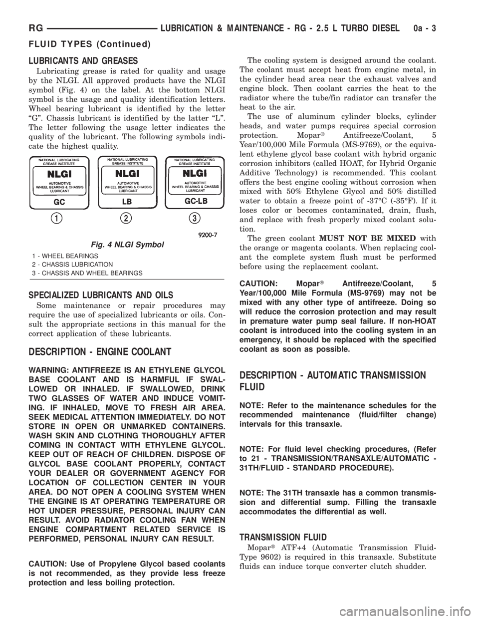
Lubricating grease is rated for quality and usage
by the NLGI. All approved products have the NLGI
symbol (Fig. 4) on the label. At the bottom NLGI
symbol is the usage and quality identification letters.
Wheel bearing lubricant is identified by the letter
ªGº. Chassis lubricant is identified by the latter ªLº.
The letter following the usage letter indicates the
quality of the lubricant. The following symbols indi-
cate the highest quality.
SPECIALIZED LUBRICANTS AND OILS
Some maintenance or repair procedures may
require the use of specialized lubricants or oils. Con-
sult the appropriate sections in this manual for the
correct application of these lubricants.
DESCRIPTION - ENGINE COOLANT
WARNING: ANTIFREEZE IS AN ETHYLENE GLYCOL
BASE COOLANT AND IS HARMFUL IF SWAL-
LOWED OR INHALED. IF SWALLOWED, DRINK
TWO GLASSES OF WATER AND INDUCE VOMIT-
ING. IF INHALED, MOVE TO FRESH AIR AREA.
SEEK MEDICAL ATTENTION IMMEDIATELY. DO NOT
STORE IN OPEN OR UNMARKED CONTAINERS.
WASH SKIN AND CLOTHING THOROUGHLY AFTER
COMING IN CONTACT WITH ETHYLENE GLYCOL.
KEEP OUT OF REACH OF CHILDREN. DISPOSE OF
GLYCOL BASE COOLANT PROPERLY, CONTACT
YOUR DEALER OR GOVERNMENT AGENCY FOR
LOCATION OF COLLECTION CENTER IN YOUR
AREA. DO NOT OPEN A COOLING SYSTEM WHEN
THE ENGINE IS AT OPERATING TEMPERATURE OR
HOT UNDER PRESSURE, PERSONAL INJURY CAN
RESULT. AVOID RADIATOR COOLING FAN WHEN
ENGINE COMPARTMENT RELATED SERVICE IS
PERFORMED, PERSONAL INJURY CAN RESULT.
CAUTION: Use of Propylene Glycol based coolants
is not recommended, as they provide less freeze
protection and less boiling protection.The cooling system is designed around the coolant.
The coolant must accept heat from engine metal, in
the cylinder head area near the exhaust valves and
engine block. Then coolant carries the heat to the
radiator where the tube/fin radiator can transfer the
heat to the air.
The use of aluminum cylinder blocks, cylinder
heads, and water pumps requires special corrosion
protection. MopartAntifreeze/Coolant, 5
Year/100,000 Mile Formula (MS-9769), or the equiva-
lent ethylene glycol base coolant with hybrid organic
corrosion inhibitors (called HOAT, for Hybrid Organic
Additive Technology) is recommended. This coolant
offers the best engine cooling without corrosion when
mixed with 50% Ethylene Glycol and 50% distilled
water to obtain a freeze point of -37ÉC (-35ÉF). If it
loses color or becomes contaminated, drain, flush,
and replace with fresh properly mixed coolant solu-
tion.
The green coolantMUST NOT BE MIXEDwith
the orange or magenta coolants. When replacing cool-
ant the complete system flush must be performed
before using the replacement coolant.
CAUTION: MoparTAntifreeze/Coolant, 5
Year/100,000 Mile Formula (MS-9769) may not be
mixed with any other type of antifreeze. Doing so
will reduce the corrosion protection and may result
in premature water pump seal failure. If non-HOAT
coolant is introduced into the cooling system in an
emergency, it should be replaced with the specified
coolant as soon as possible.DESCRIPTION - AUTOMATIC TRANSMISSION
FLUID
NOTE: Refer to the maintenance schedules for the
recommended maintenance (fluid/filter change)
intervals for this transaxle.
NOTE: For fluid level checking procedures, (Refer
to 21 - TRANSMISSION/TRANSAXLE/AUTOMATIC -
31TH/FLUID - STANDARD PROCEDURE).
NOTE: The 31TH transaxle has a common transmis-
sion and differential sump. Filling the transaxle
accommodates the differential as well.
TRANSMISSION FLUID
MopartATF+4 (Automatic Transmission Fluid-
Type 9602) is required in this transaxle. Substitute
fluids can induce torque converter clutch shudder.
Fig. 4 NLGI Symbol
1 - WHEEL BEARINGS
2 - CHASSIS LUBRICATION
3 - CHASSIS AND WHEEL BEARINGS
RGLUBRICATION & MAINTENANCE - RG - 2.5 L TURBO DIESEL0a-3
FLUID TYPES (Continued)
Page 1519 of 4284
SPECIFICATIONS
FRONT SUSPENSION FASTENER TORQUE
DESCRIPTION N´mFt.
Lbs.In.
Lbs.
Ball Joint Nut 108 80 Ð
Cradle Crossmember
Mounting Bolts163 120 Ð
Disc Brake Adapter
Mounting Bolts169 125 Ð
Hub And Bearing Mounting
Bolts65 45 Ð
Hub And Bearing Axle Hub
Nut244 180 Ð
Lower Control Arm Pivot
Bolt183 135 Ð
Lower Control Arm Rear
Bushing Retainer bolts61 45 Ð
Stabilizer Bar Bushing
Retainer Bolts68 50 Ð
Stabilizer Bar Link Nuts 88 65 Ð
Strut Body/Tower Mounting
Nuts28 21 250
Strut Clevis-to-Knuckle Nuts 81 +
90É
turn60 +
90É
turnÐ
Strut Shaft Nut 100 75 Ð
Tie Rod Adjuster Jam Nut 75 55 Ð
Tie Rod Steering Arm Nut 75 55 Ð
Wheel Mounting (Lug) Nuts 135 100 Ð
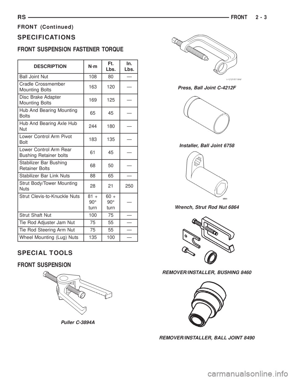
SPECIAL TOOLS
FRONT SUSPENSION
Puller C-3894A
Press, Ball Joint C-4212F
Installer, Ball Joint 6758
Wrench, Strut Rod Nut 6864
REMOVER/INSTALLER, BUSHING 8460
REMOVER/INSTALLER, BALL JOINT 8490
RSFRONT2-3
FRONT (Continued)
Page 1520 of 4284
BUSHINGS
REMOVAL - STABILIZER BAR CUSHION
(1) Raise Vehicle. Refer to Hoisting in Lubrication
and Maintenance.
(2) Remove the 2 bolts fastening the emission leak
detection pump to the cradle crossmember reinforce-
ment.
(3) Move the leak detection pump to the side
allowing access to the stabilizer bar cushion retain-
ers.
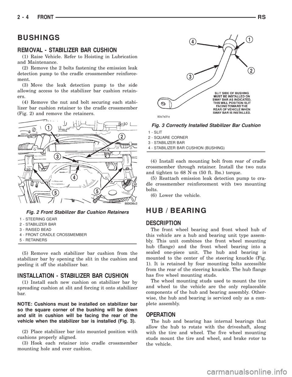
(4) Remove the nut and bolt securing each stabi-
lizer bar cushion retainer to the cradle crossmember
(Fig. 2) and remove the retainers.
(5) Remove each stabilizer bar cushion from the
stabilizer bar by opening the slit in the cushion and
peeling it off the stabilizer bar.
INSTALLATION - STABILIZER BAR CUSHION
(1) Install each new cushion on stabilizer bar by
spreading cushion at slit and forcing it onto stabilizer
bar.
NOTE: Cushions must be installed on stabilizer bar
so the square corner of the bushing will be down
and slit in cushion will be facing the rear of the
vehicle when the stabilizer bar is installed (Fig. 3).
(2) Place stabilizer bar into mounted position with
cushions properly aligned.
(3) Hook each retainer into cradle crossmember
mounting hole and over cushion.(4) Install each mounting bolt from rear of cradle
crossmember through retainer. Install the two nuts
and tighten to 68 N´m (50 ft. lbs.) torque.
(5) Reattach emission leak detection pump to cra-
dle crossmember reinforcement with two mounting
bolts.
(6) Lower the vehicle.
HUB / BEARING
DESCRIPTION
The front wheel bearing and front wheel hub of
this vehicle are a hub and bearing unit type assem-
bly. This unit combines the front wheel mounting
hub (flange) and the front wheel bearing into a
sealed one-piece unit. The hub and bearing is
mounted to the center of the steering knuckle (Fig.
1). It is retained by four mounting bolts accessible
from the rear of the steering knuckle. The hub flange
has five wheel mounting studs.
The wheel mounting studs used to mount the tire
and wheel to the vehicle are the only replaceable
components of the hub and bearing assembly. Other-
wise, the hub and bearing is serviced only as a com-
plete assembly.
OPERATION
The hub and bearing has internal bearings that
allow the hub to rotate with the driveshaft, along
with the tire and wheel. The five wheel mounting
studs mount the tire and wheel, and brake rotor to
the vehicle.
Fig. 2 Front Stabilizer Bar Cushion Retainers
1 - STEERING GEAR
2 - STABILIZER BAR
3 - RAISED BEAD
4 - FRONT CRADLE CROSSMEMBER
5 - RETAINERS
Fig. 3 Correctly Installed Stabilizer Bar Cushion
1 - SLIT
2 - SQUARE CORNER
3 - STABILIZER BAR
4 - STABILIZER BAR CUSHION (BUSHING)
2 - 4 FRONTRS
Page 1522 of 4284
INSTALLATION - HUB AND BEARING
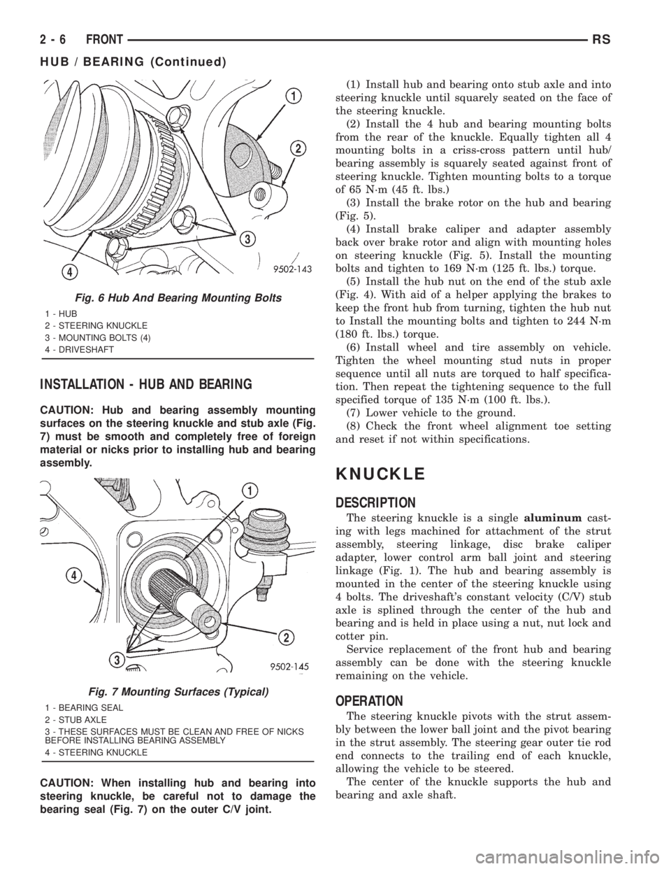
CAUTION: Hub and bearing assembly mounting
surfaces on the steering knuckle and stub axle (Fig.
7) must be smooth and completely free of foreign
material or nicks prior to installing hub and bearing
assembly.
CAUTION: When installing hub and bearing into
steering knuckle, be careful not to damage the
bearing seal (Fig. 7) on the outer C/V joint.(1) Install hub and bearing onto stub axle and into
steering knuckle until squarely seated on the face of
the steering knuckle.
(2) Install the 4 hub and bearing mounting bolts
from the rear of the knuckle. Equally tighten all 4
mounting bolts in a criss-cross pattern until hub/
bearing assembly is squarely seated against front of
steering knuckle. Tighten mounting bolts to a torque
of 65 N´m (45 ft. lbs.)
(3) Install the brake rotor on the hub and bearing
(Fig. 5).
(4) Install brake caliper and adapter assembly
back over brake rotor and align with mounting holes
on steering knuckle (Fig. 5). Install the mounting
bolts and tighten to 169 N´m (125 ft. lbs.) torque.
(5) Install the hub nut on the end of the stub axle
(Fig. 4). With aid of a helper applying the brakes to
keep the front hub from turning, tighten the hub nut
to Install the mounting bolts and tighten to 244 N´m
(180 ft. lbs.) torque.
(6) Install wheel and tire assembly on vehicle.
Tighten the wheel mounting stud nuts in proper
sequence until all nuts are torqued to half specifica-
tion. Then repeat the tightening sequence to the full
specified torque of 135 N´m (100 ft. lbs.).
(7) Lower vehicle to the ground.
(8) Check the front wheel alignment toe setting
and reset if not within specifications.
KNUCKLE
DESCRIPTION
The steering knuckle is a singlealuminumcast-
ing with legs machined for attachment of the strut
assembly, steering linkage, disc brake caliper
adapter, lower control arm ball joint and steering
linkage (Fig. 1). The hub and bearing assembly is
mounted in the center of the steering knuckle using
4 bolts. The driveshaft's constant velocity (C/V) stub
axle is splined through the center of the hub and
bearing and is held in place using a nut, nut lock and
cotter pin.
Service replacement of the front hub and bearing
assembly can be done with the steering knuckle
remaining on the vehicle.
OPERATION
The steering knuckle pivots with the strut assem-
bly between the lower ball joint and the pivot bearing
in the strut assembly. The steering gear outer tie rod
end connects to the trailing end of each knuckle,
allowing the vehicle to be steered.
The center of the knuckle supports the hub and
bearing and axle shaft.
Fig. 6 Hub And Bearing Mounting Bolts
1 - HUB
2 - STEERING KNUCKLE
3 - MOUNTING BOLTS (4)
4 - DRIVESHAFT
Fig. 7 Mounting Surfaces (Typical)
1 - BEARING SEAL
2 - STUB AXLE
3 - THESE SURFACES MUST BE CLEAN AND FREE OF NICKS
BEFORE INSTALLING BEARING ASSEMBLY
4 - STEERING KNUCKLE
2 - 6 FRONTRS
HUB / BEARING (Continued)
Page 1525 of 4284
(13) Remove the steering knuckle from the vehicle.
(14) If the hub and bearing needs to be trans-
ferred, remove the four bolts attaching the hub and
bearing to the knuckle, then remove the hub and
bearing.
INSPECTION - STEERING KNUCKLE
Inspect the knuckle for the following:
²Cracks or breaks
²Dents or damage
²Stress marks indicating a bend
The front suspension knuckle is not a repairable
component of the vehicles front suspension. If bent,
broken or damaged in any way, do not attempt to
straighten or repair the steering knuckle. It must be
replaced.
If inspection leads to the hub and bearing, (Refer
to 2 - SUSPENSION/FRONT/HUB / BEARING -
DIAGNOSIS AND TESTING)
INSTALLATION - STEERING KNUCKLE
(1) If the hub and bearing needs to be installed in
the knuckle, place the hub and bearing squarely into
the center hole of the steering knuckle aligning the
threaded mounting holes of the hub and bearing with
the mounting holes in the steering knuckle. Installthe four mounting bolts and tighten them to a torque
of 65 N´m (45 ft. lbs.).
CAUTION: Before installing the knuckle on the ball
joint stud, wipe the ball joint stud and knuckle con-
tact area free of any grease or debris, otherwise
damage to the knuckle can occur. Use a clean shop
cloth with MoparTBrake Parts Cleaner applied to it
for proper cleaning.
(2) Place the knuckle on the ball joint stud.
(3) Install a NEW steering knuckle to ball joint
stud nut. Tighten the nut by holding ball joint stud
with hex wrench while turning nut with a wrench
(Fig. 14). Using a crowsfoot wrench on a torque
wrench, tighten the nut to a torque of 108 N´m (80 ft.
lbs.).
(4) Slide driveshaft stub axle into hub and bearing
assembly.
CAUTION: The steering knuckle to strut assembly
attaching bolts are serrated and must not be turned
during installation. Install nuts while holding bolts
stationary in the steering knuckle.
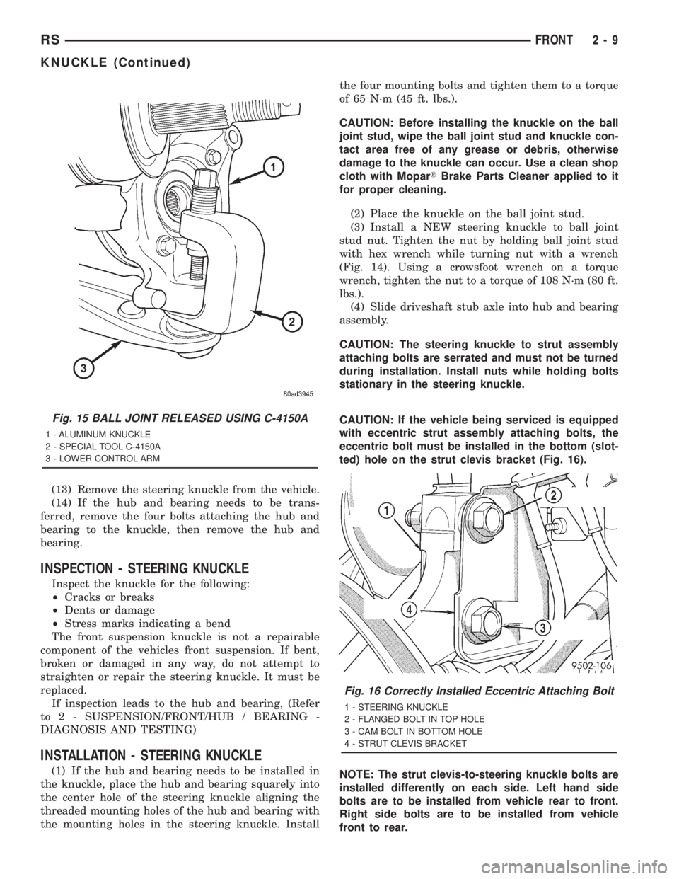
CAUTION: If the vehicle being serviced is equipped
with eccentric strut assembly attaching bolts, the
eccentric bolt must be installed in the bottom (slot-
ted) hole on the strut clevis bracket (Fig. 16).
NOTE: The strut clevis-to-steering knuckle bolts are
installed differently on each side. Left hand side
bolts are to be installed from vehicle rear to front.
Right side bolts are to be installed from vehicle
front to rear.
Fig. 15 BALL JOINT RELEASED USING C-4150A
1 - ALUMINUM KNUCKLE
2 - SPECIAL TOOL C-4150A
3 - LOWER CONTROL ARM
Fig. 16 Correctly Installed Eccentric Attaching Bolt
1 - STEERING KNUCKLE
2 - FLANGED BOLT IN TOP HOLE
3 - CAM BOLT IN BOTTOM HOLE
4 - STRUT CLEVIS BRACKET
RSFRONT2-9
KNUCKLE (Continued)
Page 1526 of 4284
(5) Install steering knuckle in clevis bracket of
strut damper assembly. Install the strut clevis-to-
steering knuckle attaching bolts. Tighten both bolts
to a torque of 81 N´m (60 ft. lbs.) plus an additional
1/4 (90É) turn.
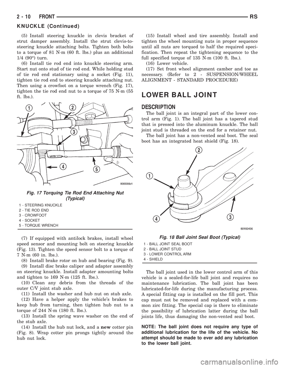
(6) Install tie rod end into knuckle steering arm.
Start nut onto stud of tie rod end. While holding stud
of tie rod end stationary using a socket (Fig. 11),
tighten tie rod end to steering knuckle attaching nut.
Then using a crowfoot on a torque wrench (Fig. 17),
tighten the tie rod end nut to a torque of 75 N´m (55
ft. lbs.).
(7) If equipped with antilock brakes, install wheel
speed sensor and mounting bolt on steering knuckle
(Fig. 13). Tighten the speed sensor bolt to a torque of
7 N´m (60 in. lbs.).
(8) Install brake rotor on hub and bearing (Fig. 9).
(9) Install disc brake caliper and adapter assembly
on steering knuckle. Install adapter amounting bolts
and tighten to 169 N´m (125 ft. lbs.).
(10) Clean any debris from the threads of the
outer C/V joint stub axle.
(11) Install the washer and hub nut on stub axle.
(12) Have a helper apply the vehicle's brakes to
keep hub from turning, then tighten hub nut to a
torque of 244 N´m (180 ft. lbs.).
(13) Install the spring wave washer on the end of
the stub axle.
(14) Install the hub nut lock, and anewcotter pin
(Fig. 8). Wrap cotter pin prongs tightly around the
hub nut lock.(15) Install wheel and tire assembly. Install and
tighten the wheel mounting nuts in proper sequence
until all nuts are torqued to half the required speci-
fication. Then repeat the tightening sequence to the
full specified torque of 135 N´m (100 ft. lbs.).
(16) Lower vehicle.
(17) Set front wheel alignment camber and toe as
necessary. (Refer to 2 - SUSPENSION/WHEEL
ALIGNMENT - STANDARD PROCEDURE)
LOWER BALL JOINT
DESCRIPTION
The ball joint is an integral part of the lower con-
trol arm (Fig. 1). The ball joint has a tapered stud
that is pressed into the aluminum knuckle. The ball
joint stud is threaded on the end for a retainer nut.
The ball joint has a non-vented seal boot. The seal
boot has an integrated heat shield (Fig. 18).
The ball joint used in the lower control arm of this
vehicle is a sealed-for-life ball joint and requires no
maintenance lubrication. The ball joint has been
lubricated-for-life during the manufacturing process.
A special fitting cap is installed on the fill port. This
cap must not be removed and replaced with a com-
mon zirc fitting. The special cap is there to eliminate
the possibility of lubrication latter during the ball
joints life, thus damaging the non-vented seal boot.
NOTE: The ball joint does not require any type of
additional lubrication for the life of the vehicle. No
attempt should be made to ever add any lubrication
to the lower ball joint.
Fig. 17 Torquing Tie Rod End Attaching Nut
(Typical)
1 - STEERING KNUCKLE
2 - TIE ROD END
3 - CROWFOOT
4 - SOCKET
5 - TORQUE WRENCH
Fig. 18 Ball Joint Seal Boot (Typical)
1 - BALL JOINT SEAL BOOT
2 - BALL JOINT STUD
3 - LOWER CONTROL ARM
4 - SHIELD
2 - 10 FRONTRS
KNUCKLE (Continued)
Page 1530 of 4284
type rear bushings are serviceable. If the front bush-
ing fails, the lower control arm must be replaced.
Inspect and test the ball joint per the procedure
listed in Lower Ball Joint. (Refer to 2 - SUSPEN-
SION/FRONT/LOWER BALL JOINT - DIAGNOSIS
AND TESTING)
ASSEMBLY - LOWER CONTROL ARM (REAR
BUSHING - STANDARD)
CAUTION: Do not apply grease or any other type of
lubricant other than the silicone lubricant specified
below to the control arm bushing.
(1) Apply Mopar Silicone Spray Lube or an equiv-
alent, to the hole in lower control arm rear bushing.
This will aid in the installation of the bushing on the
lower control arm.
(2) With the lower control arm held securely in a
vise, install bushing on lower control arm. Install
bushing by pushing and rocking the bushing until it
is fully installed on lower control arm. Be sure that
when bushing is installed it is past the upset on the
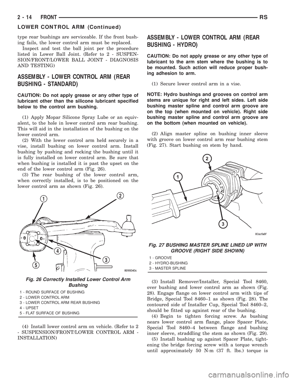
end of the lower control arm (Fig. 26).
(3) The rear bushing of the lower control arm,
when correctly installed, is to be positioned on the
lower control arm as shown (Fig. 26).
(4) Install lower control arm on vehicle. (Refer to 2
- SUSPENSION/FRONT/LOWER CONTROL ARM -
INSTALLATION)
ASSEMBLY - LOWER CONTROL ARM (REAR
BUSHING - HYDRO)
CAUTION: Do not apply grease or any other type of
lubricant to the arm stem where the bushing is to
be mounted. Such action will reduce proper bush-
ing adhesion to arm.
(1) Secure lower control arm in a vise.
NOTE: Hydro bushings and grooves on control arm
stems are unique for right and left sides. Left side
bushing master spline and control arm groove are
on the top (when mounted on vehicle). Right side
bushing master spline and control arm groove are
on the bottom (when mounted on vehicle).
(2) Align master spline on bushing inner sleeve
with groove on lower control arm rear bushing stem
(Fig. 27). Start bushing on stem by hand.
(3) Install Remover/Installer, Special Tool 8460,
over bushing and lower control arm as shown (Fig.
28). Engage flange on lower control arm with tips of
Bridge, Special Tool 8460±1 as shown (Fig. 28). The
contoured side of Installer Cup, Special Tool 8460±2,
should be fitted up against rear of the bushing.
(4) Begin to tighten forcing screw. As bushing
nears lower control arm flange, place Spacer Plate,
Special Tool 8460±4 between flange and bushing
inner sleeve, straddling the stem as shown (Fig. 29).
(5) Install bushing up against Spacer Plate, tight-
ening the bridge forcing screw with a torque wrench
until approximately 50 N´m (37 ft. lbs.) torque is
Fig. 26 Correctly Installed Lower Control Arm
Bushing
1 - ROUND SURFACE OF BUSHING
2 - LOWER CONTROL ARM
3 - LOWER CONTROL ARM REAR BUSHING
4 - UPSET
5 - FLAT SURFACE OF BUSHING
Fig. 27 BUSHING MASTER SPLINE LINED UP WITH
GROOVE (RIGHT SIDE SHOWN)
1 - GROOVE
2 - HYDRO-BUSHING
3 - MASTER SPLINE
2 - 14 FRONTRS
LOWER CONTROL ARM (Continued)