torque CHRYSLER VOYAGER 2001 Workshop Manual
[x] Cancel search | Manufacturer: CHRYSLER, Model Year: 2001, Model line: VOYAGER, Model: CHRYSLER VOYAGER 2001Pages: 4284, PDF Size: 83.53 MB
Page 1594 of 4284

SPECIFICATIONS
SPECIFICATIONS - HALF SHAFT - FRONT
TORQUE SPECIFICATIONS
DESCRIPTION N´m Ft. Lbs. In. Lbs.
Nut, Hub 244 180 -
Nuts, Rear Wheel Lug 135 100 -
Bolt, Half Shaft to Output Flange 61 45 -
CV BOOT - INNER/OUTER
REMOVAL
(1) Remove half shaft from vehicle. (Refer to 3 -
DIFFERENTIAL & DRIVELINE/HALF SHAFT -
REMOVAL)
(2) Clamp the half shaft into a suitable vise with
protective jaws clamped onto the interconnecting
shaft (Fig. 7).
(3) Remove the large and small diameter retaining
clamps holding the CV boot to the CV joint and the
interconnecting shaft (Fig. 8).
(4) Pull the boot back from the CV joint (Fig. 9).
(5) Remove the CV housing from the interconnect-
ing shaft and tripod assembly (Fig. 10).
(6) Remove the snap-ring holding the tripod
assembly onto the interconnecting shaft (Fig. 11).
Fig. 5 Inner Half Shaft Bolts
1 - SHAFT
2 - FLANGE
Fig. 6 Cotter Pin, Nut Lock, And Wave Washer
1 - HUB NUT
2 - NUT LOCK
3 - COTTER PIN
4 - WAVE WASHER
Fig. 7 Clamp Shaft In Soft Jawed Vice
1 - HALF SHAFT BOOT
2 - HALF SHAFT
3 - VISE
3 - 18 HALF SHAFT - REARRS
HALF SHAFT - REAR (Continued)
Page 1600 of 4284
PROPELLER SHAFT
TABLE OF CONTENTS
page page
PROPELLER SHAFT
DESCRIPTION...........................24
OPERATION.............................24REMOVAL..............................24
INSTALLATION...........................24
SPECIFICATIONS........................25
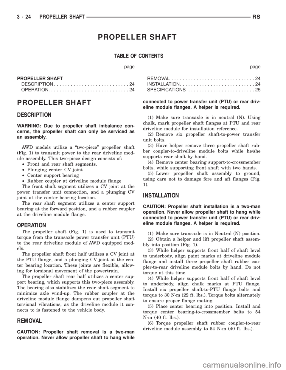
PROPELLER SHAFT
DESCRIPTION
WARNING: Due to propeller shaft imbalance con-
cerns, the propeller shaft can only be serviced as
an assembly.
AWD models utilize a ªtwo-pieceº propeller shaft
(Fig. 1) to transmit power to the rear driveline mod-
ule assembly. This two-piece design consists of:
²Front and rear shaft segments.
²Plunging center CV joint
²Center support bearing
²Rubber coupler at driveline module flange
The front shaft segment utilizes a CV joint at the
power transfer unit connection, and a plunging CV
joint at the center bearing location.
The rear shaft segment utilizes a center support
bearing at the forward position, and a rubber coupler
at the driveline module flange.
OPERATION
The propeller shaft (Fig. 1) is used to transmit
torque from the transaxle power transfer unit (PTU)
to the rear driveline module of AWD equipped mod-
els.
The propeller shaft front half utilizes a CV joint at
the PTU flange, and a plunging CV joint at the cen-
ter bearing location. These joints are flexible, allow-
ing for torsional movement of the powertrain.
The propeller shaft rear half utilizes a center sup-
port bearing, which supports this two-piece assembly.
The bearing also stabilizes the rear shaft segment to
minimize axle wind-up. The rubber coupler at the
driveline module flange dampens out propeller shaft
torsional vibrations, as the driveline module it con-
nects to is fastened to the vehicle body.
REMOVAL
CAUTION: Propeller shaft removal is a two-man
operation. Never allow propeller shaft to hang whileconnected to power transfer unit (PTU) or rear driv-
eline module flanges. A helper is required.
(1) Make sure transaxle is in neutral (N). Using
chalk, mark propeller shaft flanges at PTU and rear
driveline module for installation reference.
(2) Remove six propeller shaft-to-power transfer
unit bolts.
(3) Have helper remove three propeller shaft rub-
ber coupler-to-driveline module bolts while he/she
supports rear shaft by hand.
(4) Remove center bearing support-to-crossmember
bolts, while supporting front shaft with two hands.
(5) Lower propeller shaft assembly to ground,
using care not to damage fore and aft flanges (Fig.
1).
INSTALLATION
CAUTION: Propeller shaft installation is a two-man
operation. Never allow propeller shaft to hang while
connected to power transfer unit (PTU) or rear driv-
eline module flanges. A helper is required.
(1) Make sure transaxle is in Neutral (N) position.
(2) Obtain a helper and lift propeller shaft assem-
bly into position (Fig. 1).
(3) While helper supports front half of shaft level
to underbody, align paint marks at driveline module
flange and install three propeller shaft rubber cou-
pler-to-rear driveline module bolts by hand. Do not
torque at this time.
(4) While helper supports front half of shaft level
to underbody, align chalk marks at PTU flange.
Install six propeller shaft-to-PTU flange bolts and
torque to 30 N´m (22 ft. lbs.). Torque bolts alternately
to ensure proper flange mating.
(5) Place center bearing into position. Install and
torque center bearing-to-crossmember bolts to 54
N´m (40 ft. lbs.).
(6) Torque propeller shaft rubber coupler-to-rear
driveline module assembly to 54 N´m (40 ft. lbs.).
3 - 24 PROPELLER SHAFTRS
Page 1601 of 4284
SPECIFICATIONS
SPECIFICATIONS - PROPELLER SHAFT
TORQUE SPECIFICATIONS
DESCRIPTION N´m Ft. Lbs. In. Lbs.
Bolt, Propeller Shaft Front Flange-to-PTU
Flange30 22 Ð
Bolt, Propeller Shaft Rear Flange-to-
Driveline Module Flange54 40 Ð
Bolt, Center Support Bearing-to-Body 54 40 Ð
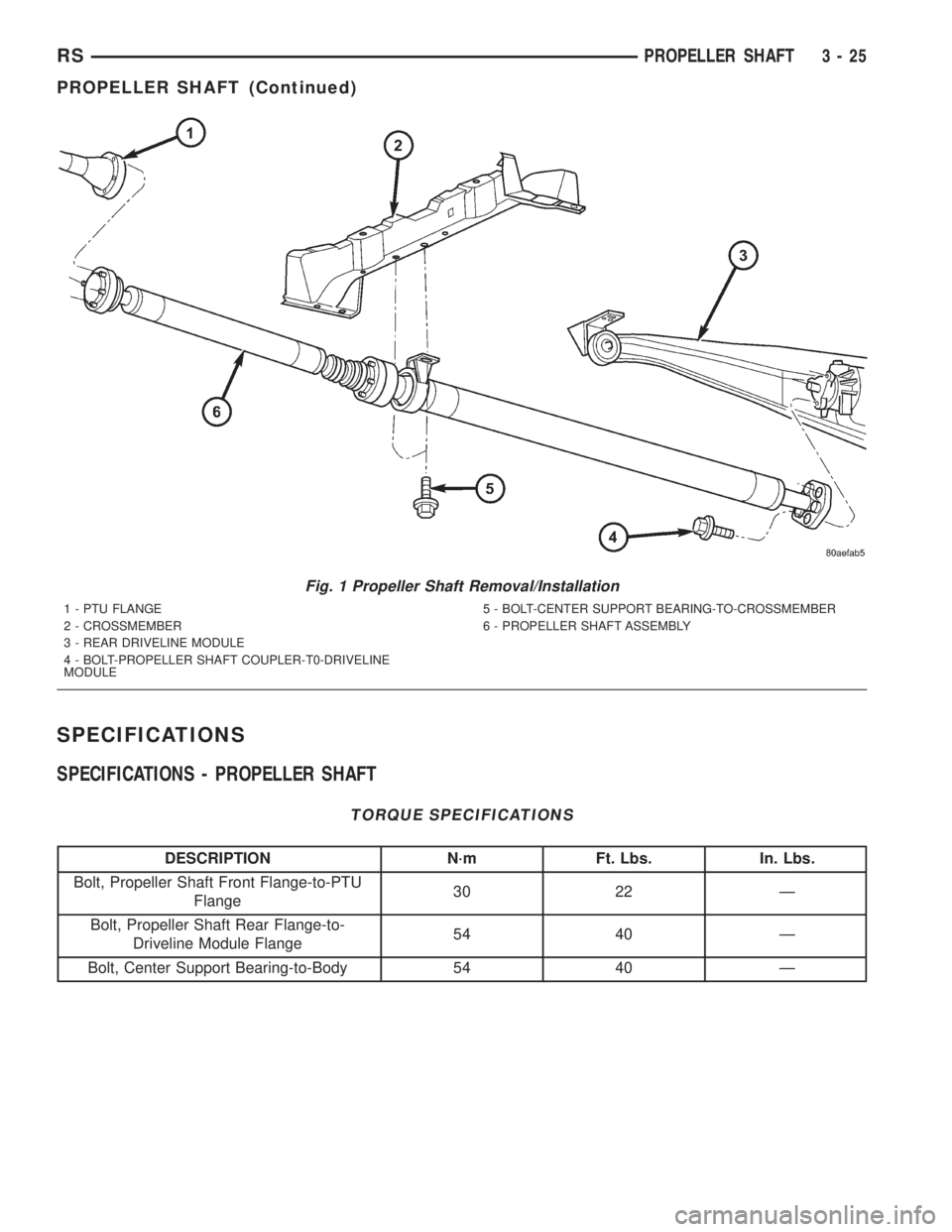
Fig. 1 Propeller Shaft Removal/Installation
1 - PTU FLANGE
2 - CROSSMEMBER
3 - REAR DRIVELINE MODULE
4 - BOLT-PROPELLER SHAFT COUPLER-T0-DRIVELINE
MODULE5 - BOLT-CENTER SUPPORT BEARING-TO-CROSSMEMBER
6 - PROPELLER SHAFT ASSEMBLY
RSPROPELLER SHAFT3-25
PROPELLER SHAFT (Continued)
Page 1602 of 4284
REAR DRIVELINE MODULE
TABLE OF CONTENTS
page page
REAR DRIVELINE MODULE
DESCRIPTION...........................26
OPERATION.............................26
DIAGNOSIS AND TESTING.................27
REAR DRIVELINE MODULE NOISE.........27
REAR DRIVELINE MODULE OPERATION....29
REMOVAL..............................29
DISASSEMBLY...........................30
ASSEMBLY.............................32
INSTALLATION...........................36
SPECIFICATIONS........................37
SPECIAL TOOLS.........................37
BI-DIRECTIONAL OVERRUNNING CLUTCH
DESCRIPTION...........................37
OPERATION.............................38
DIFFERENTIAL ASSEMBLY
DESCRIPTION...........................43
OPERATION.............................43FLUID - DIFFERENTIAL ASSEMBLY
STANDARD PROCEDURE..................44
DIFFERENTIAL ASSEMBLY FLUID CHANGE . . 44
FLUID
STANDARD PROCEDURE..................44
OVERRUNNING CLUTCH HOUSING FLUID
CHANGE..............................44
VISCOUS COUPLER
DESCRIPTION...........................45
OPERATION.............................45
TORQUE ARM
REMOVAL..............................47
INSTALLATION...........................47
INPUT FLANGE SEAL
REMOVAL..............................47
INSTALLATION...........................47
OUTPUT FLANGE SEAL
REMOVAL..............................49
INSTALLATION...........................50
REAR DRIVELINE MODULE
DESCRIPTION
The rear driveline module assembly (Fig. 1) con-
sists of four main components:
²Bi-Directional Overrunning Clutch (BOC)
²Viscous Coupling
²Differential Assembly
²Torque Arm
The viscous coupling and bi-directional overrun-
ning clutch are contained within an overrunning
clutch housing, which fastens to the differential
assembly. The overrunning clutch housing and differ-
ential assembly have unique fluid sumps, each
requiring their own type and capacity of fluid. The
overrunning clutch housing requires MopartATF+4
(Automatic Transmission FluidÐType 9602) or equiv-
alent. The differential assembly requires
Driveline module service is limited to the following
components:
²Differential Assembly (serviced only as assem-
bly)
²Viscous Coupling
²Bi-Directional Overrunning Clutch (BOC)
²Overrunning Clutch Housing
²Seals (Input Flange, Output Flange, Overrun-
ning Clutch Housing O-rings)
²Input Flange/Shield²Torque Arm
²Vents
²FastenersOPERATION
The primary benefits of All Wheel Drive are:
²Superior straight line acceleration, and corner-
ing on all surfaces
²Better traction and handling under adverse con-
ditions, resulting in improved hill climbing ability
and safer driving.
The heart of the system is an inter-axle viscous
coupling. The vehicle retains predominantly front-
wheel drive characteristics, but the All Wheel Drive
capability takes effect when the front wheels start to
slip. Under normal level road, straight line driving,
100% of the torque is allocated to the front wheels.
The viscous coupling controls and distributes torque/
power to the rear wheels. The viscous coupling trans-
mits torque to the rear wheels in proportion of the
amount of the slippage at the front wheels. Thais
variable torque distribution is automatic with no
driver inputs required. The coupling is similar to a
multi-plate clutch. It consists of a series of closely
spaced discs, which are alternately connected to the
front and rear drive units. The unit is totally sealed
and partially filled with silicone fluid. There is no
3 - 26 REAR DRIVELINE MODULERS
Page 1603 of 4284
adjustment, maintenance or fluid checks required
during the life of the unit.
The overrunning clutch allows the rear wheels to
overrun the front wheels during a rapid front wheel
lock braking maneuver. The overrunning action pre-
vents any feed-back of front wheel braking torque to
the rear wheels. It also allows the braking system to
control the braking behavior as a two wheel drive
(2WD) vehicle.
The overrunning clutch housing has a separate oil
sump and is filled independently from the differen-
tial. The fill plug is located on the side of the over-
running clutch case. When filling the overrunning
clutch with lubricant use MopartATF+4 (Automatic
Transmission FluidÐType 9602) or equivalent.
The differential assembly contains a conventional
open differential with hypoid ring gear and pinion
gear set. The hypoid gears are lubricated by SAE
80W-90 gear lubricant.DIAGNOSIS AND TESTING - REAR DRIVELINE
MODULE NOISE
Different sources can be the cause of noise that the
rear driveline module assembly is suspected of mak-
ing. Refer to the following causes for noise diagnosis.
DRIVELINE MODULE ASSEMBLY NOISE
The most important part of driveline module ser-
vice is properly identifying the cause of failures and
noise complaints. The cause of most driveline module
failures is relatively easy to identify. The cause of
driveline module noise is more difficult to identify.
If vehicle noise becomes intolerable, an effort
should be made to isolate the noise. Many noises that
are reported as coming from the driveline module
may actually originate at other sources. For example:
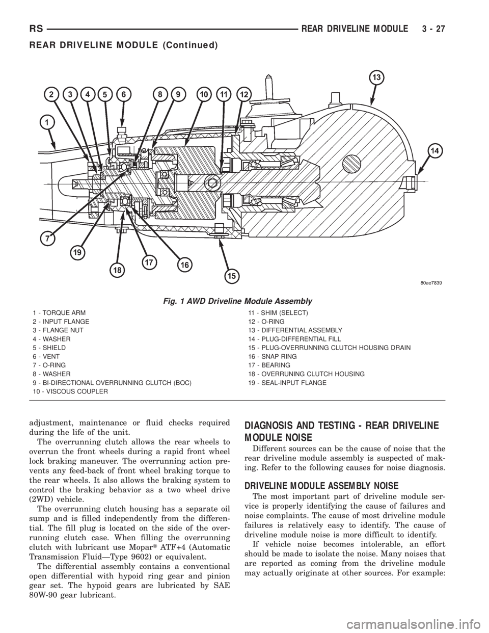
Fig. 1 AWD Driveline Module Assembly
1 - TORQUE ARM
2 - INPUT FLANGE
3 - FLANGE NUT
4 - WASHER
5 - SHIELD
6 - VENT
7 - O-RING
8 - WASHER
9 - BI-DIRECTIONAL OVERRUNNING CLUTCH (BOC)
10 - VISCOUS COUPLER11 - SHIM (SELECT)
12 - O-RING
13 - DIFFERENTIAL ASSEMBLY
14 - PLUG-DIFFERENTIAL FILL
15 - PLUG-OVERRUNNING CLUTCH HOUSING DRAIN
16 - SNAP RING
17 - BEARING
18 - OVERRUNING CLUTCH HOUSING
19 - SEAL-INPUT FLANGE
RSREAR DRIVELINE MODULE3-27
REAR DRIVELINE MODULE (Continued)
Page 1605 of 4284
DIAGNOSIS AND TESTING - REAR DRIVELINE
MODULE OPERATION
Driveline module operation requires relatively
straight-forward diagnosis. Refer to the following
chart:
DRIVELINE MODULE DIAGNOSIS CHART
CONDITION POSSIBLE CAUSES CORRECTION
Rear wheels not
overrunning1) Bi-directional overrunning clutch
failure1) Replace overrunning clutch
components as required
No AWD in forward or
reverse directions, propeller
shaft turning1) Bi-directional overrunning clutch
failure1) Replace overrunning clutch
components as required
2) Viscous coupling failure 2) Replace viscous coupling
3) Rear differential failure 3) Replace the rear differential
assembly
No AWD in forward or
reverse directions, propeller
shaft not turning1) Power transfer unit failure. 1) Replace power transfer unit
components as necessary
Vibration at all speeds,
continuous torque transfer1) Mis-matched tires, worn tires on
front axle.1) Replace worn or incorrect
(mis-matched) tires with same
make and size
REMOVAL
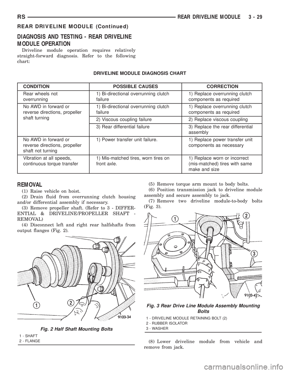
(1) Raise vehicle on hoist.
(2) Drain fluid from overrunning clutch housing
and/or differential assembly if necessary.
(3) Remove propeller shaft. (Refer to 3 - DIFFER-
ENTIAL & DRIVELINE/PROPELLER SHAFT -
REMOVAL)
(4) Disconnect left and right rear halfshafts from
output flanges (Fig. 2).(5) Remove torque arm mount to body bolts.
(6) Position transmission jack to driveline module
assembly and secure assembly to jack.
(7) Remove two driveline module-to-body bolts
(Fig. 3).
(8) Lower driveline module from vehicle and
remove from jack.
Fig. 2 Half Shaft Mounting Bolts
1 - SHAFT
2 - FLANGE
Fig. 3 Rear Drive Line Module Assembly Mounting
Bolts
1 - DRIVELINE MODULE RETAINING BOLT (2)
2 - RUBBER ISOLATOR
3 - WASHER
RSREAR DRIVELINE MODULE3-29
REAR DRIVELINE MODULE (Continued)
Page 1606 of 4284
DISASSEMBLY
WARNING: Differential is only to be serviced as an
assembly, and no disassembly is required.
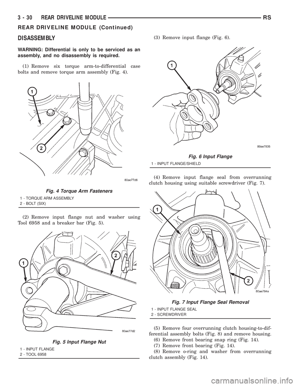
(1) Remove six torque arm-to-differential case
bolts and remove torque arm assembly (Fig. 4).
(2) Remove input flange nut and washer using
Tool 6958 and a breaker bar (Fig. 5).(3) Remove input flange (Fig. 6).
(4) Remove input flange seal from overrunning
clutch housing using suitable screwdriver (Fig. 7).
(5) Remove four overrunning clutch housing-to-dif-
ferential assembly bolts (Fig. 8) and remove housing.
(6) Remove front bearing snap ring (Fig. 14).
(7) Remove front bearing (Fig. 14).
(8) Remove o-ring and washer from overrunning
clutch assembly (Fig. 14).
Fig. 4 Torque Arm Fasteners
1 - TORQUE ARM ASSEMBLY
2 - BOLT (SIX)
Fig. 5 Input Flange Nut
1 - INPUT FLANGE
2 - TOOL 6958
Fig. 6 Input Flange
1 - INPUT FLANGE/SHIELD
Fig. 7 Input Flange Seal Removal
1 - INPUT FLANGE SEAL
2 - SCREWDRIVER
3 - 30 REAR DRIVELINE MODULERS
REAR DRIVELINE MODULE (Continued)
Page 1608 of 4284
ASSEMBLY
(1) Install output flange seals using tools C4171
and 8493 (Fig. 15).
(2) Install large overrunning clutch housing o-ring
to differential assembly (Fig. 14).
(3) Install shim to differential pinion shaft (Fig.
16).
(4) Install viscous coupler to differential pinion
shaft (Fig. 17).
(5) Install overrunning clutch assembly to viscous
coupler (Fig. 18).
(6) Install washer to overrunning clutch (Fig. 14).
(7) Install o-ring to overrunning clutch (Fig. 14).
(8) Align overrunning clutch ground tab to 12
o'clock position (Fig. 19).
(9) Install overrunning clutch housing into posi-
tion, making sure ground tab engages with notch in
housing (Fig. 20).
(10) Install and torque overrunning clutch hous-
ing-to-differential assembly bolts (Fig. 21) to 60 N´m
(44 ft. lbs.).
(11) Install input flange seal using tool 8802 (Fig.
22).
(12) Install flange/shield assembly (Fig. 23).
(13) Install input flange washer and nut. Using
tool 6958 (Fig. 24), torque nut to 135 N´m (100 ft.
lbs.).
(14) Install torque arm assembly into position.
Install and torque torque arm-to-differential assem-
bly bolts (Fig. 25) to 60 N´m (44 ft. lbs.).
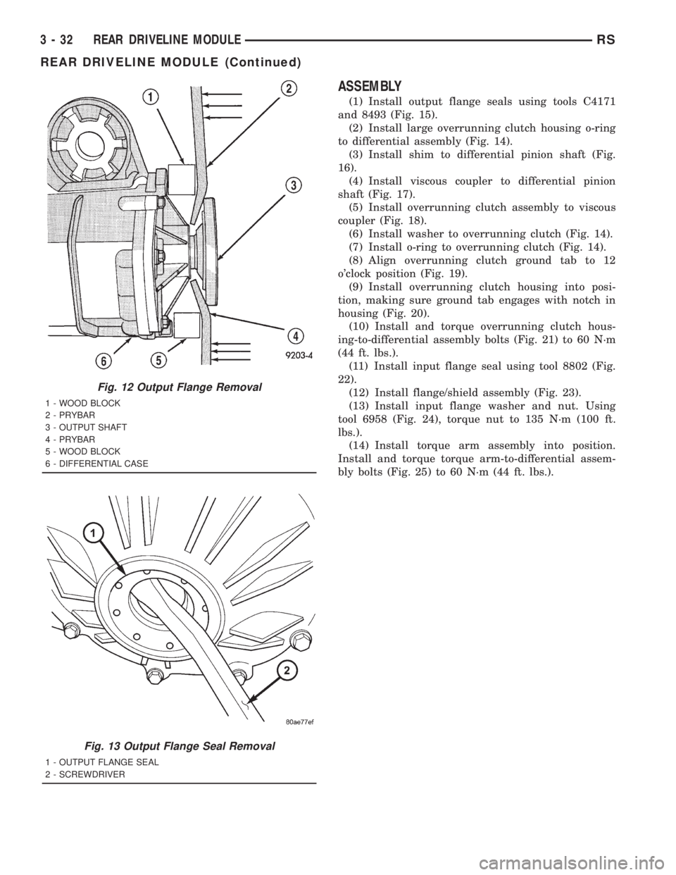
Fig. 12 Output Flange Removal
1 - WOOD BLOCK
2 - PRYBAR
3 - OUTPUT SHAFT
4 - PRYBAR
5 - WOOD BLOCK
6 - DIFFERENTIAL CASE
Fig. 13 Output Flange Seal Removal
1 - OUTPUT FLANGE SEAL
2 - SCREWDRIVER
3 - 32 REAR DRIVELINE MODULERS
REAR DRIVELINE MODULE (Continued)
Page 1612 of 4284
INSTALLATION
(1) Install rear driveline module assembly to
transmission jack and secure.
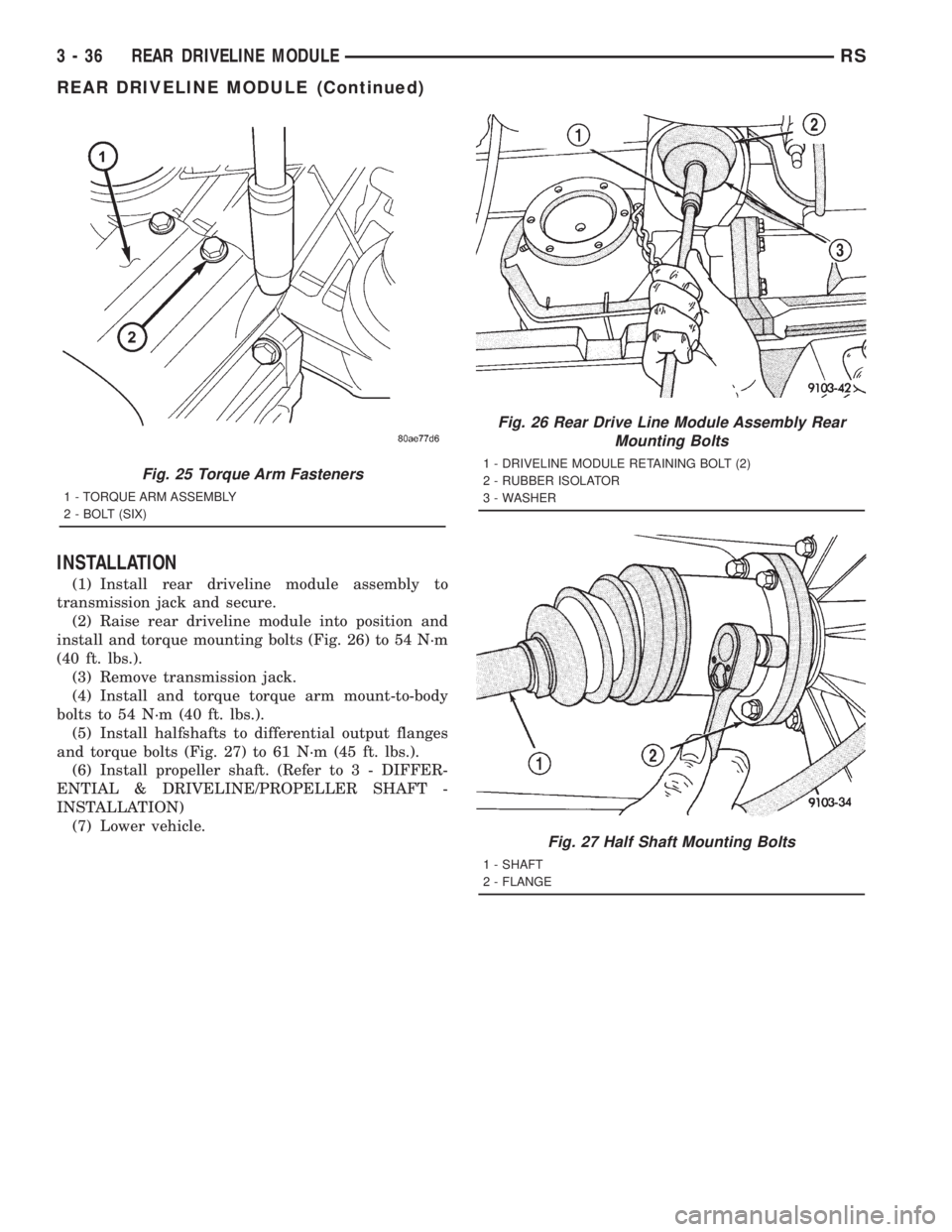
(2) Raise rear driveline module into position and
install and torque mounting bolts (Fig. 26) to 54 N´m
(40 ft. lbs.).
(3) Remove transmission jack.
(4) Install and torque torque arm mount-to-body
bolts to 54 N´m (40 ft. lbs.).
(5) Install halfshafts to differential output flanges
and torque bolts (Fig. 27) to 61 N´m (45 ft. lbs.).
(6) Install propeller shaft. (Refer to 3 - DIFFER-
ENTIAL & DRIVELINE/PROPELLER SHAFT -
INSTALLATION)
(7) Lower vehicle.
Fig. 25 Torque Arm Fasteners
1 - TORQUE ARM ASSEMBLY
2 - BOLT (SIX)
Fig. 26 Rear Drive Line Module Assembly Rear
Mounting Bolts
1 - DRIVELINE MODULE RETAINING BOLT (2)
2 - RUBBER ISOLATOR
3 - WASHER
Fig. 27 Half Shaft Mounting Bolts
1 - SHAFT
2 - FLANGE
3 - 36 REAR DRIVELINE MODULERS
REAR DRIVELINE MODULE (Continued)
Page 1613 of 4284
SPECIFICATIONS
SPECIFICATIONS - REAR DRIVELINE MODULE
TORQUE SPECIFICATIONS
DESCRIPTION N´m Ft. Lbs. In. Lbs.
Bolt, Driveline Module-to-Body 54 40 Ð
Bolt, Halfshaft-to-Ouput Flange 61 45 Ð
Bolt, Overrunning Clutch Housing-to-
Differential60 44 Ð
Bolt, Torque Arm-to-Differential Assembly 60 44 Ð
Bolt, Torque Arm Mount-to-Body 54 40 Ð
Nut, Input Flange 135 100 Ð
Plug, Differential Drain/Fill 35 26 Ð
Plug, Overrunning Clutch Housing Drain/Fill 30 22 Ð
Vent, Differential/Overrunning Clutch
Housing12 Ð 110
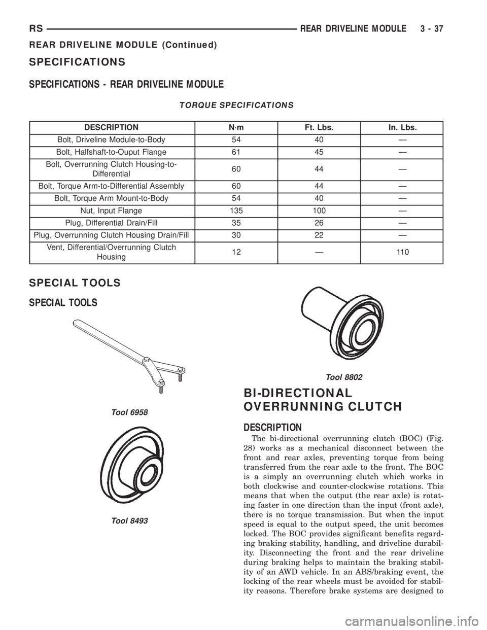
SPECIAL TOOLS
SPECIAL TOOLS
BI-DIRECTIONAL
OVERRUNNING CLUTCH
DESCRIPTION
The bi-directional overrunning clutch (BOC) (Fig.
28) works as a mechanical disconnect between the
front and rear axles, preventing torque from being
transferred from the rear axle to the front. The BOC
is a simply an overrunning clutch which works in
both clockwise and counter-clockwise rotations. This
means that when the output (the rear axle) is rotat-
ing faster in one direction than the input (front axle),
there is no torque transmission. But when the input
speed is equal to the output speed, the unit becomes
locked. The BOC provides significant benefits regard-
ing braking stability, handling, and driveline durabil-
ity. Disconnecting the front and the rear driveline
during braking helps to maintain the braking stabil-
ity of an AWD vehicle. In an ABS/braking event, the
locking of the rear wheels must be avoided for stabil-
ity reasons. Therefore brake systems are designed to
Tool 6958
Tool 8493
Tool 8802
RSREAR DRIVELINE MODULE3-37
REAR DRIVELINE MODULE (Continued)