check engine CHRYSLER VOYAGER 2001 Service Manual
[x] Cancel search | Manufacturer: CHRYSLER, Model Year: 2001, Model line: VOYAGER, Model: CHRYSLER VOYAGER 2001Pages: 4284, PDF Size: 83.53 MB
Page 1890 of 4284
Spiral plate technology is the process by which the
plates holding the active material in the battery are
wound tightly in coils instead of hanging flat, like
conventional batteries. This design has a lower inter-
nal resistance and also increases the active material
surface area.
WARNING: NEVER EXCEED 14.4 VOLTS WHEN
CHARGING A SPIRAL PLATE BATTERY. PERSONAL
INJURY AND/OR BATTERY DAMAGE MAY RESULT.
Due to the maintanance-free design, distilled water
cannot be added to this battery. Therefore, if more
than 14.4 volts are used during the spiral plate bat-
tery charging process, water vapor can be exhausted
through the pressure-sensitive battery vents and lost
for good. This can permanently damage the spiral
plate battery. Never exceed 14.4 volts when charging
a spiral plate battery. Personal injury and/or battery
damage may result.
CONVENTIONAL BATTERY - GASOLINE ENGINE
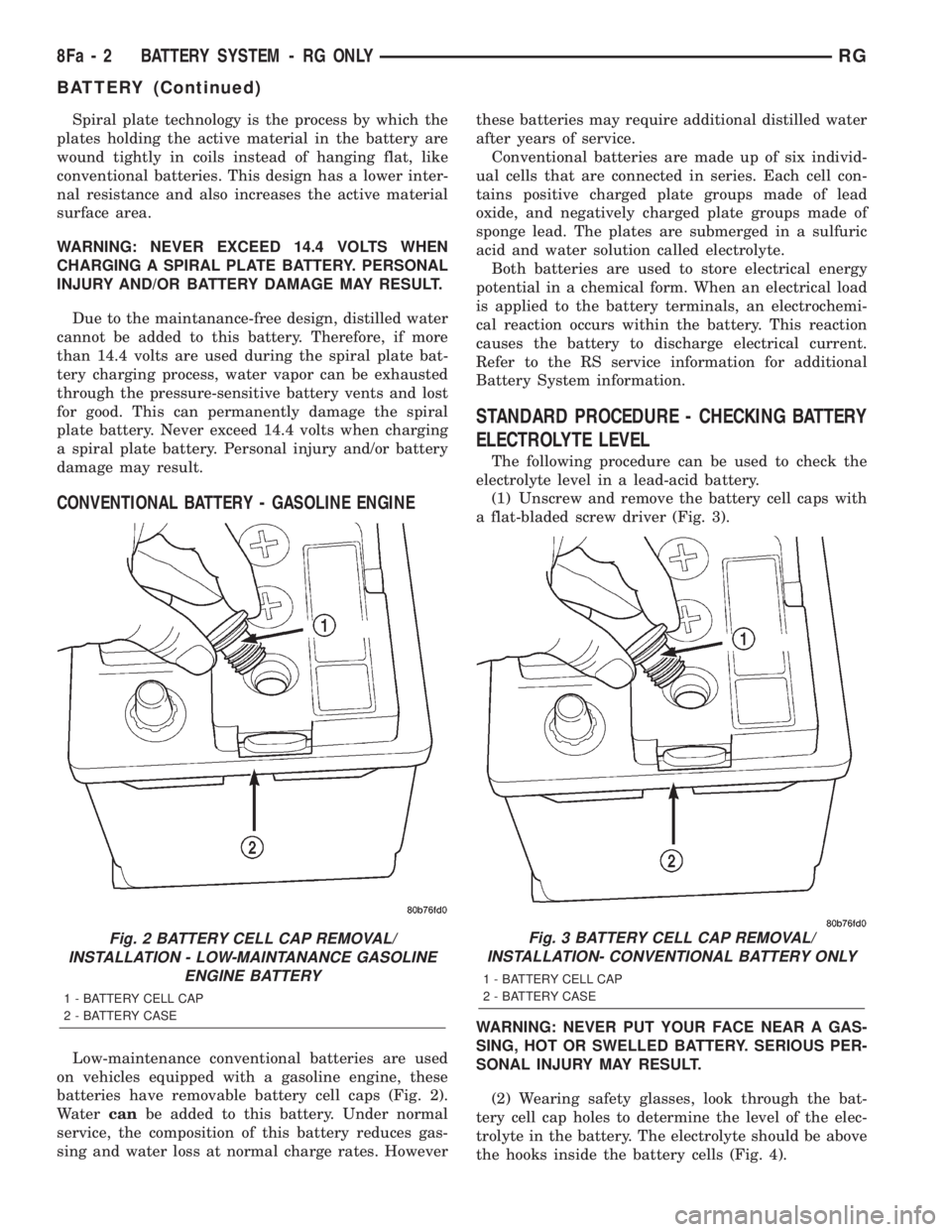
Low-maintenance conventional batteries are used
on vehicles equipped with a gasoline engine, these
batteries have removable battery cell caps (Fig. 2).
Watercanbe added to this battery. Under normal
service, the composition of this battery reduces gas-
sing and water loss at normal charge rates. Howeverthese batteries may require additional distilled water
after years of service.
Conventional batteries are made up of six individ-
ual cells that are connected in series. Each cell con-
tains positive charged plate groups made of lead
oxide, and negatively charged plate groups made of
sponge lead. The plates are submerged in a sulfuric
acid and water solution called electrolyte.
Both batteries are used to store electrical energy
potential in a chemical form. When an electrical load
is applied to the battery terminals, an electrochemi-
cal reaction occurs within the battery. This reaction
causes the battery to discharge electrical current.
Refer to the RS service information for additional
Battery System information.
STANDARD PROCEDURE - CHECKING BATTERY
ELECTROLYTE LEVEL
The following procedure can be used to check the
electrolyte level in a lead-acid battery.
(1) Unscrew and remove the battery cell caps with
a flat-bladed screw driver (Fig. 3).
WARNING: NEVER PUT YOUR FACE NEAR A GAS-
SING, HOT OR SWELLED BATTERY. SERIOUS PER-
SONAL INJURY MAY RESULT.
(2) Wearing safety glasses, look through the bat-
tery cell cap holes to determine the level of the elec-
trolyte in the battery. The electrolyte should be above
the hooks inside the battery cells (Fig. 4).
Fig. 2 BATTERY CELL CAP REMOVAL/
INSTALLATION - LOW-MAINTANANCE GASOLINE
ENGINE BATTERY
1 - BATTERY CELL CAP
2 - BATTERY CASE
Fig. 3 BATTERY CELL CAP REMOVAL/
INSTALLATION- CONVENTIONAL BATTERY ONLY
1 - BATTERY CELL CAP
2 - BATTERY CASE
8Fa - 2 BATTERY SYSTEM - RG ONLYRG
BATTERY (Continued)
Page 1901 of 4284
HEATED MIRRORS
TABLE OF CONTENTS
page page
HEATED MIRRORS
DESCRIPTION............................5
OPERATION.............................5
DIAGNOSIS AND TESTING..................5
HEATED MIRROR TEST...................5
MIRROR SWITCH
DESCRIPTION............................5OPERATION.............................5
HEATED MIRROR GRID
STANDARD PROCEDURE...................6
HEATED MIRROR.......................6
RELAY
DESCRIPTION............................6
HEATED MIRRORS
DESCRIPTION
Heated mirrors are available on models with
Power Mirrors and Rear Window Defogger only.
OPERATION
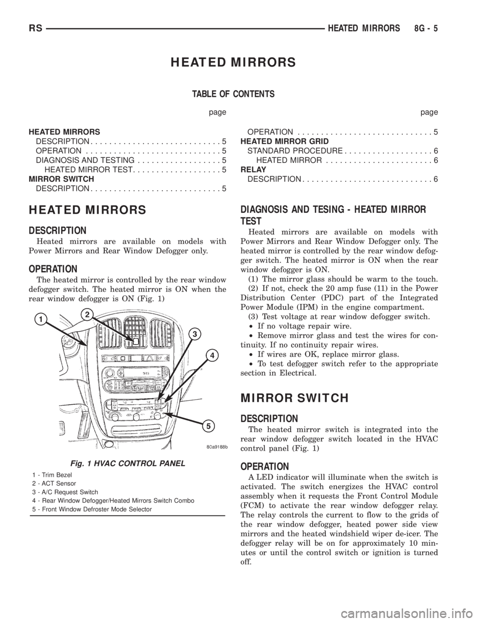
The heated mirror is controlled by the rear window
defogger switch. The heated mirror is ON when the
rear window defogger is ON (Fig. 1)
DIAGNOSIS AND TESING - HEATED MIRROR
TEST
Heated mirrors are available on models with
Power Mirrors and Rear Window Defogger only. The
heated mirror is controlled by the rear window defog-
ger switch. The heated mirror is ON when the rear
window defogger is ON.
(1) The mirror glass should be warm to the touch.
(2) If not, check the 20 amp fuse (11) in the Power
Distribution Center (PDC) part of the Integrated
Power Module (IPM) in the engine compartment.
(3) Test voltage at rear window defogger switch.
²If no voltage repair wire.
²Remove mirror glass and test the wires for con-
tinuity. If no continuity repair wires.
²If wires are OK, replace mirror glass.
²To test defogger switch refer to the appropriate
section in Electrical.
MIRROR SWITCH
DESCRIPTION
The heated mirror switch is integrated into the
rear window defogger switch located in the HVAC
control panel (Fig. 1)
OPERATION
A LED indicator will illuminate when the switch is
activated. The switch energizes the HVAC control
assembly when it requests the Front Control Module
(FCM) to activate the rear window defogger relay.
The relay controls the current to flow to the grids of
the rear window defogger, heated power side view
mirrors and the heated windshield wiper de-icer. The
defogger relay will be on for approximately 10 min-
utes or until the control switch or ignition is turned
off.
Fig. 1 HVAC CONTROL PANEL
1 - Trim Bezel
2 - ACT Sensor
3 - A/C Request Switch
4 - Rear Window Defogger/Heated Mirrors Switch Combo
5 - Front Window Defroster Mode Selector
RSHEATED MIRRORS8G-5
Page 1911 of 4284
HORN
TABLE OF CONTENTS
page page
HORN
DESCRIPTION............................1
OPERATION.............................1
DIAGNOSIS AND TESTING..................1
HORN
DIAGNOSIS AND TESTING..................3
REMOVAL...............................4INSTALLATION............................5
HORN RELAY
DIAGNOSIS AND TESTING..................5
REMOVAL...............................5
INSTALLATION............................5
HORN SWITCH
DESCRIPTION............................5
HORN
DESCRIPTION
HORN SYSTEM
WARNING:
ON VEHICLES EQUIPPED WITH AIRBAG, REFER TO
ELECTRICAL, RESTRAINTS FOR SAFETY PRECAU-
TIONS. DISCONNECT THE NEGATIVE CABLE FROM
THE BATTERY BEFORE SERVICING COMPONENTS
INVOLVING THE AIRBAG SYSTEM. ACCIDENTAL
DEPLOYMENT OF AIRBAG AND PERSONAL INJURY
CAN RESULT.
The horn circuit consists of a horn switch, clock-
spring, horn relay, horns and intelligent power mod-
ule. The horn switch is a membrane switch located in
the airbag trim cover. The horns are located forward
of the left front wheel behind the bumper fascia.
OPERATION
The horn relay plugs into the intelligent power
module which is located in the engine compartment.
For circuit information and component locations,
refer to the appropriate wiring information. The wir-
ing information includes wiring diagrams, proper
wire and connector repair procedures, details of wire
harness routing and retention, connector pin-out
information and location views for the various wire
harness connectors, splices and grounds.
The horns will not function if the switch is
ªCLOSEDº for more than 30 seconds. Once the
switch is ªOPENº, a 20±30 second delay will occur
before the horns are functional again.
DIAGNOSIS AND TESTING
Refer to Horn System Test below. If the horn does
not sound, check horn fuse located in the intelligent
power module. If the fuse is blown, replace with the
correct fuse. If the horns fail to sound and the new
fuse blows when depressing the horn switch, a short
circuit in the horn or the horn wiring between the
fuse terminal and the horn is responsible, or a defec-
tive horn switch allowed the horn to burn out is
responsible.
If the fuse is OK, test horn relay (Refer to 8 -
ELECTRICAL/HORN/HORN RELAY - DIAGNOSIS
AND TESTING).
If the relay is OK, test horn. Refer to Horn System
Test.
CAUTION:
Continuous sounding of horn may cause horn relay
to fail.
Should the horn sound continuously:
²Unplug the horn relay from intelligent power
module.
²Refer to (Refer to 8 - ELECTRICAL/HORN/
HORN RELAY - DIAGNOSIS AND TESTING).
Refer to the appropriate wiring information. The
wiring information includes wiring diagrams, proper
wire and connector repair procedures, details of wire
harness routing and retention, connector pin-out
information and location views for the various wire
harness connectors, splices and grounds.
RSHORN8H-1
Page 1919 of 4284
AUTO SHUT DOWN RELAY
DESCRIPTION
The relay is located in the Power Distribution Cen-
ter (PDC). For the location of the relay within the
PDC, refer to the PDC cover for location. Check elec-
trical terminals for corrosion and repair as necessary
OPERATION
The ASD sense circuit informs the PCM when the
ASD relay energizes. A 12 volt signal at this input
indicates to the PCM that the ASD has been acti-
vated. This input is used only to sense that the ASD
relay is energized.
When energized, the ASD relay supplies battery
voltage to the fuel injectors, ignition coils and the
heating element in each oxygen sensor. If the PCM
does not receive 12 volts from this input after
grounding the ASD relay, it sets a Diagnostic Trouble
Code (DTC).
When energized, the ASD relay provides power to
operate the injectors, ignition coil, generator field, O2
sensor heaters (both upstream and downstream), and
also provides a sense circuit to the PCM for diagnos-
tic purposes. The PCM energizes the ASD any time
there is a Crankshaft Position sensor signal that
exceeds a predetermined value. The ASD relay can
also be energized after the engine has been turned
off to perform an O2 sensor heater test, if vehicle is
equipped with OBD II diagnostics.
As mentioned earlier, the PCM energizes the ASD
relay during an O2 sensor heater test. This test is
performed only after the engine has been shut off.
The PCM still operates internally to perform several
checks, including monitoring the O2 sensor heaters.
CAMSHAFT POSITION
SENSOR
DESCRIPTION
The camshaft position sensorfor the 3.3/3.8L is
mounted in the front of the timing case cover (Fig. 7)
and the camshaft position sensor for the 2.4L is
mounted on the end of the cylinder head (Fig. 4).
OPERATION
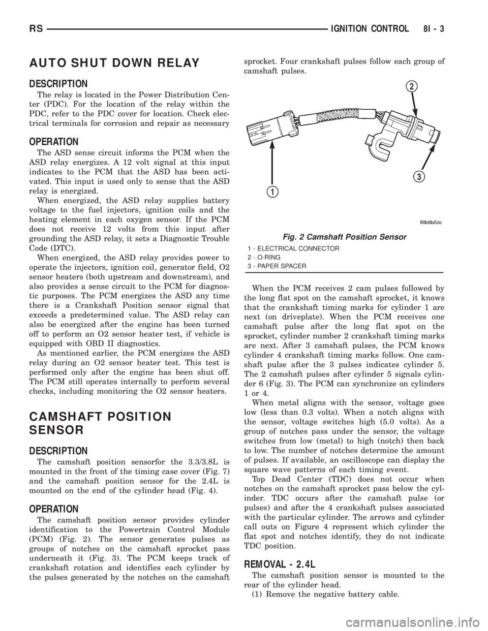
The camshaft position sensor provides cylinder
identification to the Powertrain Control Module
(PCM) (Fig. 2). The sensor generates pulses as
groups of notches on the camshaft sprocket pass
underneath it (Fig. 3). The PCM keeps track of
crankshaft rotation and identifies each cylinder by
the pulses generated by the notches on the camshaftsprocket. Four crankshaft pulses follow each group of
camshaft pulses.
When the PCM receives 2 cam pulses followed by
the long flat spot on the camshaft sprocket, it knows
that the crankshaft timing marks for cylinder 1 are
next (on driveplate). When the PCM receives one
camshaft pulse after the long flat spot on the
sprocket, cylinder number 2 crankshaft timing marks
are next. After 3 camshaft pulses, the PCM knows
cylinder 4 crankshaft timing marks follow. One cam-
shaft pulse after the 3 pulses indicates cylinder 5.
The 2 camshaft pulses after cylinder 5 signals cylin-
der 6 (Fig. 3). The PCM can synchronize on cylinders
1or4.
When metal aligns with the sensor, voltage goes
low (less than 0.3 volts). When a notch aligns with
the sensor, voltage switches high (5.0 volts). As a
group of notches pass under the sensor, the voltage
switches from low (metal) to high (notch) then back
to low. The number of notches determine the amount
of pulses. If available, an oscilloscope can display the
square wave patterns of each timing event.
Top Dead Center (TDC) does not occur when
notches on the camshaft sprocket pass below the cyl-
inder. TDC occurs after the camshaft pulse (or
pulses) and after the 4 crankshaft pulses associated
with the particular cylinder. The arrows and cylinder
call outs on Figure 4 represent which cylinder the
flat spot and notches identify, they do not indicate
TDC position.
REMOVAL - 2.4L
The camshaft position sensor is mounted to the
rear of the cylinder head.
(1) Remove the negative battery cable.
Fig. 2 Camshaft Position Sensor
1 - ELECTRICAL CONNECTOR
2 - O-RING
3 - PAPER SPACER
RSIGNITION CONTROL8I-3
Page 1924 of 4284
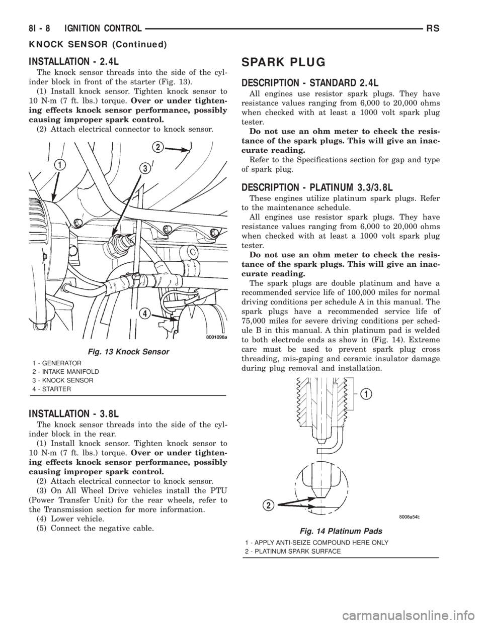
INSTALLATION - 2.4L
The knock sensor threads into the side of the cyl-
inder block in front of the starter (Fig. 13).
(1) Install knock sensor. Tighten knock sensor to
10 N´m (7 ft. lbs.) torque.Over or under tighten-
ing effects knock sensor performance, possibly
causing improper spark control.
(2) Attach electrical connector to knock sensor.
INSTALLATION - 3.8L
The knock sensor threads into the side of the cyl-
inder block in the rear.
(1) Install knock sensor. Tighten knock sensor to
10 N´m (7 ft. lbs.) torque.Over or under tighten-
ing effects knock sensor performance, possibly
causing improper spark control.
(2) Attach electrical connector to knock sensor.
(3) On All Wheel Drive vehicles install the PTU
(Power Transfer Unit) for the rear wheels, refer to
the Transmission section for more information.
(4) Lower vehicle.
(5) Connect the negative cable.
SPARK PLUG
DESCRIPTION - STANDARD 2.4L
All engines use resistor spark plugs. They have
resistance values ranging from 6,000 to 20,000 ohms
when checked with at least a 1000 volt spark plug
tester.
Do not use an ohm meter to check the resis-
tance of the spark plugs. This will give an inac-
curate reading.
Refer to the Specifications section for gap and type
of spark plug.
DESCRIPTION - PLATINUM 3.3/3.8L
These engines utilize platinum spark plugs. Refer
to the maintenance schedule.
All engines use resistor spark plugs. They have
resistance values ranging from 6,000 to 20,000 ohms
when checked with at least a 1000 volt spark plug
tester.
Do not use an ohm meter to check the resis-
tance of the spark plugs. This will give an inac-
curate reading.
The spark plugs are double platinum and have a
recommended service life of 100,000 miles for normal
driving conditions per schedule A in this manual. The
spark plugs have a recommended service life of
75,000 miles for severe driving conditions per sched-
ule B in this manual. A thin platinum pad is welded
to both electrode ends as show in (Fig. 14). Extreme
care must be used to prevent spark plug cross
threading, mis-gaping and ceramic insulator damage
during plug removal and installation.
Fig. 13 Knock Sensor
1 - GENERATOR
2 - INTAKE MANIFOLD
3 - KNOCK SENSOR
4-STARTER
Fig. 14 Platinum Pads
1 - APPLY ANTI-SEIZE COMPOUND HERE ONLY
2 - PLATINUM SPARK SURFACE
8I - 8 IGNITION CONTROLRS
KNOCK SENSOR (Continued)
Page 1927 of 4284
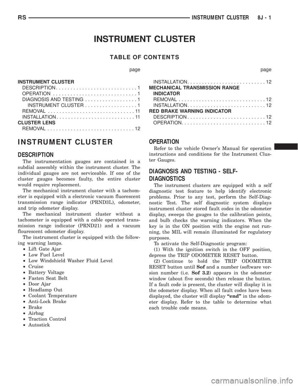
INSTRUMENT CLUSTER
TABLE OF CONTENTS
page page
INSTRUMENT CLUSTER
DESCRIPTION............................1
OPERATION.............................1
DIAGNOSIS AND TESTING..................1
INSTRUMENT CLUSTER..................1
REMOVAL..............................11
INSTALLATION...........................11
CLUSTER LENS
REMOVAL..............................12INSTALLATION...........................12
MECHANICAL TRANSMISSION RANGE
INDICATOR
REMOVAL..............................12
INSTALLATION...........................12
RED BRAKE WARNING INDICATOR
DESCRIPTION...........................12
OPERATION.............................12
INSTRUMENT CLUSTER
DESCRIPTION
The instrumentation gauges are contained in a
subdial assembly within the instrument cluster. The
individual gauges are not serviceable. If one of the
cluster gauges becomes faulty, the entire cluster
would require replacement.
The mechanical instrument cluster with a tachom-
eter is equipped with a electronic vacuum fluorescent
transmission range indicator (PRND3L), odometer,
and trip odometer display.
The mechanical instrument cluster without a
tachometer is equipped with a cable operated trans-
mission range indicator (PRND21) and a vacuum
flourescent odometer display.
The instrument cluster is equipped with the follow-
ing warning lamps.
²Lift Gate Ajar
²Low Fuel Level
²Low Windshield Washer Fluid Level
²Cruise
²Battery Voltage
²Fasten Seat Belt
²Door Ajar
²Headlamp Out
²Coolant Temperature
²Anti-Lock Brake
²Brake
²Airbag
²Traction Control
²Autostick
OPERATION
Refer to the vehicle Owner's Manual for operation
instructions and conditions for the Instrument Clus-
ter Gauges.
DIAGNOSIS AND TESTING - SELF-
DIAGNOSTICS
The instrument clusters are equipped with a self
diagnostic test feature to help identify electronic
problems. Prior to any test, perform the Self-Diag-
nostic Test. The self diagnostic system displays
instrument cluster stored fault codes in the odometer
display, sweeps the gauges to the calibration points,
and bulb checks the warning indicators. When the
key is in the ON position with the engine not run-
ning, the MIL will remain illuminated for regulatory
purposes.
To activate the Self-Diagnostic program:
(1) With the ignition switch in the OFF position,
depress the TRIP ODOMETER RESET button.
(2) Continue to hold the TRIP ODOMETER
RESET button untilSofand a number (software ver-
sion number (i.e.Sof 3.2) appears in the odometer
window (about five seconds) then release the button.
If a fault code is present, the cluster will display it in
the odometer display. When all fault codes have been
displayed, the cluster will displayªendºin the odom-
eter display. Refer to the table to determine what
each trouble code means.
RSINSTRUMENT CLUSTER8J-1
Page 1930 of 4284
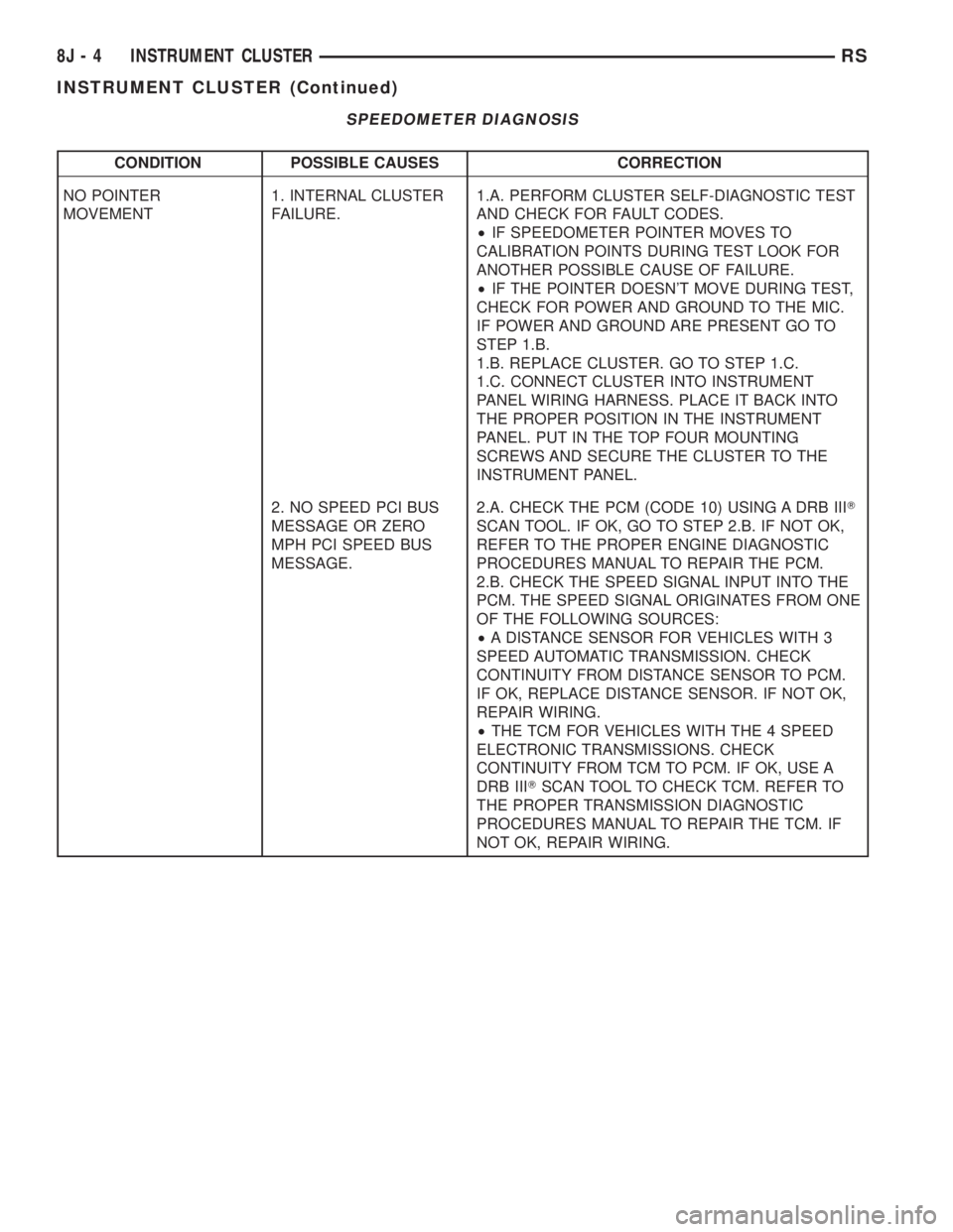
SPEEDOMETER DIAGNOSIS
CONDITION POSSIBLE CAUSES CORRECTION
NO POINTER
MOVEMENT1. INTERNAL CLUSTER
FAILURE.1.A. PERFORM CLUSTER SELF-DIAGNOSTIC TEST
AND CHECK FOR FAULT CODES.
²IF SPEEDOMETER POINTER MOVES TO
CALIBRATION POINTS DURING TEST LOOK FOR
ANOTHER POSSIBLE CAUSE OF FAILURE.
²IF THE POINTER DOESN'T MOVE DURING TEST,
CHECK FOR POWER AND GROUND TO THE MIC.
IF POWER AND GROUND ARE PRESENT GO TO
STEP 1.B.
1.B. REPLACE CLUSTER. GO TO STEP 1.C.
1.C. CONNECT CLUSTER INTO INSTRUMENT
PANEL WIRING HARNESS. PLACE IT BACK INTO
THE PROPER POSITION IN THE INSTRUMENT
PANEL. PUT IN THE TOP FOUR MOUNTING
SCREWS AND SECURE THE CLUSTER TO THE
INSTRUMENT PANEL.
2. NO SPEED PCI BUS
MESSAGE OR ZERO
MPH PCI SPEED BUS
MESSAGE.2.A. CHECK THE PCM (CODE 10) USING A DRB IIIT
SCAN TOOL. IF OK, GO TO STEP 2.B. IF NOT OK,
REFER TO THE PROPER ENGINE DIAGNOSTIC
PROCEDURES MANUAL TO REPAIR THE PCM.
2.B. CHECK THE SPEED SIGNAL INPUT INTO THE
PCM. THE SPEED SIGNAL ORIGINATES FROM ONE
OF THE FOLLOWING SOURCES:
²A DISTANCE SENSOR FOR VEHICLES WITH 3
SPEED AUTOMATIC TRANSMISSION. CHECK
CONTINUITY FROM DISTANCE SENSOR TO PCM.
IF OK, REPLACE DISTANCE SENSOR. IF NOT OK,
REPAIR WIRING.
²THE TCM FOR VEHICLES WITH THE 4 SPEED
ELECTRONIC TRANSMISSIONS. CHECK
CONTINUITY FROM TCM TO PCM. IF OK, USE A
DRB IIITSCAN TOOL TO CHECK TCM. REFER TO
THE PROPER TRANSMISSION DIAGNOSTIC
PROCEDURES MANUAL TO REPAIR THE TCM. IF
NOT OK, REPAIR WIRING.
8J - 4 INSTRUMENT CLUSTERRS
INSTRUMENT CLUSTER (Continued)
Page 1931 of 4284
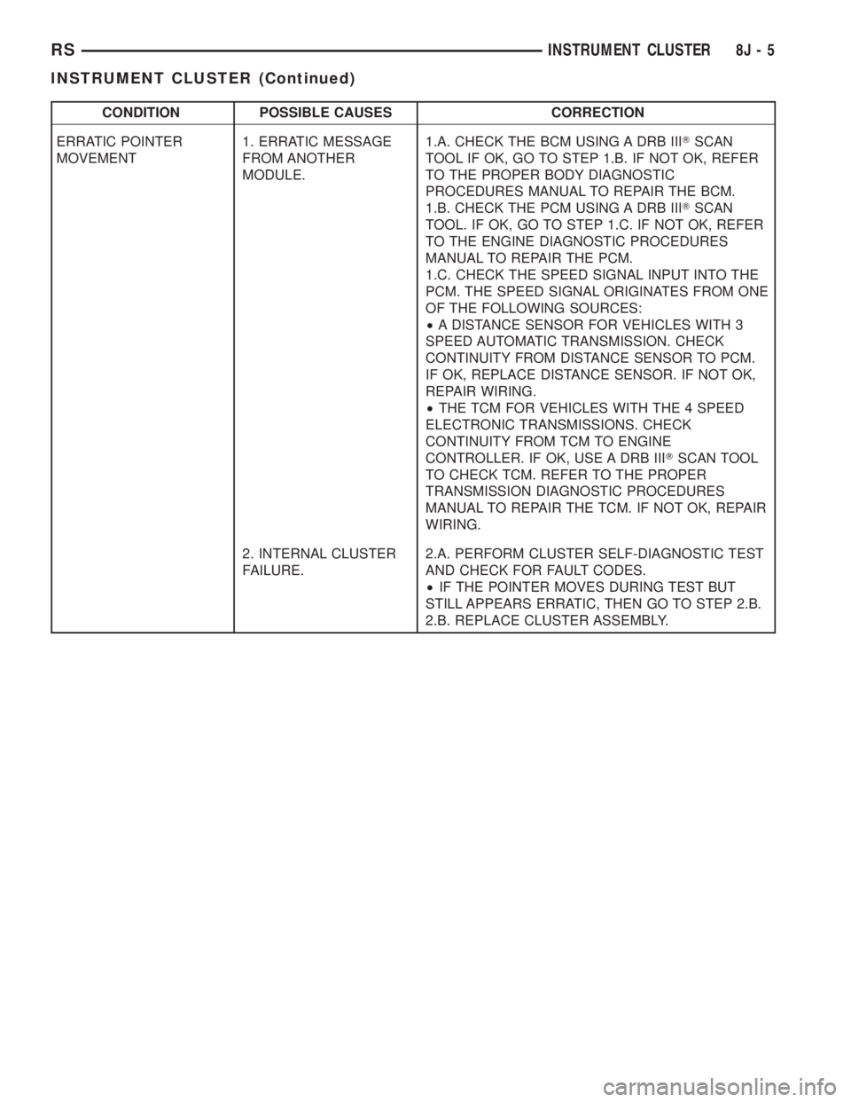
CONDITION POSSIBLE CAUSES CORRECTION
ERRATIC POINTER
MOVEMENT1. ERRATIC MESSAGE
FROM ANOTHER
MODULE.1.A. CHECK THE BCM USING A DRB IIITSCAN
TOOL IF OK, GO TO STEP 1.B. IF NOT OK, REFER
TO THE PROPER BODY DIAGNOSTIC
PROCEDURES MANUAL TO REPAIR THE BCM.
1.B. CHECK THE PCM USING A DRB IIITSCAN
TOOL. IF OK, GO TO STEP 1.C. IF NOT OK, REFER
TO THE ENGINE DIAGNOSTIC PROCEDURES
MANUAL TO REPAIR THE PCM.
1.C. CHECK THE SPEED SIGNAL INPUT INTO THE
PCM. THE SPEED SIGNAL ORIGINATES FROM ONE
OF THE FOLLOWING SOURCES:
²A DISTANCE SENSOR FOR VEHICLES WITH 3
SPEED AUTOMATIC TRANSMISSION. CHECK
CONTINUITY FROM DISTANCE SENSOR TO PCM.
IF OK, REPLACE DISTANCE SENSOR. IF NOT OK,
REPAIR WIRING.
²THE TCM FOR VEHICLES WITH THE 4 SPEED
ELECTRONIC TRANSMISSIONS. CHECK
CONTINUITY FROM TCM TO ENGINE
CONTROLLER. IF OK, USE A DRB IIITSCAN TOOL
TO CHECK TCM. REFER TO THE PROPER
TRANSMISSION DIAGNOSTIC PROCEDURES
MANUAL TO REPAIR THE TCM. IF NOT OK, REPAIR
WIRING.
2. INTERNAL CLUSTER
FAILURE.2.A. PERFORM CLUSTER SELF-DIAGNOSTIC TEST
AND CHECK FOR FAULT CODES.
²IF THE POINTER MOVES DURING TEST BUT
STILL APPEARS ERRATIC, THEN GO TO STEP 2.B.
2.B. REPLACE CLUSTER ASSEMBLY.
RSINSTRUMENT CLUSTER8J-5
INSTRUMENT CLUSTER (Continued)
Page 1932 of 4284
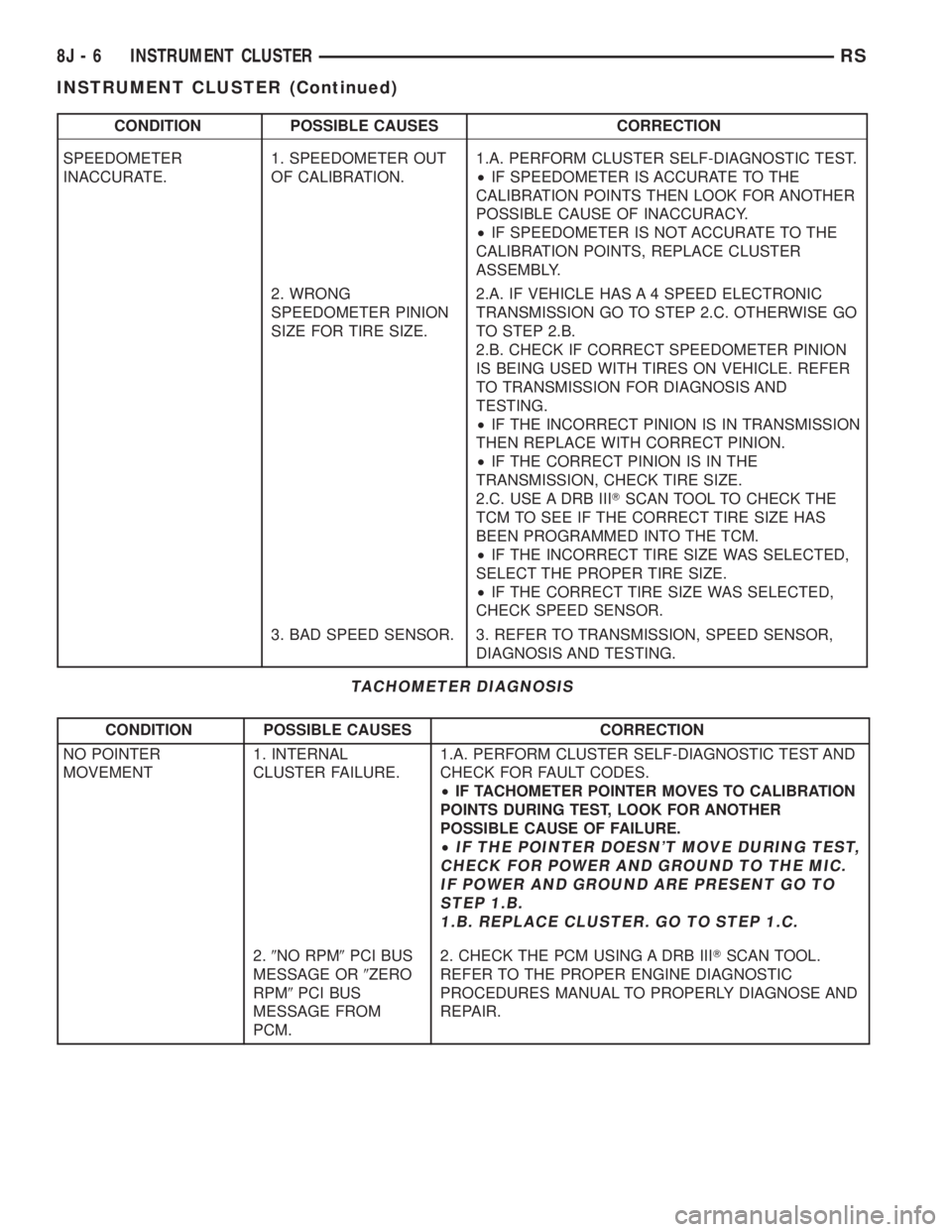
CONDITION POSSIBLE CAUSES CORRECTION
SPEEDOMETER
INACCURATE.1. SPEEDOMETER OUT
OF CALIBRATION.1.A. PERFORM CLUSTER SELF-DIAGNOSTIC TEST.
²IF SPEEDOMETER IS ACCURATE TO THE
CALIBRATION POINTS THEN LOOK FOR ANOTHER
POSSIBLE CAUSE OF INACCURACY.
²IF SPEEDOMETER IS NOT ACCURATE TO THE
CALIBRATION POINTS, REPLACE CLUSTER
ASSEMBLY.
2. WRONG
SPEEDOMETER PINION
SIZE FOR TIRE SIZE.2.A. IF VEHICLE HAS A 4 SPEED ELECTRONIC
TRANSMISSION GO TO STEP 2.C. OTHERWISE GO
TO STEP 2.B.
2.B. CHECK IF CORRECT SPEEDOMETER PINION
IS BEING USED WITH TIRES ON VEHICLE. REFER
TO TRANSMISSION FOR DIAGNOSIS AND
TESTING.
²IF THE INCORRECT PINION IS IN TRANSMISSION
THEN REPLACE WITH CORRECT PINION.
²IF THE CORRECT PINION IS IN THE
TRANSMISSION, CHECK TIRE SIZE.
2.C. USE A DRB IIITSCAN TOOL TO CHECK THE
TCM TO SEE IF THE CORRECT TIRE SIZE HAS
BEEN PROGRAMMED INTO THE TCM.
²IF THE INCORRECT TIRE SIZE WAS SELECTED,
SELECT THE PROPER TIRE SIZE.
²IF THE CORRECT TIRE SIZE WAS SELECTED,
CHECK SPEED SENSOR.
3. BAD SPEED SENSOR. 3. REFER TO TRANSMISSION, SPEED SENSOR,
DIAGNOSIS AND TESTING.
TACHOMETER DIAGNOSIS
CONDITION POSSIBLE CAUSES CORRECTION
NO POINTER
MOVEMENT1. INTERNAL
CLUSTER FAILURE.1.A. PERFORM CLUSTER SELF-DIAGNOSTIC TEST AND
CHECK FOR FAULT CODES.
²IF TACHOMETER POINTER MOVES TO CALIBRATION
POINTS DURING TEST, LOOK FOR ANOTHER
POSSIBLE CAUSE OF FAILURE.
²
IF THE POINTER DOESN'T MOVE DURING TEST,
CHECK FOR POWER AND GROUND TO THE MIC.
IF POWER AND GROUND ARE PRESENT GO TO
STEP 1.B.
1.B. REPLACE CLUSTER. GO TO STEP 1.C.
2.9NO RPM9PCI BUS
MESSAGE OR9ZERO
RPM9PCI BUS
MESSAGE FROM
PCM.2. CHECK THE PCM USING A DRB IIITSCAN TOOL.
REFER TO THE PROPER ENGINE DIAGNOSTIC
PROCEDURES MANUAL TO PROPERLY DIAGNOSE AND
REPAIR.
8J - 6 INSTRUMENT CLUSTERRS
INSTRUMENT CLUSTER (Continued)
Page 1933 of 4284
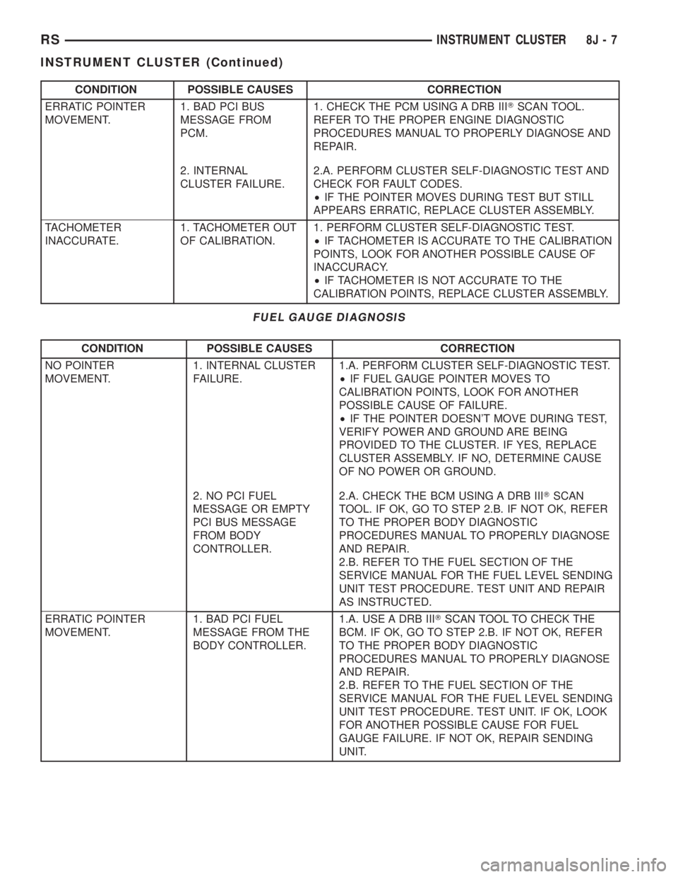
CONDITION POSSIBLE CAUSES CORRECTION
ERRATIC POINTER
MOVEMENT.1. BAD PCI BUS
MESSAGE FROM
PCM.1. CHECK THE PCM USING A DRB IIITSCAN TOOL.
REFER TO THE PROPER ENGINE DIAGNOSTIC
PROCEDURES MANUAL TO PROPERLY DIAGNOSE AND
REPAIR.
2. INTERNAL
CLUSTER FAILURE.2.A. PERFORM CLUSTER SELF-DIAGNOSTIC TEST AND
CHECK FOR FAULT CODES.
²IF THE POINTER MOVES DURING TEST BUT STILL
APPEARS ERRATIC, REPLACE CLUSTER ASSEMBLY.
TACHOMETER
INACCURATE.1. TACHOMETER OUT
OF CALIBRATION.1. PERFORM CLUSTER SELF-DIAGNOSTIC TEST.
²IF TACHOMETER IS ACCURATE TO THE CALIBRATION
POINTS, LOOK FOR ANOTHER POSSIBLE CAUSE OF
INACCURACY.
²IF TACHOMETER IS NOT ACCURATE TO THE
CALIBRATION POINTS, REPLACE CLUSTER ASSEMBLY.
FUEL GAUGE DIAGNOSIS
CONDITION POSSIBLE CAUSES CORRECTION
NO POINTER
MOVEMENT.1. INTERNAL CLUSTER
FAILURE.1.A. PERFORM CLUSTER SELF-DIAGNOSTIC TEST.
²IF FUEL GAUGE POINTER MOVES TO
CALIBRATION POINTS, LOOK FOR ANOTHER
POSSIBLE CAUSE OF FAILURE.
²IF THE POINTER DOESN'T MOVE DURING TEST,
VERIFY POWER AND GROUND ARE BEING
PROVIDED TO THE CLUSTER. IF YES, REPLACE
CLUSTER ASSEMBLY. IF NO, DETERMINE CAUSE
OF NO POWER OR GROUND.
2. NO PCI FUEL
MESSAGE OR EMPTY
PCI BUS MESSAGE
FROM BODY
CONTROLLER.2.A. CHECK THE BCM USING A DRB IIITSCAN
TOOL. IF OK, GO TO STEP 2.B. IF NOT OK, REFER
TO THE PROPER BODY DIAGNOSTIC
PROCEDURES MANUAL TO PROPERLY DIAGNOSE
AND REPAIR.
2.B. REFER TO THE FUEL SECTION OF THE
SERVICE MANUAL FOR THE FUEL LEVEL SENDING
UNIT TEST PROCEDURE. TEST UNIT AND REPAIR
AS INSTRUCTED.
ERRATIC POINTER
MOVEMENT.1. BAD PCI FUEL
MESSAGE FROM THE
BODY CONTROLLER.1.A. USE A DRB IIITSCAN TOOL TO CHECK THE
BCM. IF OK, GO TO STEP 2.B. IF NOT OK, REFER
TO THE PROPER BODY DIAGNOSTIC
PROCEDURES MANUAL TO PROPERLY DIAGNOSE
AND REPAIR.
2.B. REFER TO THE FUEL SECTION OF THE
SERVICE MANUAL FOR THE FUEL LEVEL SENDING
UNIT TEST PROCEDURE. TEST UNIT. IF OK, LOOK
FOR ANOTHER POSSIBLE CAUSE FOR FUEL
GAUGE FAILURE. IF NOT OK, REPAIR SENDING
UNIT.
RSINSTRUMENT CLUSTER8J-7
INSTRUMENT CLUSTER (Continued)