check engine CHRYSLER VOYAGER 2001 Service Manual
[x] Cancel search | Manufacturer: CHRYSLER, Model Year: 2001, Model line: VOYAGER, Model: CHRYSLER VOYAGER 2001Pages: 4284, PDF Size: 83.53 MB
Page 2739 of 4284
INSTALLATION - CRANKSHAFT MAIN
BEARINGS
NOTE: One main bearing should be selectively fit-
ted while all other main bearing caps are properly
tightened.
(1) For main bearing fitting procedure, (Refer to 9
- ENGINE/ENGINE BLOCK/CRANKSHAFT MAIN
BEARINGS - STANDARD PROCEDURE)
(2) Start bearing in place, and insert Main Bearing
Tool C-3059 into oil hole of crankshaft (Fig. 60).
(3) Slowly rotate crankshaft counterclockwise slid-
ing the bearing into position. Remove Special Main
Bearing Tool C-3059.
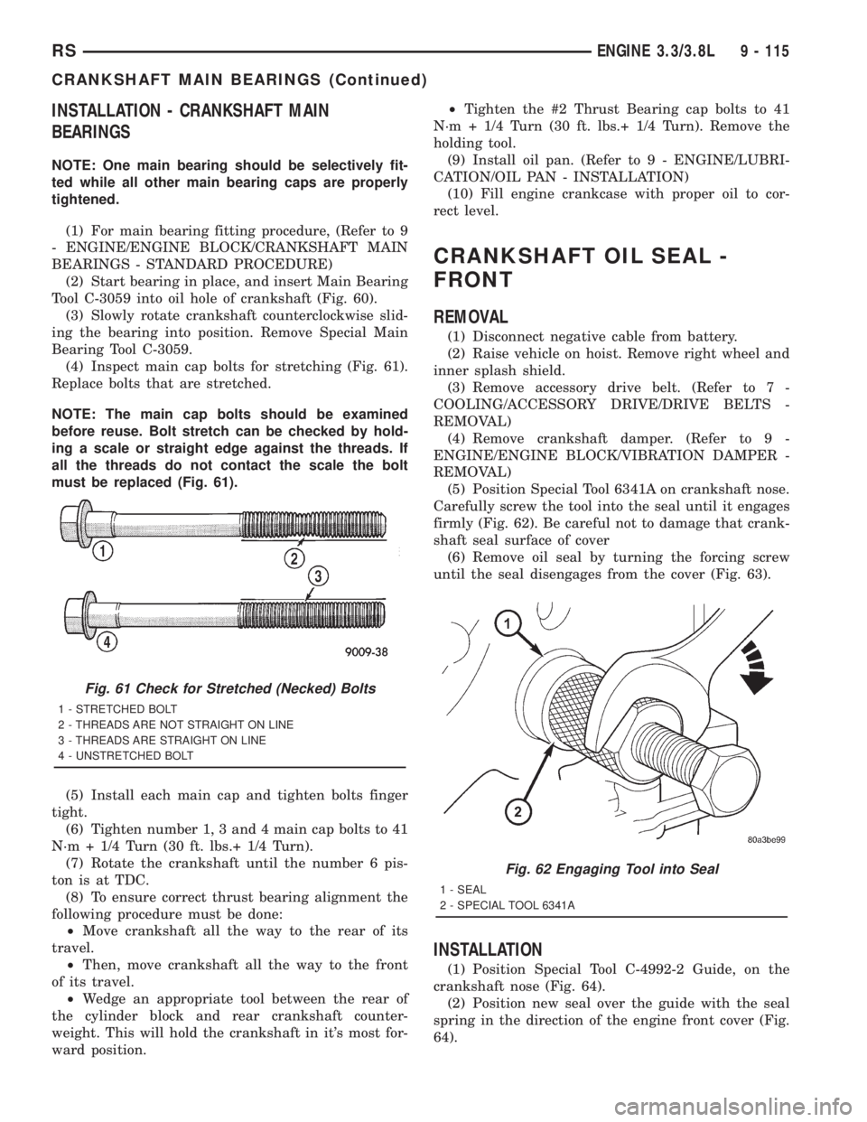
(4) Inspect main cap bolts for stretching (Fig. 61).
Replace bolts that are stretched.
NOTE: The main cap bolts should be examined
before reuse. Bolt stretch can be checked by hold-
ing a scale or straight edge against the threads. If
all the threads do not contact the scale the bolt
must be replaced (Fig. 61).
(5) Install each main cap and tighten bolts finger
tight.
(6) Tighten number 1, 3 and 4 main cap bolts to 41
N´m + 1/4 Turn (30 ft. lbs.+ 1/4 Turn).
(7) Rotate the crankshaft until the number 6 pis-
ton is at TDC.
(8) To ensure correct thrust bearing alignment the
following procedure must be done:
²Move crankshaft all the way to the rear of its
travel.
²Then, move crankshaft all the way to the front
of its travel.
²Wedge an appropriate tool between the rear of
the cylinder block and rear crankshaft counter-
weight. This will hold the crankshaft in it's most for-
ward position.²Tighten the #2 Thrust Bearing cap bolts to 41
N´m + 1/4 Turn (30 ft. lbs.+ 1/4 Turn). Remove the
holding tool.
(9) Install oil pan. (Refer to 9 - ENGINE/LUBRI-
CATION/OIL PAN - INSTALLATION)
(10) Fill engine crankcase with proper oil to cor-
rect level.
CRANKSHAFT OIL SEAL -
FRONT
REMOVAL
(1) Disconnect negative cable from battery.
(2) Raise vehicle on hoist. Remove right wheel and
inner splash shield.
(3) Remove accessory drive belt. (Refer to 7 -
COOLING/ACCESSORY DRIVE/DRIVE BELTS -
REMOVAL)
(4) Remove crankshaft damper. (Refer to 9 -
ENGINE/ENGINE BLOCK/VIBRATION DAMPER -
REMOVAL)
(5) Position Special Tool 6341A on crankshaft nose.
Carefully screw the tool into the seal until it engages
firmly (Fig. 62). Be careful not to damage that crank-
shaft seal surface of cover
(6) Remove oil seal by turning the forcing screw
until the seal disengages from the cover (Fig. 63).
INSTALLATION
(1) Position Special Tool C-4992-2 Guide, on the
crankshaft nose (Fig. 64).
(2) Position new seal over the guide with the seal
spring in the direction of the engine front cover (Fig.
64).
Fig. 61 Check for Stretched (Necked) Bolts
1 - STRETCHED BOLT
2 - THREADS ARE NOT STRAIGHT ON LINE
3 - THREADS ARE STRAIGHT ON LINE
4 - UNSTRETCHED BOLT
Fig. 62 Engaging Tool into Seal
1 - SEAL
2 - SPECIAL TOOL 6341A
RSENGINE 3.3/3.8L9 - 115
CRANKSHAFT MAIN BEARINGS (Continued)
Page 2742 of 4284
FLEX PLATE
REMOVAL
(1) Remove the transaxle. (Refer to 21 - TRANS-
MISSION/TRANSAXLE/AUTOMATIC - 31TH -
REMOVAL) (Refer to 21 - TRANSMISSION/TRAN-
SAXLE/AUTOMATIC - 41TE - REMOVAL)
(2) Remove flex plate attaching bolts.
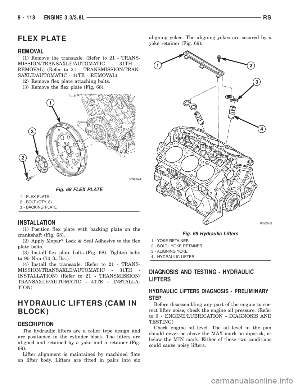
(3) Remove the flex plate (Fig. 68).
INSTALLATION
(1) Position flex plate with backing plate on the
crankshaft (Fig. 68).
(2) Apply MopartLock & Seal Adhesive to the flex
plate bolts.
(3) Install flex plate bolts (Fig. 68). Tighten bolts
to 95 N´m (70 ft. lbs.).
(4) Install the transaxle. (Refer to 21 - TRANS-
MISSION/TRANSAXLE/AUTOMATIC - 31TH -
INSTALLATION) (Refer to 21 - TRANSMISSION/
TRANSAXLE/AUTOMATIC - 41TE - INSTALLA-
TION)
HYDRAULIC LIFTERS (CAM IN
BLOCK)
DESCRIPTION
The hydraulic lifters are a roller type design and
are positioned in the cylinder block. The lifters are
aligned and retained by a yoke and a retainer (Fig.
69).
Lifter alignment is maintained by machined flats
on lifter body. Lifters are fitted in pairs into sixaligning yokes. The aligning yokes are secured by a
yoke retainer (Fig. 69).
DIAGNOSIS AND TESTING - HYDRAULIC
LIFTERS
HYDRAULIC LIFTERS DIAGNOSIS - PRELIMINARY
STEP
Before disassembling any part of the engine to cor-
rect lifter noise, check the engine oil pressure. (Refer
to 9 - ENGINE/LUBRICATION - DIAGNOSIS AND
TESTING)
Check engine oil level. The oil level in the pan
should never be above the MAX mark on dipstick, or
below the MIN mark. Either of these two conditions
could cause noisy lifters.
Fig. 68 FLEX PLATE
1 - FLEX PLATE
2 - BOLT (QTY. 8)
3 - BACKING PLATE
Fig. 69 Hydraulic Lifters
1 - YOKE RETAINER
2 - BOLT - YOKE RETAINER
3 - ALIGNING YOKE
4 - HYDRAULIC LIFTER
9 - 118 ENGINE 3.3/3.8LRS
Page 2743 of 4284
OIL LEVEL TOO HIGH
If oil level is above the MAX mark on dipstick, it is
possible for the connecting rods to dip into the oil
while engine is running and create foaming. Foam in
oil pan would be fed to the hydraulic lifters by the oil
pump causing them to become soft and allow valves
to seat noisily.
OIL LEVEL TOO LOW
Low oil level may allow pump to take in air which
when fed to the lifters it causes them to become soft
and allows valves to seat noisily. Any leaks on intake
side of pump, through which air can be drawn, will
create the same lifter noise. Check the lubrication
system from the intake strainer to the oil pump
cover, including the relief valve retainer cap. When
lifter noise is due to aeration, it may be intermittent
or constant, and usually more than one lifter will be
noisy. When oil level and leaks have been corrected,
the engine should be operated at fast idle to allow all
of the air inside of the lifters to be bled out.
VALVE TRAIN NOISE
To determine source of valve train noise, operate
engine at idle with cylinder head covers removed and
listen for source of the noise.
NOTE: Worn valve guides or cocked springs are
sometimes mistaken for noisy lifters. If such is the
case, noise may be dampened by applying side
thrust on the valve spring. If noise is not apprecia-
bly reduced, it can be assumed the noise is in the
tappet. Inspect the rocker arm push rod sockets
and push rod ends for wear.
Valve lifter noise ranges from light noise to a
heavy click. A light noise is usually caused by exces-
sive leak-down around the unit plunger which will
necessitate replacing the lifter, or by the plunger par-
tially sticking in the lifter body cylinder. A heavy
click is caused either by a lifter check valve not seat-
ing, or by foreign particles becoming wedged between
the plunger and the lifter body causing the plunger
to stick in the down position. This heavy click will be
accompanied by excessive clearance between the
valve stem and rocker arm as valve closes. In either
case, lifter assembly should be removed for inspec-
tion.
REMOVAL
(1) Remove the cylinder head(s). (Refer to 9 -
ENGINE/CYLINDER HEAD - REMOVAL)
(2) Remove the yoke retainer and aligning yokes
(Fig. 71).
(3) Remove the hydraulic lifters. If necessary use
Special Tool C-4129, or equivalent to remove liftersfrom bores. If lifters are to be reused, identify each
lifter to ensure installation in original location.
INSTALLATION
(1) Lubricate the lifters with engine oil.
NOTE: Position the lifter in bore with the lubrication
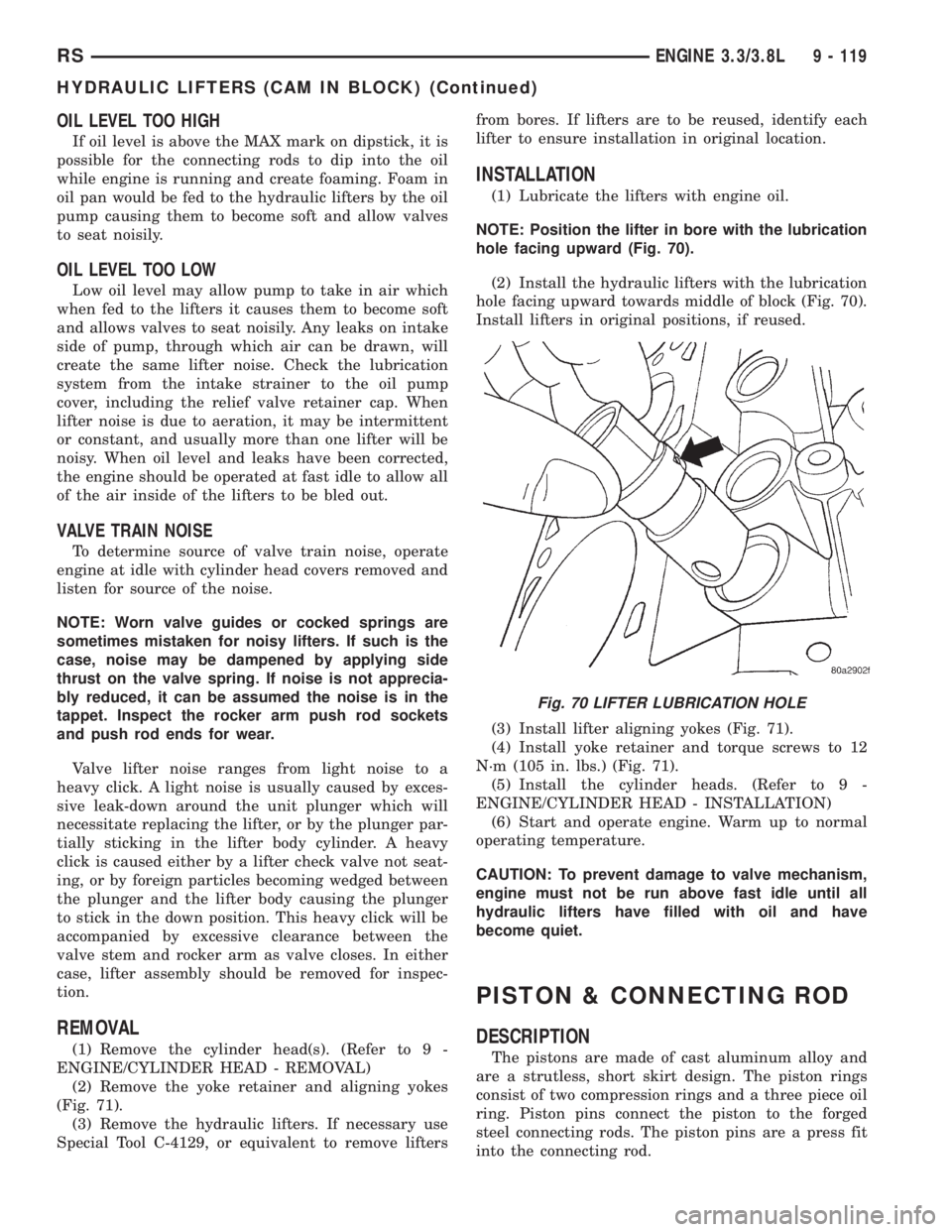
hole facing upward (Fig. 70).
(2) Install the hydraulic lifters with the lubrication
hole facing upward towards middle of block (Fig. 70).
Install lifters in original positions, if reused.
(3) Install lifter aligning yokes (Fig. 71).
(4) Install yoke retainer and torque screws to 12
N´m (105 in. lbs.) (Fig. 71).
(5) Install the cylinder heads. (Refer to 9 -
ENGINE/CYLINDER HEAD - INSTALLATION)
(6) Start and operate engine. Warm up to normal
operating temperature.
CAUTION: To prevent damage to valve mechanism,
engine must not be run above fast idle until all
hydraulic lifters have filled with oil and have
become quiet.
PISTON & CONNECTING ROD
DESCRIPTION
The pistons are made of cast aluminum alloy and
are a strutless, short skirt design. The piston rings
consist of two compression rings and a three piece oil
ring. Piston pins connect the piston to the forged
steel connecting rods. The piston pins are a press fit
into the connecting rod.
Fig. 70 LIFTER LUBRICATION HOLE
RSENGINE 3.3/3.8L9 - 119
HYDRAULIC LIFTERS (CAM IN BLOCK) (Continued)
Page 2744 of 4284
OPERATION
The piston and connecting rod is the link between
the combustion force to the crankshaft.
STANDARD PROCEDURES - FITTING
CONNECTING RODS
The bearing caps are not interchangeable or
reversible, and should be marked at removal to
ensure correct reassembly. The bearing shells must
be installed with the tangs inserted into the
machined grooves in the rods and caps. Install cap
with the tangs on the same side as the rod. For con-
necting rod bearing fitting (Refer to 9 - ENGINE/EN-
GINE BLOCK/CONNECTING ROD BEARINGS -
STANDARD PROCEDURE). Fit all connecting rods
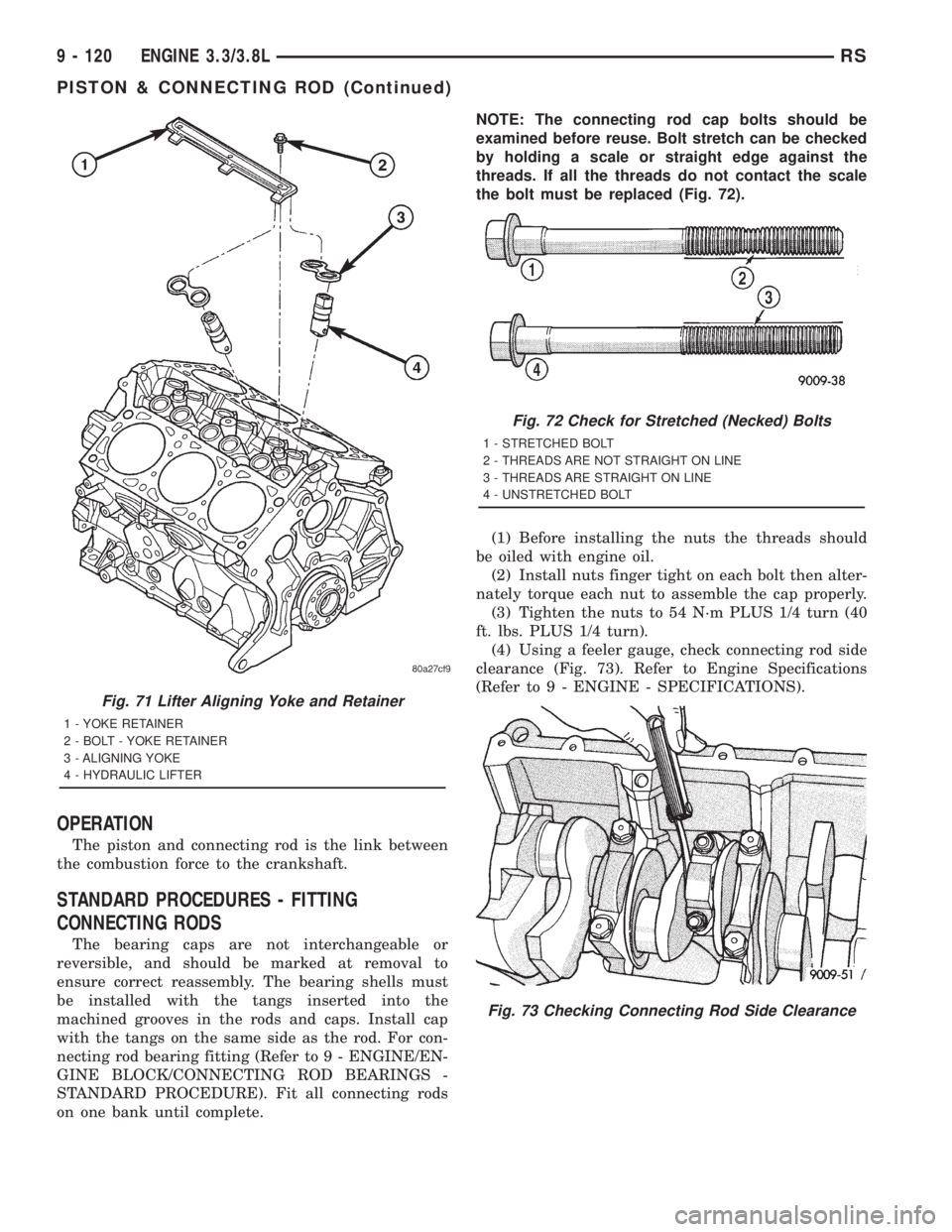
on one bank until complete.NOTE: The connecting rod cap bolts should be
examined before reuse. Bolt stretch can be checked
by holding a scale or straight edge against the
threads. If all the threads do not contact the scale
the bolt must be replaced (Fig. 72).
(1) Before installing the nuts the threads should
be oiled with engine oil.
(2) Install nuts finger tight on each bolt then alter-
nately torque each nut to assemble the cap properly.
(3) Tighten the nuts to 54 N´m PLUS 1/4 turn (40
ft. lbs. PLUS 1/4 turn).
(4) Using a feeler gauge, check connecting rod side
clearance (Fig. 73). Refer to Engine Specifications
(Refer to 9 - ENGINE - SPECIFICATIONS).
Fig. 71 Lifter Aligning Yoke and Retainer
1 - YOKE RETAINER
2 - BOLT - YOKE RETAINER
3 - ALIGNING YOKE
4 - HYDRAULIC LIFTER
Fig. 72 Check for Stretched (Necked) Bolts
1 - STRETCHED BOLT
2 - THREADS ARE NOT STRAIGHT ON LINE
3 - THREADS ARE STRAIGHT ON LINE
4 - UNSTRETCHED BOLT
Fig. 73 Checking Connecting Rod Side Clearance
9 - 120 ENGINE 3.3/3.8LRS
PISTON & CONNECTING ROD (Continued)
Page 2745 of 4284
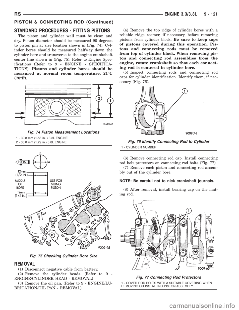
STANDARD PROCEDURES - FITTING PISTONS
The piston and cylinder wall must be clean and
dry. Piston diameter should be measured 90 degrees
to piston pin at size location shown in (Fig. 74). Cyl-
inder bores should be measured halfway down the
cylinder bore and transverse to the engine crankshaft
center line shown in (Fig. 75). Refer to Engine Spec-
ifications (Refer to 9 - ENGINE - SPECIFICA-
TIONS).Pistons and cylinder bores should be
measured at normal room temperature, 21ÉC
(70ÉF).
REMOVAL
(1) Disconnect negative cable from battery.
(2) Remove the cylinder heads. (Refer to 9 -
ENGINE/CYLINDER HEAD - REMOVAL)
(3) Remove the oil pan. (Refer to 9 - ENGINE/LU-
BRICATION/OIL PAN - REMOVAL)(4) Remove the top ridge of cylinder bores with a
reliable ridge reamer, if necessary, before removing
pistons from cylinder block.Be sure to keep tops
of pistons covered during this operation. Pis-
tons and connecting rods must be removed
from top of cylinder block. When removing pis-
ton and connecting rod assemblies from the
engine, rotate crankshaft so that each connect-
ing rod is centered in cylinder bore.
(5) Inspect connecting rods and connecting rod
caps for cylinder identification. Identify them, if nec-
essary (Fig. 76).
(6) Remove connecting rod cap. Install connecting
rod bolt protectors on connecting rod bolts (Fig. 77).
(7) Remove each piston and connecting rod assem-
bly out of the cylinder bore.
NOTE: Be careful not to nick crankshaft journals.
(8) After removal, install bearing cap on the mat-
ing rod.
Fig. 74 Piston Measurement Locations
1 - 39.8 mm (1.56 in. ) 3.3L ENGINE
2 - 33.0 mm (1.29 in.) 3.8L ENGINE
Fig. 75 Checking Cylinder Bore Size
Fig. 76 Identify Connecting Rod to Cylinder
1 - CYLINDER NUMBER
Fig. 77 Connecting Rod Protectors
1 - COVER ROD BOLTS WITH A SUITABLE COVERING WHEN
REMOVING OR INSTALLING PISTON ASSEMBLY
RSENGINE 3.3/3.8L9 - 121
PISTON & CONNECTING ROD (Continued)
Page 2748 of 4284
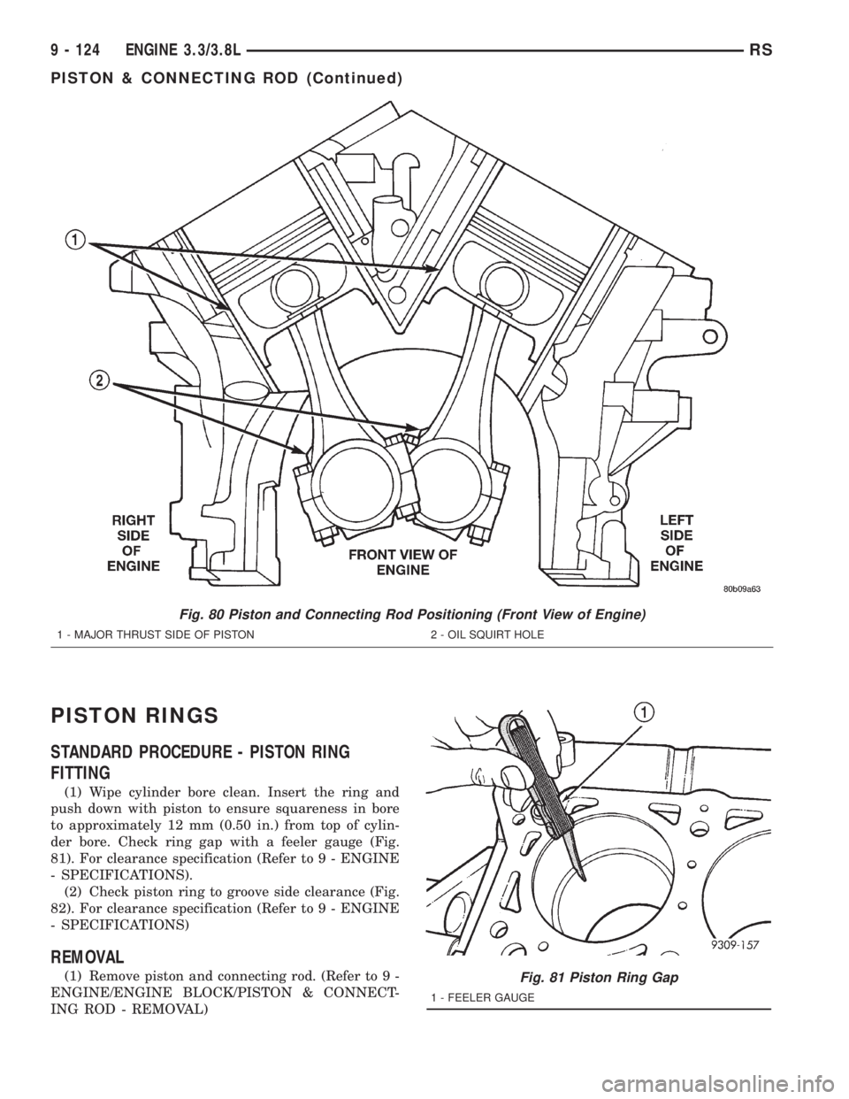
PISTON RINGS
STANDARD PROCEDURE - PISTON RING
FITTING
(1) Wipe cylinder bore clean. Insert the ring and
push down with piston to ensure squareness in bore
to approximately 12 mm (0.50 in.) from top of cylin-
der bore. Check ring gap with a feeler gauge (Fig.
81). For clearance specification (Refer to 9 - ENGINE
- SPECIFICATIONS).
(2) Check piston ring to groove side clearance (Fig.
82). For clearance specification (Refer to 9 - ENGINE
- SPECIFICATIONS)
REMOVAL
(1) Remove piston and connecting rod. (Refer to 9 -
ENGINE/ENGINE BLOCK/PISTON & CONNECT-
ING ROD - REMOVAL)
Fig. 80 Piston and Connecting Rod Positioning (Front View of Engine)
1 - MAJOR THRUST SIDE OF PISTON 2 - OIL SQUIRT HOLE
Fig. 81 Piston Ring Gap
1 - FEELER GAUGE
9 - 124 ENGINE 3.3/3.8LRS
PISTON & CONNECTING ROD (Continued)
Page 2756 of 4284
OIL
STANDARD PROCEDURE - ENGINE OIL AND
FILTER CHANGE
Change engine oil at mileage and time intervals
described in the Maintenance Schedule. (Refer to
LUBRICATION & MAINTENANCE/MAINTE-
NANCE SCHEDULES - DESCRIPTION)
WARNING: NEW OR USED ENGINE OIL CAN BE
IRRITATING TO THE SKIN. AVOID PROLONGED OR
REPEATED SKIN CONTACT WITH ENGINE OIL.
CONTAMINANTS IN USED ENGINE OIL, CAUSED BY
INTERNAL COMBUSTION, CAN BE HAZARDOUS TO
YOUR HEALTH. THOROUGHLY WASH EXPOSED
SKIN WITH SOAP AND WATER. DO NOT WASH
SKIN WITH GASOLINE, DIESEL FUEL, THINNER, OR
SOLVENTS, HEALTH PROBLEMS CAN RESULT. DO
NOT POLLUTE, DISPOSE OF USED ENGINE OIL
PROPERLY. CONTACT YOUR DEALER OR GOVERN-
MENT AGENCY FOR LOCATION OF COLLECTION
CENTER IN YOUR AREA.
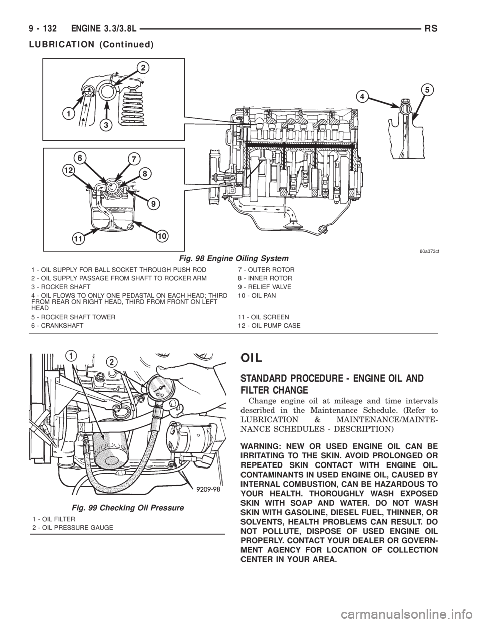
Fig. 98 Engine Oiling System
1 - OIL SUPPLY FOR BALL SOCKET THROUGH PUSH ROD 7 - OUTER ROTOR
2 - OIL SUPPLY PASSAGE FROM SHAFT TO ROCKER ARM 8 - INNER ROTOR
3 - ROCKER SHAFT 9 - RELIEF VALVE
4 - OIL FLOWS TO ONLY ONE PEDASTAL ON EACH HEAD; THIRD
FROM REAR ON RIGHT HEAD, THIRD FROM FRONT ON LEFT
HEAD10 - OIL PAN
5 - ROCKER SHAFT TOWER 11 - OIL SCREEN
6 - CRANKSHAFT 12 - OIL PUMP CASE
Fig. 99 Checking Oil Pressure
1 - OIL FILTER
2 - OIL PRESSURE GAUGE
9 - 132 ENGINE 3.3/3.8LRS
LUBRICATION (Continued)
Page 2757 of 4284
Run engine until achieving normal operating tem-
perature.
(1) Position the vehicle on a level surface and turn
engine off.
(2) Hoist and support vehicle on safety stands.
Refer to Hoisting and Jacking Recommendations.
(Refer to LUBRICATION & MAINTENANCE/HOIST-
ING - STANDARD PROCEDURE)
(3) Remove oil fill cap.
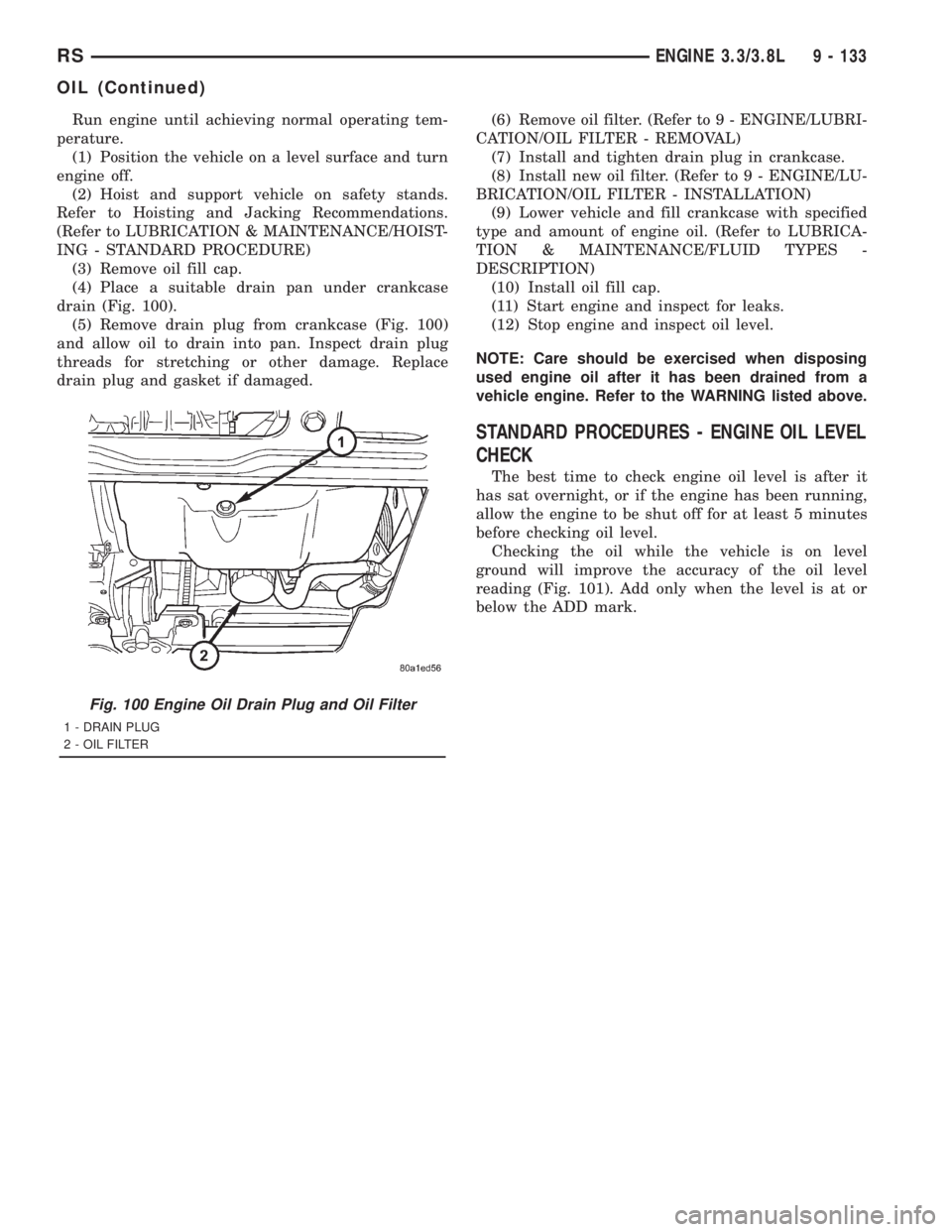
(4) Place a suitable drain pan under crankcase
drain (Fig. 100).
(5) Remove drain plug from crankcase (Fig. 100)
and allow oil to drain into pan. Inspect drain plug
threads for stretching or other damage. Replace
drain plug and gasket if damaged.(6) Remove oil filter. (Refer to 9 - ENGINE/LUBRI-
CATION/OIL FILTER - REMOVAL)
(7) Install and tighten drain plug in crankcase.
(8) Install new oil filter. (Refer to 9 - ENGINE/LU-
BRICATION/OIL FILTER - INSTALLATION)
(9) Lower vehicle and fill crankcase with specified
type and amount of engine oil. (Refer to LUBRICA-
TION & MAINTENANCE/FLUID TYPES -
DESCRIPTION)
(10) Install oil fill cap.
(11) Start engine and inspect for leaks.
(12) Stop engine and inspect oil level.
NOTE: Care should be exercised when disposing
used engine oil after it has been drained from a
vehicle engine. Refer to the WARNING listed above.
STANDARD PROCEDURES - ENGINE OIL LEVEL
CHECK
The best time to check engine oil level is after it
has sat overnight, or if the engine has been running,
allow the engine to be shut off for at least 5 minutes
before checking oil level.
Checking the oil while the vehicle is on level
ground will improve the accuracy of the oil level
reading (Fig. 101). Add only when the level is at or
below the ADD mark.
Fig. 100 Engine Oil Drain Plug and Oil Filter
1 - DRAIN PLUG
2 - OIL FILTER
RSENGINE 3.3/3.8L9 - 133
OIL (Continued)
Page 2759 of 4284
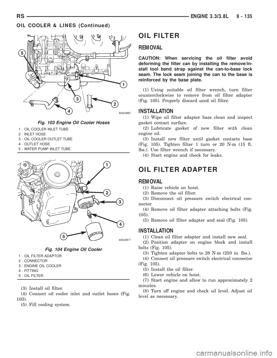
(3) Install oil filter.
(4) Connect oil cooler inlet and outlet hoses (Fig.
103).
(5) Fill cooling system.
OIL FILTER
REMOVAL
CAUTION: When servicing the oil filter avoid
deforming the filter can by installing the remove/in-
stall tool band strap against the can-to-base lock
seam. The lock seam joining the can to the base is
reinforced by the base plate.
(1) Using suitable oil filter wrench, turn filter
counterclockwise to remove from oil filter adapter
(Fig. 105). Properly discard used oil filter.
INSTALLATION
(1) Wipe oil filter adapter base clean and inspect
gasket contact surface.
(2) Lubricate gasket of new filter with clean
engine oil.
(3) Install new filter until gasket contacts base
(Fig. 105). Tighten filter 1 turn or 20 N´m (15 ft.
lbs.). Use filter wrench if necessary.
(4) Start engine and check for leaks.
OIL FILTER ADAPTER
REMOVAL
(1) Raise vehicle on hoist.
(2) Remove the oil filter.
(3) Disconnect oil pressure switch electrical con-
nector.
(4) Remove oil filter adapter attaching bolts (Fig.
105).
(5) Remove oil filter adapter and seal (Fig. 105).
INSTALLATION
(1) Clean oil filter adapter and install new seal.
(2) Position adapter on engine block and install
bolts (Fig. 105).
(3) Tighten adapter bolts to 28 N´m (250 in. lbs.).
(4) Connect oil pressure switch electrical connector
(Fig. 105).
(5) Install the oil filter.
(6) Lower vehicle on hoist.
(7) Start engine and allow to run approximately 2
minutes.
(8) Turn off engine and check oil level. Adjust oil
level as necessary.
Fig. 103 Engine Oil Cooler Hoses
1 - OIL COOLER INLET TUBE
2 - INLET HOSE
3 - OIL COOLER OUTLET TUBE
4 - OUTLET HOSE
5 - WATER PUMP INLET TUBE
Fig. 104 Engine Oil Cooler
1 - OIL FILTER ADAPTOR
2 - CONNECTOR
3 - ENGINE OIL COOLER
4 - FITTING
5 - OIL FILTER
RSENGINE 3.3/3.8L9 - 135
OIL COOLER & LINES (Continued)
Page 2762 of 4284
OPERATION
The oil pressure switch provides a ground for the
instrument cluster low oil pressure indicator light.
The switch receives oil pressure input from the
engine main oil gallery. When engine oil pressure is
greater than 27.5 Kpa (4 psi), the switch contacts
open, providing a open circuit to the low pressure
indicator light. For wiring circuits and diagnostic
information, (Refer to Appropriate Wiring/Diagnostic
Information).
REMOVAL
(1) Raise vehicle on hoist.
(2) Disconnect electrical connector from switch.
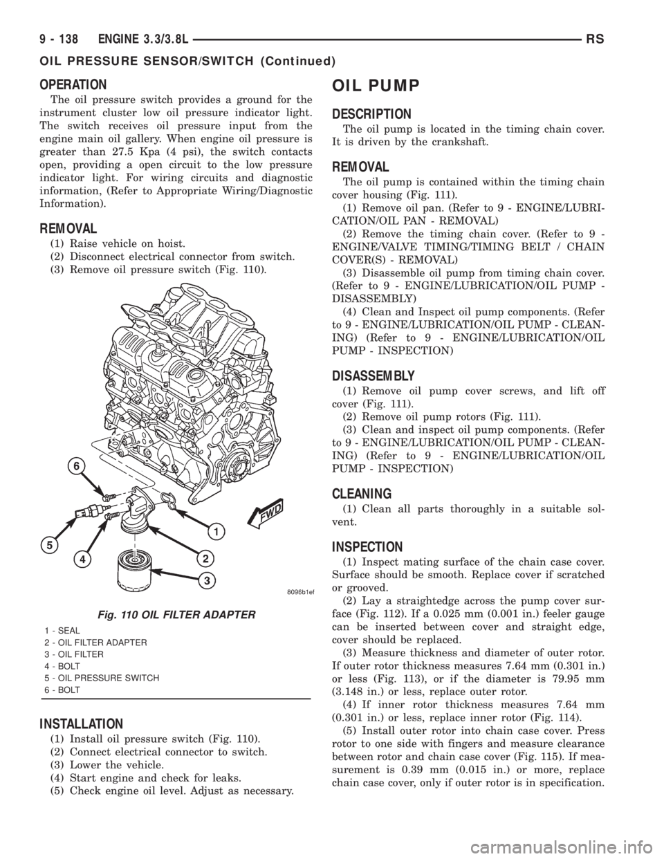
(3) Remove oil pressure switch (Fig. 110).
INSTALLATION
(1) Install oil pressure switch (Fig. 110).
(2) Connect electrical connector to switch.
(3) Lower the vehicle.
(4) Start engine and check for leaks.
(5) Check engine oil level. Adjust as necessary.
OIL PUMP
DESCRIPTION
The oil pump is located in the timing chain cover.
It is driven by the crankshaft.
REMOVAL
The oil pump is contained within the timing chain
cover housing (Fig. 111).
(1) Remove oil pan. (Refer to 9 - ENGINE/LUBRI-
CATION/OIL PAN - REMOVAL)
(2) Remove the timing chain cover. (Refer to 9 -
ENGINE/VALVE TIMING/TIMING BELT / CHAIN
COVER(S) - REMOVAL)
(3) Disassemble oil pump from timing chain cover.
(Refer to 9 - ENGINE/LUBRICATION/OIL PUMP -
DISASSEMBLY)
(4) Clean and Inspect oil pump components. (Refer
to 9 - ENGINE/LUBRICATION/OIL PUMP - CLEAN-
ING) (Refer to 9 - ENGINE/LUBRICATION/OIL
PUMP - INSPECTION)
DISASSEMBLY
(1) Remove oil pump cover screws, and lift off
cover (Fig. 111).
(2) Remove oil pump rotors (Fig. 111).
(3) Clean and inspect oil pump components. (Refer
to 9 - ENGINE/LUBRICATION/OIL PUMP - CLEAN-
ING) (Refer to 9 - ENGINE/LUBRICATION/OIL
PUMP - INSPECTION)
CLEANING
(1) Clean all parts thoroughly in a suitable sol-
vent.
INSPECTION
(1) Inspect mating surface of the chain case cover.
Surface should be smooth. Replace cover if scratched
or grooved.
(2) Lay a straightedge across the pump cover sur-
face (Fig. 112). If a 0.025 mm (0.001 in.) feeler gauge
can be inserted between cover and straight edge,
cover should be replaced.
(3) Measure thickness and diameter of outer rotor.
If outer rotor thickness measures 7.64 mm (0.301 in.)
or less (Fig. 113), or if the diameter is 79.95 mm
(3.148 in.) or less, replace outer rotor.
(4) If inner rotor thickness measures 7.64 mm
(0.301 in.) or less, replace inner rotor (Fig. 114).
(5) Install outer rotor into chain case cover. Press
rotor to one side with fingers and measure clearance
between rotor and chain case cover (Fig. 115). If mea-
surement is 0.39 mm (0.015 in.) or more, replace
chain case cover, only if outer rotor is in specification.
Fig. 110 OIL FILTER ADAPTER
1 - SEAL
2 - OIL FILTER ADAPTER
3 - OIL FILTER
4 - BOLT
5 - OIL PRESSURE SWITCH
6 - BOLT
9 - 138 ENGINE 3.3/3.8LRS
OIL PRESSURE SENSOR/SWITCH (Continued)