flat tire CHRYSLER VOYAGER 2001 Owner's Manual
[x] Cancel search | Manufacturer: CHRYSLER, Model Year: 2001, Model line: VOYAGER, Model: CHRYSLER VOYAGER 2001Pages: 4284, PDF Size: 83.53 MB
Page 2929 of 4284

NOTE: * There is some noise in all power steering
systems. One of the most common is a hissing
sound evident when turning the steering wheel
when at a standstill or when parking and the steer-
ing wheel is at the end of its travel. Hiss is a very
high frequency noise similar to that experienced
while slowly closing a water tap. The noise is
present in every valve and results when high veloc-ity fluid passes valve orifice edges. There is no
relationship between this noise and the perfor-
mance of the steering system.
NOTE: ** Power steering pump growl results from
the development of high pressure fluid flow. Nor-
mally this noise level should not be high enough to
be objectionable.
STEERING WHEEL FEEL
CONDITION POSSIBLE CAUSES CORRECTION
STEERING WHEEL/
COLUMN CLICKING,
CLUNKING OR RATTLING.1. Loose steering coupling pinch
bolt.1. Replace pinch bolt and torque to
specifications.
2. Steering column bearings. 2. Replace steering column.
STEERING WHEEL HAS
FORE AND AFT
LOOSENESS.1. Steering wheel retaining nut not
properly tightened and torqued.1. Tighten the steering wheel retaining nut
to its specified torque.
2. Steering column lower bearing
spring retainer slipped on steering
column shaft.2. Replace steering column.
3. Loose steering column to
instrument panel fasteners.3. Tighten fasteners to specified torque.
STEERING WHEEL OR
DASH VIBRATES DURING
LOW SPEED OR
STANDSTILL STEERING
MANEUVERS.1. Air in the fluid of the power
steering system.1. Bleed air from system following the
power steering pump initial operation
service procedure.*
2. Tires not properly inflated. 2. Inflate tires to the specified pressure.
3. Excessive engine vibration. 3. Ensure that the engine is running
properly.
4. Loose tie rod end jam nut. 4. Tighten the inner to outer tie rod jam nut
to the specified torque.
5.Overcharged air conditioning
system.5.Check air conditioning pump head
pressure and correct as necessary.
STEERING CATCHES,
STICKS IN CERTAIN
POSITIONS OR IS
DIFFICULT TO TURN.1. Low power steering fluid level. 1. Fill power steering fluid reservoir to
specified level and check for leaks.
2. Tires not inflated to specified
pressure.2. Inflate tires to the specified pressure.
3. Lack of lubrication in front lower
control arm ball joints.3. Lubricate ball joints if ball joints are not a
lubricated-for-life type ball joint. If ball joint
is a lubricated-for-life ball joint, replace ball
joint.
4. Worn or binding lower control arm
ball joint.4. Replace lower control arm ball joint.
RSSTEERING19-5
STEERING (Continued)
Page 2930 of 4284
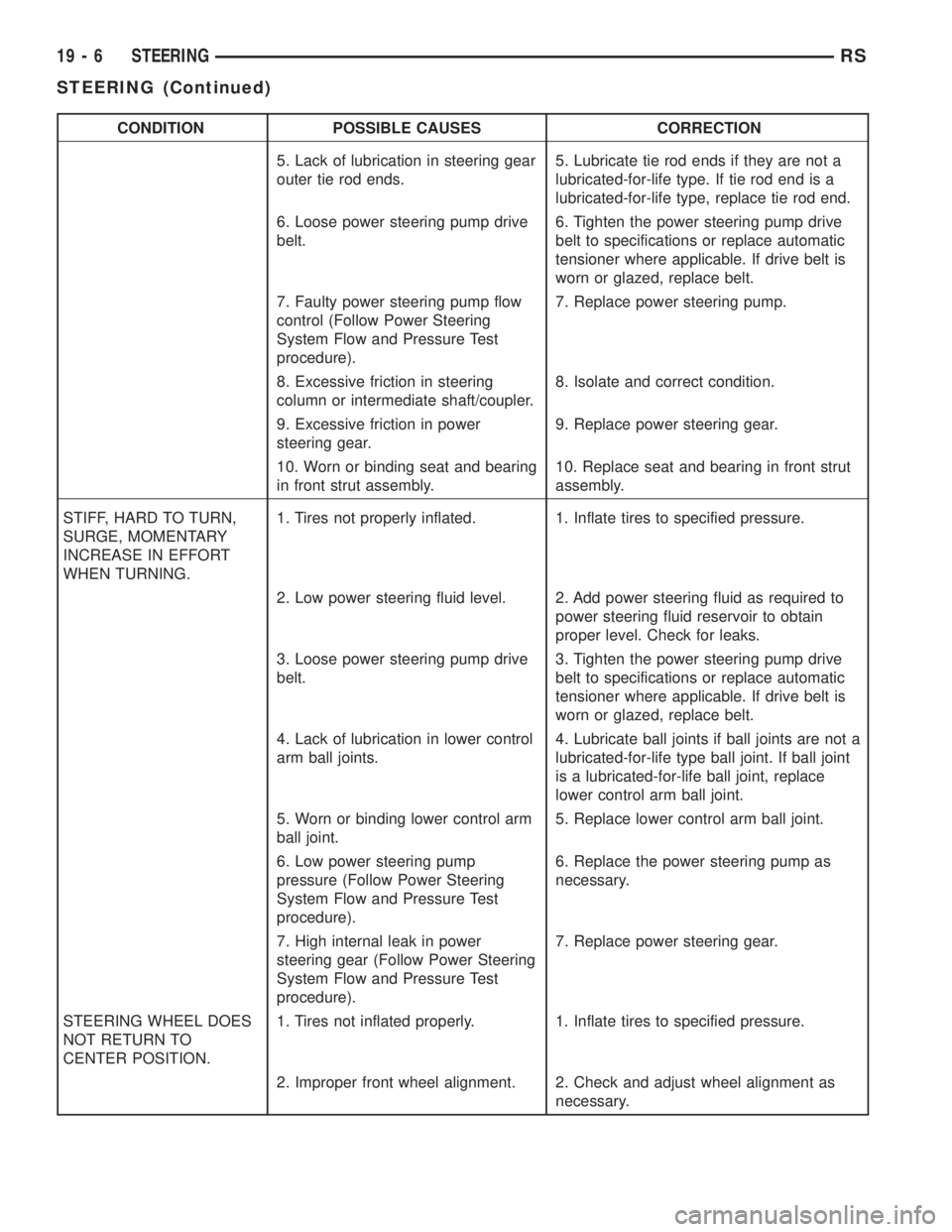
CONDITION POSSIBLE CAUSES CORRECTION
5. Lack of lubrication in steering gear
outer tie rod ends.5. Lubricate tie rod ends if they are not a
lubricated-for-life type. If tie rod end is a
lubricated-for-life type, replace tie rod end.
6. Loose power steering pump drive
belt.6. Tighten the power steering pump drive
belt to specifications or replace automatic
tensioner where applicable. If drive belt is
worn or glazed, replace belt.
7. Faulty power steering pump flow
control (Follow Power Steering
System Flow and Pressure Test
procedure).7. Replace power steering pump.
8. Excessive friction in steering
column or intermediate shaft/coupler.8. Isolate and correct condition.
9. Excessive friction in power
steering gear.9. Replace power steering gear.
10. Worn or binding seat and bearing
in front strut assembly.10. Replace seat and bearing in front strut
assembly.
STIFF, HARD TO TURN,
SURGE, MOMENTARY
INCREASE IN EFFORT
WHEN TURNING.1. Tires not properly inflated. 1. Inflate tires to specified pressure.
2. Low power steering fluid level. 2. Add power steering fluid as required to
power steering fluid reservoir to obtain
proper level. Check for leaks.
3. Loose power steering pump drive
belt.3. Tighten the power steering pump drive
belt to specifications or replace automatic
tensioner where applicable. If drive belt is
worn or glazed, replace belt.
4. Lack of lubrication in lower control
arm ball joints.4. Lubricate ball joints if ball joints are not a
lubricated-for-life type ball joint. If ball joint
is a lubricated-for-life ball joint, replace
lower control arm ball joint.
5. Worn or binding lower control arm
ball joint.5. Replace lower control arm ball joint.
6. Low power steering pump
pressure (Follow Power Steering
System Flow and Pressure Test
procedure).6. Replace the power steering pump as
necessary.
7. High internal leak in power
steering gear (Follow Power Steering
System Flow and Pressure Test
procedure).7. Replace power steering gear.
STEERING WHEEL DOES
NOT RETURN TO
CENTER POSITION.1. Tires not inflated properly. 1. Inflate tires to specified pressure.
2. Improper front wheel alignment. 2. Check and adjust wheel alignment as
necessary.
19 - 6 STEERINGRS
STEERING (Continued)
Page 3363 of 4284
TIRES/WHEELS
TABLE OF CONTENTS
page page
TIRES/WHEELS
DIAGNOSIS AND TESTING..................1
TIRE AND WHEEL VIBRATION..............1
STANDARD PROCEDURE...................4
TIRE AND WHEEL BALANCE...............4
TIRE AND WHEEL MATCH MOUNTING.......6
TIRE AND WHEEL ROTATION..............6
REMOVAL...............................7
INSTALLATION............................7
TIRES
DESCRIPTION............................8
DIAGNOSIS AND TESTING..................9
TIRE NOISE............................9
TIRE/VEHICLE LEAD.....................9
TIRE WEAR PATTERNS..................11
TREAD WEAR INDICATORS...............11
STANDARD PROCEDURE..................11
TIRE INFLATION PRESSURES.............11
TIRE PRESSURE FOR HIGH SPEED
OPERATION...........................12TIRE LEAK REPAIRING..................12
CLEANING..............................13
WHEELS
DESCRIPTION...........................13
DIAGNOSIS AND TESTING.................13
WHEEL INSPECTION....................13
CLEANING..............................14
SPECIFICATIONS........................14
WHEEL COVER
DESCRIPTION...........................14
REMOVAL..............................14
INSTALLATION...........................14
WHEEL MOUNTING STUDS - FRONT
REMOVAL..............................15
INSTALLATION...........................16
WHEEL MOUNTING STUDS - REAR
REMOVAL..............................16
INSTALLATION...........................17
TIRES/WHEELS
DIAGNOSIS AND TESTING - TIRE AND WHEEL
VIBRATION
Tire and wheel imbalance, runout and force varia-
tion can cause vehicles to exhibit steering wheel
vibration.
VISUAL INSPECTION
Visual inspection of the vehicle is recommended
prior to road testing or performing any other proce-
dure. Raise vehicle on a suitable hoist. Refer to
Hoisting in Lubrication and Maintenance.
Inspect for the following:
²Verify correct (OEM) wheel and tire, as well as
correct wheel weights. Aluminum wheels require
unique wheel weights. They are designed to fit the
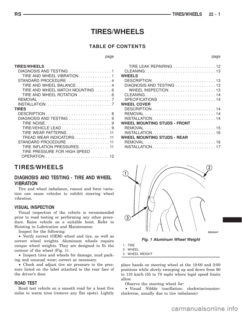
contour of the wheel (Fig. 1).
²Inspect tires and wheels for damage, mud pack-
ing and unusual wear; correct as necessary.
²Check and adjust tire air pressure to the pres-
sure listed on the label attached to the rear face of
the driver's door.
ROAD TEST
Road test vehicle on a smooth road for a least five
miles to warm tires (remove any flat spots). Lightlyplace hands on steering wheel at the 10:00 and 2:00
positions while slowly sweeping up and down from 90
to 110 km/h (55 to 70 mph) where legal speed limits
allow.
Observe the steering wheel for:
²Visual Nibble (oscillation: clockwise/counter-
clockwise, usually due to tire imbalance)
Fig. 1 Aluminum Wheel Weight
1 - TIRE
2 - WHEEL
3 - WHEEL WEIGHT
RSTIRES/WHEELS22-1
Page 3370 of 4284

(3) Place the wheel cover on the wheel in the fol-
lowing fashion:
(a) Align the valve notch in the wheel cover with
the valve stem on the wheel.
(b) At the same time, align the two holes in the
wheel cover having the retaining tabs with the two
installed wheel nuts (Fig. 15).
(c) Press in on center of wheel cover until wheel
cover retaining tabs push past and engage rear of
previously installed wheel mounting nuts (Fig. 15).
This will hold the wheel cover in place.(4) Install andlightly tightenthe three remain-
ing wheel mounting nuts, securing the wheel cover in
place (Fig. 12).
(5) Progressively tighten all five wheel mounting
nuts in the proper sequence (Fig. 16). Tighten wheel
nuts to a torque of 135 N´m (100 ft. lbs.).
(6) Lower the vehicle.
TIRES
DESCRIPTION - TIRE
Tires are designed and engineered for each specific
vehicle. They provide the best overall performance
for normal operation. The ride and handling charac-
teristics match the vehicle's requirements. With
proper care they will give excellent reliability, trac-
tion, skid resistance, and tread life.
Driving habits have more effect on tire life than
any other factor. Careful drivers will obtain, in most
cases, much greater mileage than severe use or care-
less drivers. A few of the driving habits which will
shorten the life of any tire are:
²Rapid acceleration
²Severe application of brakes
²High-speed driving
²Taking turns at excessive speeds
²Striking curbs and other obstacles
²Operating vehicle with over or under inflated
tire pressures
Radial ply tires are more prone to irregular tread
wear. It is important to follow the tire rotation inter-
val shown in the section on Tire Rotation. This will
help to achieve a greater tread-life potential.
TIRE IDENTIFICATION
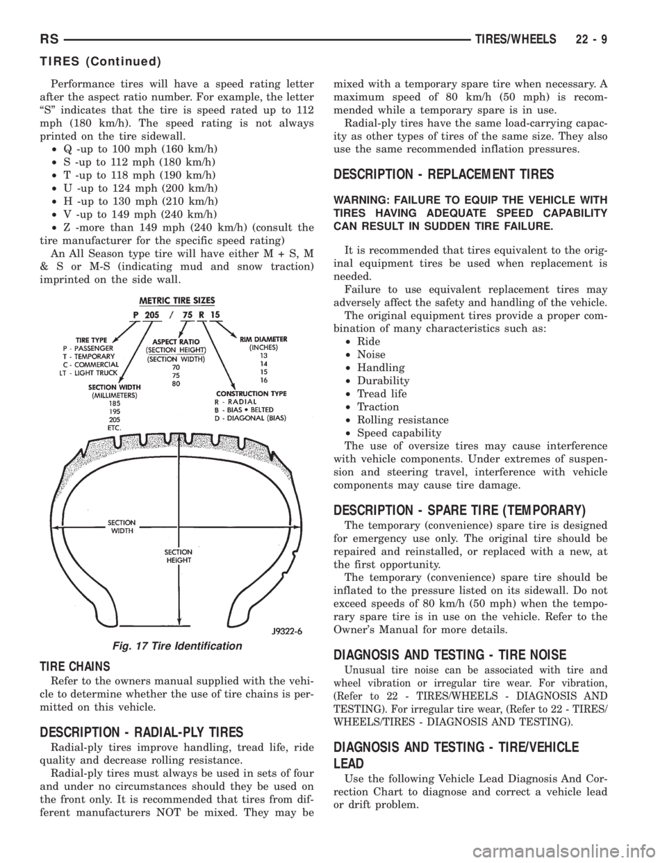
Tire type, size, aspect ratio and speed rating are
encoded in the letters and numbers imprinted on the
side wall of the tire. Refer to the chart to decipher
the tire identification code (Fig. 17).
Fig. 14 TWO WHEEL MOUNTING NUTS INSTALLED
1 - WHEEL
2 - VALVE STEM
3 - HUB PILOT
4 - NUTS
Fig. 15 WHEEL COVER INSTALLATION OVER TWO
NUTS
1 - RETAINING TABS
2 - VALVE STEM
3 - BOLT-ON WHEEL COVER
Fig. 16 NUT TIGHTENING SEQUENCE
22 - 8 TIRES/WHEELSRS
TIRES/WHEELS (Continued)
Page 3371 of 4284
Performance tires will have a speed rating letter
after the aspect ratio number. For example, the letter
ªSº indicates that the tire is speed rated up to 112
mph (180 km/h). The speed rating is not always
printed on the tire sidewall.
²Q -up to 100 mph (160 km/h)
²S -up to 112 mph (180 km/h)
²T -up to 118 mph (190 km/h)
²U -up to 124 mph (200 km/h)
²H -up to 130 mph (210 km/h)
²V -up to 149 mph (240 km/h)
²Z -more than 149 mph (240 km/h) (consult the
tire manufacturer for the specific speed rating)
An All Season type tire will have eitherM+S,M
& S or M-S (indicating mud and snow traction)
imprinted on the side wall.
TIRE CHAINS
Refer to the owners manual supplied with the vehi-
cle to determine whether the use of tire chains is per-
mitted on this vehicle.
DESCRIPTION - RADIAL-PLY TIRES
Radial-ply tires improve handling, tread life, ride
quality and decrease rolling resistance.
Radial-ply tires must always be used in sets of four
and under no circumstances should they be used on
the front only. It is recommended that tires from dif-
ferent manufacturers NOT be mixed. They may bemixed with a temporary spare tire when necessary. A
maximum speed of 80 km/h (50 mph) is recom-
mended while a temporary spare is in use.
Radial-ply tires have the same load-carrying capac-
ity as other types of tires of the same size. They also
use the same recommended inflation pressures.
DESCRIPTION - REPLACEMENT TIRES
WARNING: FAILURE TO EQUIP THE VEHICLE WITH
TIRES HAVING ADEQUATE SPEED CAPABILITY
CAN RESULT IN SUDDEN TIRE FAILURE.
It is recommended that tires equivalent to the orig-
inal equipment tires be used when replacement is
needed.
Failure to use equivalent replacement tires may
adversely affect the safety and handling of the vehicle.
The original equipment tires provide a proper com-
bination of many characteristics such as:
²Ride
²Noise
²Handling
²Durability
²Tread life
²Traction
²Rolling resistance
²Speed capability
The use of oversize tires may cause interference
with vehicle components. Under extremes of suspen-
sion and steering travel, interference with vehicle
components may cause tire damage.
DESCRIPTION - SPARE TIRE (TEMPORARY)
The temporary (convenience) spare tire is designed
for emergency use only. The original tire should be
repaired and reinstalled, or replaced with a new, at
the first opportunity.
The temporary (convenience) spare tire should be
inflated to the pressure listed on its sidewall. Do not
exceed speeds of 80 km/h (50 mph) when the tempo-
rary spare tire is in use on the vehicle. Refer to the
Owner's Manual for more details.
DIAGNOSIS AND TESTING - TIRE NOISE
Unusual tire noise can be associated with tire and
wheel vibration or irregular tire wear. For vibration,
(Refer to 22 - TIRES/WHEELS - DIAGNOSIS AND
TESTING). For irregular tire wear, (Refer to 22 - TIRES/
WHEELS/TIRES - DIAGNOSIS AND TESTING).
DIAGNOSIS AND TESTING - TIRE/VEHICLE
LEAD
Use the following Vehicle Lead Diagnosis And Cor-
rection Chart to diagnose and correct a vehicle lead
or drift problem.
Fig. 17 Tire Identification
RSTIRES/WHEELS22-9
TIRES (Continued)
Page 3373 of 4284
DIAGNOSIS AND TESTING - TIRE WEAR
PATTERNS
Under inflation will cause wear on the shoulders of
tire. Over inflation will cause wear at the center of
tire.
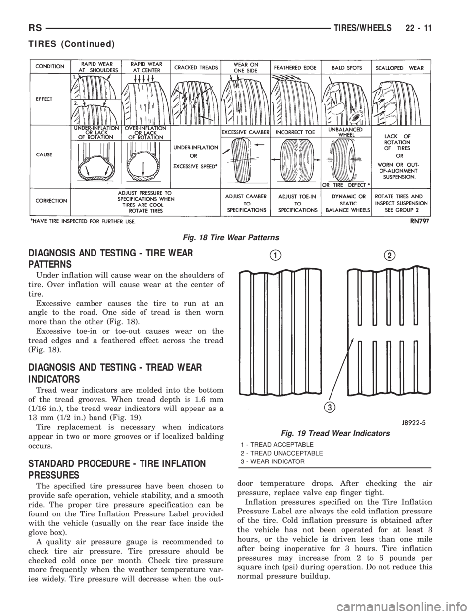
Excessive camber causes the tire to run at an
angle to the road. One side of tread is then worn
more than the other (Fig. 18).
Excessive toe-in or toe-out causes wear on the
tread edges and a feathered effect across the tread
(Fig. 18).
DIAGNOSIS AND TESTING - TREAD WEAR
INDICATORS
Tread wear indicators are molded into the bottom
of the tread grooves. When tread depth is 1.6 mm
(1/16 in.), the tread wear indicators will appear as a
13 mm (1/2 in.) band (Fig. 19).
Tire replacement is necessary when indicators
appear in two or more grooves or if localized balding
occurs.
STANDARD PROCEDURE - TIRE INFLATION
PRESSURES
The specified tire pressures have been chosen to
provide safe operation, vehicle stability, and a smooth
ride. The proper tire pressure specification can be
found on the Tire Inflation Pressure Label provided
with the vehicle (usually on the rear face inside the
glove box).
A quality air pressure gauge is recommended to
check tire air pressure. Tire pressure should be
checked cold once per month. Check tire pressure
more frequently when the weather temperature var-
ies widely. Tire pressure will decrease when the out-door temperature drops. After checking the air
pressure, replace valve cap finger tight.
Inflation pressures specified on the Tire Inflation
Pressure Label are always the cold inflation pressure
of the tire. Cold inflation pressure is obtained after
the vehicle has not been operated for at least 3
hours, or the vehicle is driven less than one mile
after being inoperative for 3 hours. Tire inflation
pressures may increase from 2 to 6 pounds per
square inch (psi) during operation. Do not reduce this
normal pressure buildup.
Fig. 18 Tire Wear Patterns
Fig. 19 Tread Wear Indicators
1 - TREAD ACCEPTABLE
2 - TREAD UNACCEPTABLE
3 - WEAR INDICATOR
RSTIRES/WHEELS22-11
TIRES (Continued)
Page 3374 of 4284
Improper inflation can cause:
²Uneven wear patterns
²Reduced tread life
²Reduced fuel economy
²Unsatisfactory ride
²The vehicle to drift.
WARNING: OVER OR UNDER INFLATED TIRES CAN
AFFECT VEHICLE HANDLING. THE TIRE CAN FAIL
SUDDENLY, RESULTING IN LOSS OF VEHICLE
CONTROL.
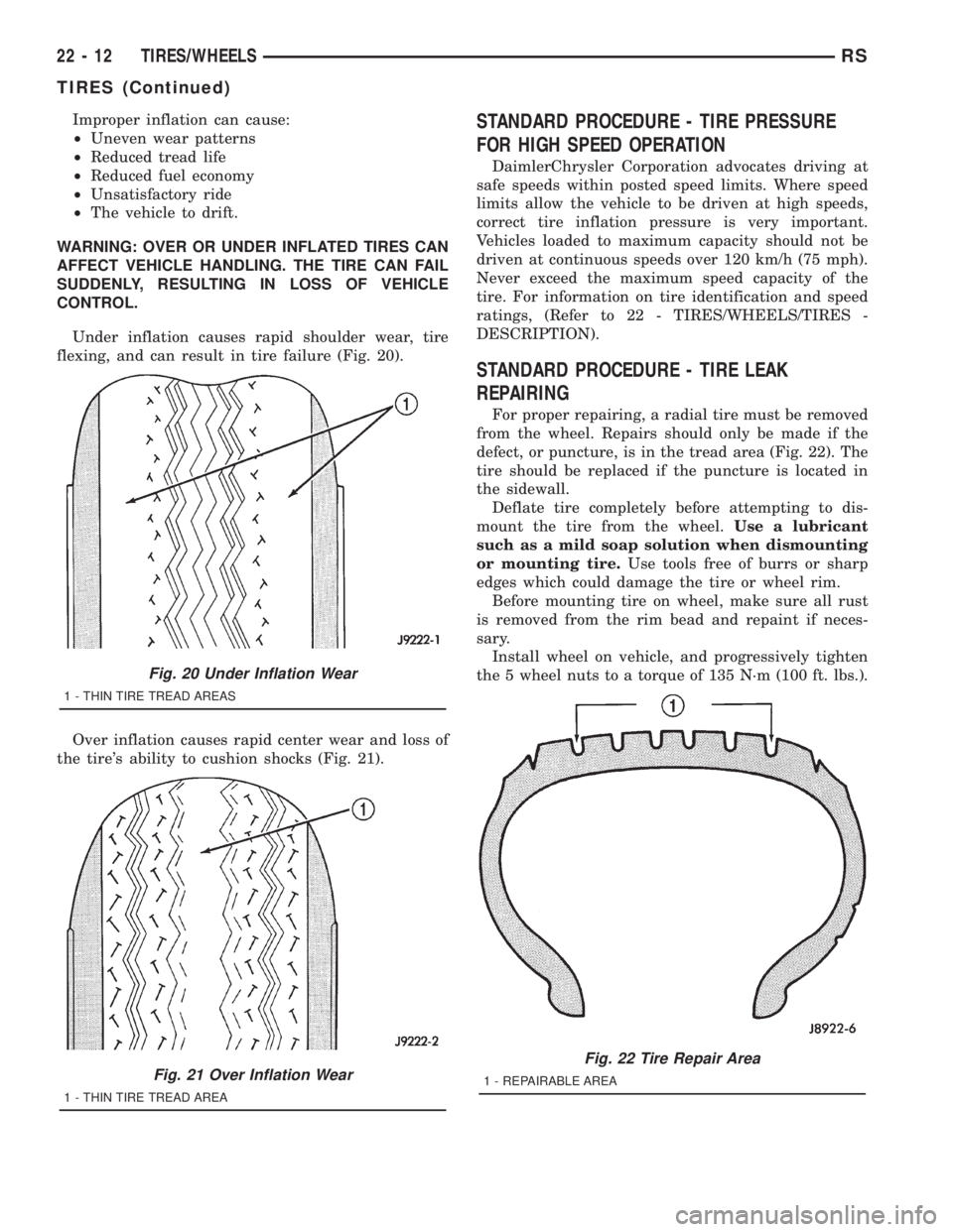
Under inflation causes rapid shoulder wear, tire
flexing, and can result in tire failure (Fig. 20).
Over inflation causes rapid center wear and loss of
the tire's ability to cushion shocks (Fig. 21).STANDARD PROCEDURE - TIRE PRESSURE
FOR HIGH SPEED OPERATION
DaimlerChrysler Corporation advocates driving at
safe speeds within posted speed limits. Where speed
limits allow the vehicle to be driven at high speeds,
correct tire inflation pressure is very important.
Vehicles loaded to maximum capacity should not be
driven at continuous speeds over 120 km/h (75 mph).
Never exceed the maximum speed capacity of the
tire. For information on tire identification and speed
ratings, (Refer to 22 - TIRES/WHEELS/TIRES -
DESCRIPTION).
STANDARD PROCEDURE - TIRE LEAK
REPAIRING
For proper repairing, a radial tire must be removed
from the wheel. Repairs should only be made if the
defect, or puncture, is in the tread area (Fig. 22). The
tire should be replaced if the puncture is located in
the sidewall.
Deflate tire completely before attempting to dis-
mount the tire from the wheel.Use a lubricant
such as a mild soap solution when dismounting
or mounting tire.Use tools free of burrs or sharp
edges which could damage the tire or wheel rim.
Before mounting tire on wheel, make sure all rust
is removed from the rim bead and repaint if neces-
sary.
Install wheel on vehicle, and progressively tighten
the 5 wheel nuts to a torque of 135 N´m (100 ft. lbs.).
Fig. 20 Under Inflation Wear
1 - THIN TIRE TREAD AREAS
Fig. 21 Over Inflation Wear
1 - THIN TIRE TREAD AREA
Fig. 22 Tire Repair Area
1 - REPAIRABLE AREA
22 - 12 TIRES/WHEELSRS
TIRES (Continued)
Page 3375 of 4284

CLEANING - TIRES
Before delivery of a vehicle, remove the protective
coating on the tires with white sidewalls or raised
white letters. To remove the protective coating, apply
warm water and let it soak for a few minutes. After-
wards, scrub the coating away with a soft bristle
brush. Steam cleaning may also be used to remove
the coating.
CAUTION: DO NOT use gasoline, mineral oil, oil-
based solvent or a wire brush for cleaning.
WHEELS
DESCRIPTION - WHEEL
Original equipment wheels are designed for proper
operation at all loads up to the specified maximum
vehicle capacity.
All models use either steel or aluminum drop-cen-
ter wheels. Every wheel has raised sections between
the rim flanges and rim drop well called safety
humps (Fig. 23). Initial inflation of the tires forces
the bead over these raised sections. In case of air
loss, the safety humps hold the tire in position on the
wheel until the vehicle can be brought to a safe stop.
Cast aluminum wheels require special balance
weights to fit on the flange of the rim (Fig. 24).
When wheel alignment is necessary on a vehicle
with cast aluminum wheels, special wheel clamps are
required to avoid damage to the wheel's finish.The wheel studs and nuts are designed for specific
wheel applications and must be replaced with equiv-
alent parts.
All aluminum wheels have wheel mounting (lug)
nuts with an enlarged nose. This enlarged nose is
necessary to ensure proper retention of the wheels.
DIAGNOSIS AND TESTING - WHEEL
INSPECTION
Inspect wheels for:
²Excessive runout
²Dents, cracks or irregular bends
²Damaged wheel stud (lug) holes
²Air Leaks
NOTE: Do not attempt to repair a wheel by hammer-
ing, heating or welding.
If a wheel is damaged, an original equipment
replacement wheel should be used. When obtaining
replacement wheels, they should be equivalent in
load carrying capacity. The diameter, width, offset,
pilot hole and bolt circle of the wheel should be the
same as the original wheel.
WARNING: FAILURE TO USE EQUIVALENT
REPLACEMENT WHEELS MAY ADVERSELY
AFFECT THE SAFETY AND HANDLING OF THE
VEHICLE.
WARNING: REPLACEMENT WITH USED WHEELS IS
NOT RECOMMENDED. THE SERVICE HISTORY OF
THE WHEEL MAY HAVE INCLUDED SEVERE TREAT-
MENT OR VERY HIGH MILEAGE. THE RIM COULD
FAIL WITHOUT WARNING.
Fig. 23 Safety Rim
1 - TIRE
2 - WELL
3 - SAFETY HUMPS
4 - FLANGE
Fig. 24 Styled Aluminum Wheel Weight
1 - TIRE
2 - WHEEL
3 - STYLED WHEEL WEIGHT
RSTIRES/WHEELS22-13
TIRES (Continued)
Page 3378 of 4284
INSTALLATION
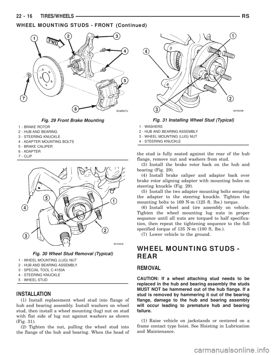
(1) Install replacement wheel stud into flange of
hub and bearing assembly. Install washers on wheel
stud, then install a wheel mounting (lug) nut on stud
with flat side of lug nut against washers as shown
(Fig. 31).
(2) Tighten the nut, pulling the wheel stud into
the flange of the hub and bearing. When the head ofthe stud is fully seated against the rear of the hub
flange, remove nut and washers from stud.
(3) Install the brake rotor back on the hub and
bearing (Fig. 29).
(4) Install brake caliper and adapter back over
brake rotor aligning adapter with mounting holes on
steering knuckle (Fig. 29).
(5) Install the two adapter mounting bolts securing
the adapter to the steering knuckle. Tighten the
mounting bolts to 169 N´m (125 ft. lbs.) torque.
(6) Install wheel and tire assembly on vehicle.
Tighten the wheel mounting lug nuts in proper
sequence until all nuts are torqued to half specifica-
tion, then repeat the tightening sequence to the full
specified torque of 135 N´m (100 ft. lbs.).
(7) Lower vehicle to the ground.
WHEEL MOUNTING STUDS -
REAR
REMOVAL
CAUTION: If a wheel attaching stud needs to be
replaced in the hub and bearing assembly the studs
MUST NOT be hammered out of the hub flange. If a
stud is removed by hammering it out of the bearing
flange, damage to the hub and bearing assembly
will occur leading to premature hub and bearing
failure.
(1) Raise vehicle on jackstands or centered on a
frame contact type hoist. See Hoisting in Lubrication
and Maintenance.
Fig. 29 Front Brake Mounting
1 - BRAKE ROTOR
2 - HUB AND BEARING
3 - STEERING KNUCKLE
4 - ADAPTER MOUNTING BOLTS
5 - BRAKE CALIPER
6 - ADAPTER
7 - CLIP
Fig. 30 Wheel Stud Removal (Typical)
1 - WHEEL MOUNTING (LUG) NUT
2 - HUB AND BEARING ASSEMBLY
3 - SPECIAL TOOL C-4150A
4 - STEERING KNUCKLE
5 - WHEEL STUD
Fig. 31 Installing Wheel Stud (Typical)
1 - WASHERS
2 - HUB AND BEARING ASSEMBLY
3 - WHEEL MOUNTING (LUG) NUT
4 - STEERING KNUCKLE
22 - 16 TIRES/WHEELSRS
WHEEL MOUNTING STUDS - FRONT (Continued)
Page 3379 of 4284
(2) Remove the rear wheel and tire assembly.
(3) Remove the brake drum or disc brake caliper
and rotor. Refer to Brakes.
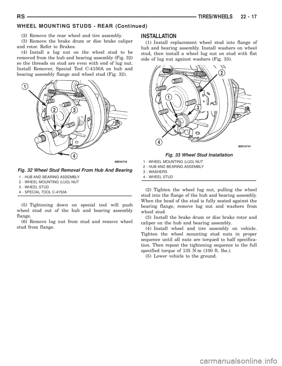
(4) Install a lug nut on the wheel stud to be
removed from the hub and bearing assembly (Fig. 32)
so the threads on stud are even with end of lug nut.
Install Remover, Special Tool C-4150A on hub and
bearing assembly flange and wheel stud (Fig. 32).
(5) Tightening down on special tool will push
wheel stud out of the hub and bearing assembly
flange.
(6) Remove lug nut from stud and remove wheel
stud from flange.INSTALLATION
(1) Install replacement wheel stud into flange of
hub and bearing assembly. Install washers on wheel
stud, then install a wheel lug nut on stud with flat
side of lug nut against washers (Fig. 33).
(2) Tighten the wheel lug nut, pulling the wheel
stud into the flange of the hub and bearing assembly.
When the head of the stud is fully seated against the
bearing flange, remove lug nut and washers from
wheel stud.
(3) Install the brake drum or disc brake rotor and
caliper on the hub and bearing assembly.
(4) Install wheel and tire assembly on vehicle.
Tighten the wheel mounting stud nuts in proper
sequence until all nuts are torqued to half specifica-
tion. Then repeat the tightening sequence to the full
specified torque of 135 N´m (100 ft. lbs.).
(5) Lower vehicle to the ground.
Fig. 32 Wheel Stud Removal From Hub And Bearing
1 - HUB AND BEARING ASSEMBLY
2 - WHEEL MOUNTING (LUG) NUT
3 - WHEEL STUD
4 - SPECIAL TOOL C-4150A
Fig. 33 Wheel Stud Installation
1 - WHEEL MOUNTING (LUG) NUT
2 - HUB AND BEARING ASSEMBLY
3 - WASHERS
4 - WHEEL STUD
RSTIRES/WHEELS22-17
WHEEL MOUNTING STUDS - REAR (Continued)