clutch CHRYSLER VOYAGER 2001 Service Manual
[x] Cancel search | Manufacturer: CHRYSLER, Model Year: 2001, Model line: VOYAGER, Model: CHRYSLER VOYAGER 2001Pages: 4284, PDF Size: 83.53 MB
Page 3247 of 4284

STATOR
The stator assembly (Fig. 334) is mounted on a sta-
tionary shaft which is an integral part of the oil
pump. The stator is located between the impeller and
turbine within the torque converter case (Fig. 335).
The stator contains an over-running clutch, which
allows the stator to rotate only in a clockwise direc-
tion. When the stator is locked against the over-run-
ning clutch, the torque multiplication feature of the
torque converter is operational.
TORQUE CONVERTER CLUTCH (TCC)
The TCC (Fig. 336) was installed to improve the
efficiency of the torque converter that is lost to the
slippage of the fluid coupling. Although the fluid cou-
pling provides smooth, shock±free power transfer, it
is natural for all fluid couplings to slip. If the impel-
ler and turbine were mechanically locked together, a
zero slippage condition could be obtained. A hydraulic
piston was added to the turbine, and a friction mate-
rial was added to the inside of the front cover to pro-
vide this mechanical lock-up.
Fig. 333 Turbine
1 - TURBINE VANE
2 - ENGINE ROTATION
3 - INPUT SHAFT
4 - PORTION OF TORQUE CONVERTER COVER5 - ENGINE ROTATION
6 - OIL FLOW WITHIN TURBINE SECTION
RSAUTOMATIC - 41TE21 - 283
TORQUE CONVERTER (Continued)
Page 3248 of 4284

OPERATION
The converter impeller (Fig. 337) (driving member),
which is integral to the converter housing and bolted
to the engine drive plate, rotates at engine speed.
The converter turbine (driven member), which reacts
from fluid pressure generated by the impeller, rotates
and turns the transmission input shaft.
TURBINE
As the fluid that was put into motion by the impel-
ler blades strikes the blades of the turbine, some of
the energy and rotational force is transferred into the
turbine and the input shaft. This causes both of them
(turbine and input shaft) to rotate in a clockwise
direction following the impeller. As the fluid is leav-
ing the trailing edges of the turbine's blades it con-
tinues in a ªhinderingº direction back toward the
impeller. If the fluid is not redirected before it strikes
the impeller, it will strike the impeller in such a
direction that it would tend to slow it down.
Fig. 334 Stator Components
1 - CAM (OUTER RACE)
2 - ROLLER
3 - SPRING
4 - INNER RACE
Fig. 335 Stator Location
1-STATOR
2 - IMPELLER
3 - FLUID FLOW
4 - TURBINE
Fig. 336 Torque Converter Clutch (TCC)
1 - IMPELLER FRONT COVER
2 - THRUST WASHER ASSEMBLY
3 - IMPELLER
4-STATOR
5 - TURBINE
6 - PISTON
7 - FRICTION DISC
21 - 284 AUTOMATIC - 41TERS
TORQUE CONVERTER (Continued)
Page 3249 of 4284

STATOR
Torque multiplication is achieved by locking the
stator's over-running clutch to its shaft (Fig. 338).
Under stall conditions (the turbine is stationary), the
oil leaving the turbine blades strikes the face of the
stator blades and tries to rotate them in a counter-
clockwise direction. When this happens the over±run-
ning clutch of the stator locks and holds the stator
from rotating. With the stator locked, the oil strikes
the stator blades and is redirected into a ªhelpingº
direction before it enters the impeller. This circula-
tion of oil from impeller to turbine, turbine to stator,
and stator to impeller, can produce a maximum
torque multiplication of about 2.4:1. As the turbine
begins to match the speed of the impeller, the fluid
that was hitting the stator in such as way as to
cause it to lock±up is no longer doing so. In this con-
dition of operation, the stator begins to free wheel
and the converter acts as a fluid coupling.
TORQUE CONVERTER CLUTCH (TCC)
In a standard torque converter, the impeller and
turbine are rotating at about the same speed and the
stator is freewheeling, providing no torque multipli-
cation. By applying the turbine's piston to the front
cover's friction material, a total converter engage-ment can be obtained. The result of this engagement
is a direct 1:1 mechanical link between the engine
and the transmission.
Fig. 337 Torque Converter Fluid Operation
1 - APPLY PRESSURE
2 - THE PISTON MOVES SLIGHTLY FORWARD3 - RELEASE PRESSURE
4 - THE PISTON MOVES SLIGHTLY REARWARD
Fig. 338 Stator Operation
1 - DIRECTION STATOR WILL FREE WHEEL DUE TO OIL
PUSHING ON BACKSIDE OF VANES
2 - FRONT OF ENGINE
3 - INCREASED ANGLE AS OIL STRIKES VANES
4 - DIRECTION STATOR IS LOCKED UP DUE TO OIL PUSHING
AGAINST STATOR VANES
RSAUTOMATIC - 41TE21 - 285
TORQUE CONVERTER (Continued)
Page 3250 of 4284
The engagement and disengagement of the TCC
are automatic and controlled by the Powertrain Con-
trol Module (PCM). The engagement cannot be acti-
vated in the lower gears because it eliminates the
torque multiplication effect of the torque converter
necessary for acceleration. Inputs that determine
clutch engagement are: coolant temperature, vehicle
speed and throttle position. The torque converter
clutch is engaged by the clutch solenoid on the valve
body. The clutch will engage at approximately 56
km/h (35 mph) with light throttle, after the shift to
third gear.
REMOVAL
NOTE: If torque conveter assembly is being
replaced, it is necessary to restart the TCC Break-In
Strategy. (Refer to 8 - ELECTRICAL/ELECTRONIC
CONTROL MODULES/TRANSMISSION CONTROL
MODULE - STANDARD PROCEDURE)
(1) Remove transmission and torque converter
from vehicle. (Refer to 21 - TRANSMISSION/TRANS-
AXLE/AUTOMATIC - 41TE - REMOVAL)
(2) Place a suitable drain pan under the converter
housing end of the transmission.
CAUTION: Verify that transmission is secure on the
lifting device or work surface, the center of gravity
of the transmission will shift when the torque con-
verter is removed creating an unstable condition.
The torque converter is a heavy unit. Use caution
when separating the torque converter from the
transmission.
(3) Pull the torque converter forward until the cen-
ter hub clears the oil pump seal.
(4) Separate the torque converter from the trans-
mission.
INSTALLATION
NOTE: If torque conveter is being replaced, it is
necessary to restart the TCC Break-In Strategy.
(Refer to 8 - ELECTRICAL/ELECTRONIC CONTROL
MODULES/TRANSMISSION CONTROL MODULE -
STANDARD PROCEDURE)
Check converter hub and drive notches for sharp
edges, burrs, scratches, or nicks. Polish the hub and
notches with 320/400 grit paper or crocus cloth if nec-
essary. The hub must be smooth to avoid damaging
the pump seal at installation.
(1) Lubricate converter hub and oil pump seal lip
with transmission fluid.
(2) Place torque converter in position on transmis-
sion.CAUTION: Do not damage oil pump seal or bushing
while inserting torque converter into the front of the
transmission.
(3) Align torque converter to oil pump seal open-
ing.
(4) Insert torque converter hub into oil pump.
(5) While pushing torque converter inward, rotate
converter until converter is fully seated in the oil
pump gears.
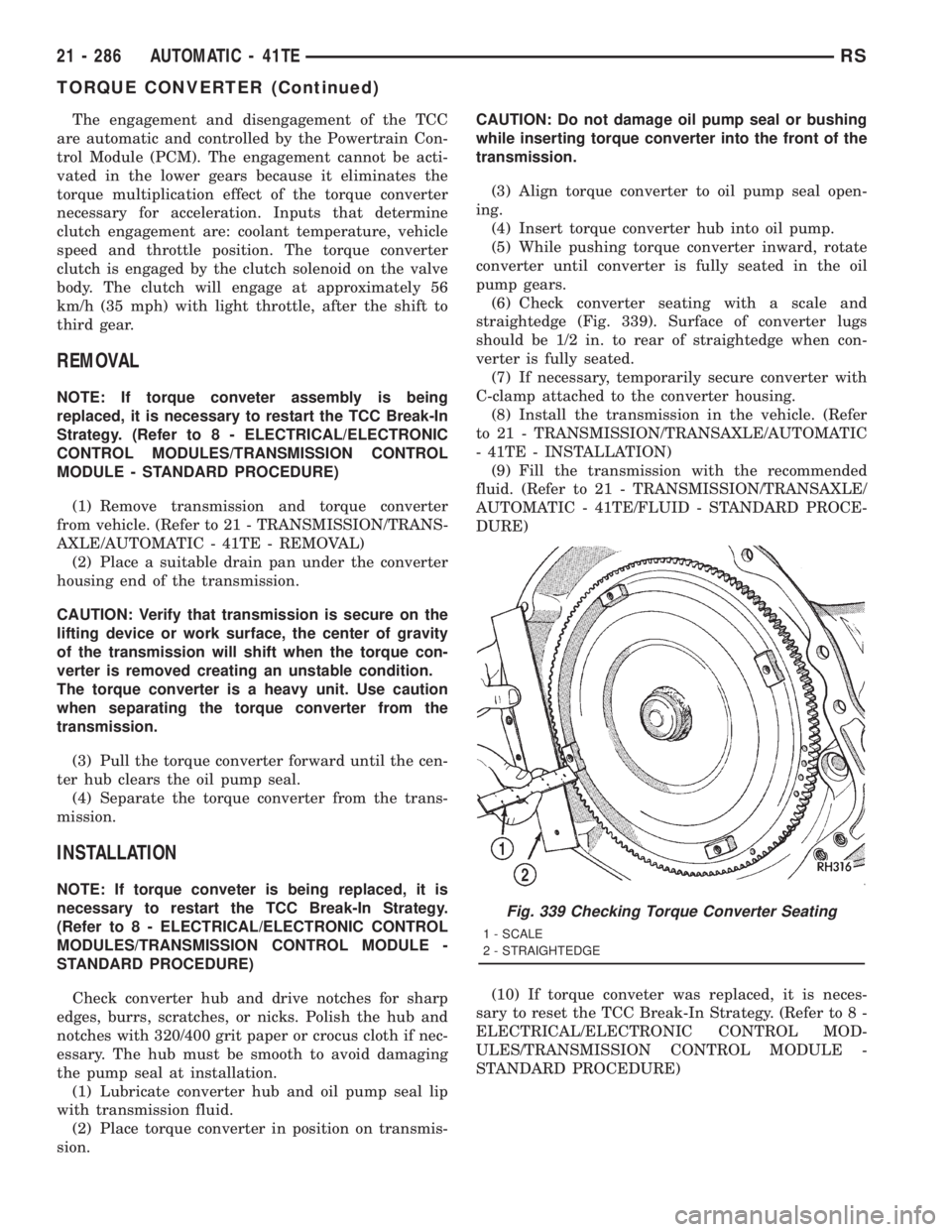
(6) Check converter seating with a scale and
straightedge (Fig. 339). Surface of converter lugs
should be 1/2 in. to rear of straightedge when con-
verter is fully seated.
(7) If necessary, temporarily secure converter with
C-clamp attached to the converter housing.
(8) Install the transmission in the vehicle. (Refer
to 21 - TRANSMISSION/TRANSAXLE/AUTOMATIC
- 41TE - INSTALLATION)
(9) Fill the transmission with the recommended
fluid. (Refer to 21 - TRANSMISSION/TRANSAXLE/
AUTOMATIC - 41TE/FLUID - STANDARD PROCE-
DURE)
(10) If torque conveter was replaced, it is neces-
sary to reset the TCC Break-In Strategy. (Refer to 8 -
ELECTRICAL/ELECTRONIC CONTROL MOD-
ULES/TRANSMISSION CONTROL MODULE -
STANDARD PROCEDURE)
Fig. 339 Checking Torque Converter Seating
1 - SCALE
2 - STRAIGHTEDGE
21 - 286 AUTOMATIC - 41TERS
TORQUE CONVERTER (Continued)
Page 3253 of 4284
TORQUE REDUCTION LINK
(TRD)
DESCRIPTION
The Torque Reduction Link (TRD) is a wire
between the PCM and TCM that is used by the TCM
to request torque management. Torque management
controls or reduces torque output of the engine dur-
ing certain shift sequences, reducing torque applied
to the transaxle clutches.
OPERATION
The torque management signal is basically a
12-volt pull-up supplied by the PCM to the TCM over
the torque reduction link (TRD). Torque management
is requested when the TCM pulses this signal to
ground. The PCM recognizes this request and
responds by retarding ignition timing, killing fuel
injectors, etc. The PCM sends a confirmation of the
request to the TCM via the communication bus.
Torque reduction is not noticable by the driver, and
usually lasts for a very short period of time.
If the confirmation signal is not received by the
TCM after two sequential request messages, a diag-
nostic trouble code will be set.
VALVE BODY
DESCRIPTION
The valve body assembly consists of a cast alumi-
num valve body, a separator plate, and transfer
plate. The valve body contains valves and check balls
that control fluid delivery to the torque converter
clutch, solenoid/pressure switch assembly, and fric-
tional clutches. The valve body contains the following
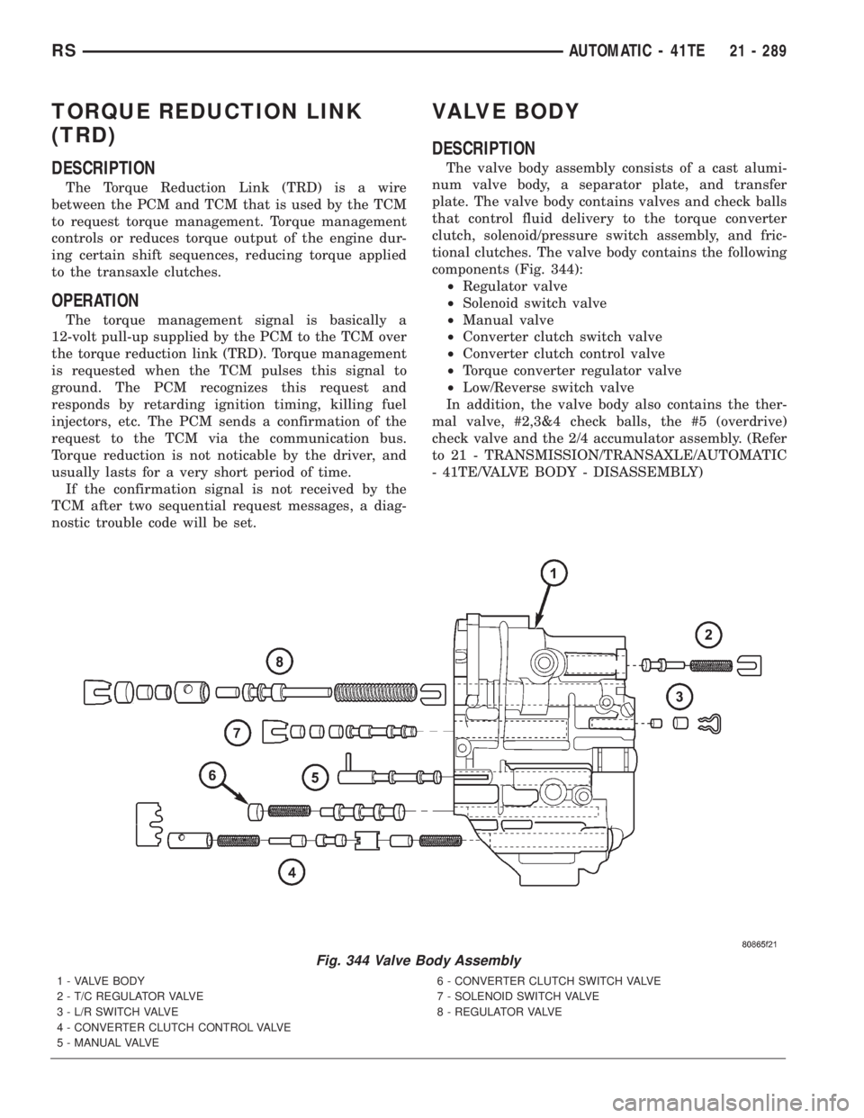
components (Fig. 344):
²Regulator valve
²Solenoid switch valve
²Manual valve
²Converter clutch switch valve
²Converter clutch control valve
²Torque converter regulator valve
²Low/Reverse switch valve
In addition, the valve body also contains the ther-
mal valve, #2,3&4 check balls, the #5 (overdrive)
check valve and the 2/4 accumulator assembly. (Refer
to 21 - TRANSMISSION/TRANSAXLE/AUTOMATIC
- 41TE/VALVE BODY - DISASSEMBLY)
Fig. 344 Valve Body Assembly
1 - VALVE BODY
2 - T/C REGULATOR VALVE
3 - L/R SWITCH VALVE
4 - CONVERTER CLUTCH CONTROL VALVE
5 - MANUAL VALVE6 - CONVERTER CLUTCH SWITCH VALVE
7 - SOLENOID SWITCH VALVE
8 - REGULATOR VALVE
RSAUTOMATIC - 41TE21 - 289
Page 3254 of 4284
OPERATION
NOTE: Refer to the Hydraulic Schematics for a
visual aid in determining valve location, operation
and design.
REGULATOR VALVE
The regulator valve controls hydraulic pressure in
the transaxle. It receives unregulated pressure from
the pump, which works against spring tension to
maintain oil at specific pressures. A system of sleeves
and ports allows the regulator valve to work at one of
three predetermined pressure levels. Regulated oil
pressure is also referred to as ªline pressure.º
SOLENOID SWITCH VALVE
The solenoid switch valve controls line pressure
from the LR/CC solenoid. In one position, it allows
the low/reverse clutch to be pressurized. In the other,
it directs line pressure to the converter control and
converter clutch valves.
MANUAL VALVE
The manual valve is operated by the mechanical
shift linkage. Its primary responsibility is to send
line pressure to the appropriate hydraulic circuits
and solenoids. The valve has three operating ranges
or positions.
CONVERTER CLUTCH SWITCH VALVE
The main responsibility of the converter clutch
switch valve is to control hydraulic pressure applied
to the front (off) side of the converter clutch piston.
Line pressure from the regulator valve is fed to the
torque converter regulator valve, where it passes
through the valve, and is slightly regulated. The
pressure is then directed to the converter clutch
switch valve and to the front side of the converter
clutch piston. This pressure pushes the piston back
and disengages the converter clutch.
CONVERTER CLUTCH CONTROL VALVE
The converter clutch control valve controls the
back (on) side of the torque converter clutch. When
the TCM energizes or modulates the LR/CC solenoid
to apply the converter clutch piston, both the con-
verter clutch control valve and the converter control
valve move, allowing pressure to be applied to the
back side of the clutch.
T/C REGULATOR VALVE
The torque converter regulator valve slightly regu-
lates the flow of fluid to the torque converter.
LOW/REVERSE SWITCH VALVE
The low/reverse clutch is applied from different
sources, depending on whether low (1st) gear or
reverse is selected. The low/reverse switch valve
alternates positions depending on from which direc-
tion fluid pressure is applied. By design, when the
valve is shifted by fluid pressure from one channel,
the opposing channel is blocked. The switch valve
alienates the possibility of a sticking ball check, thus
providing consistent application of the low/reverse
clutch under all operating conditions.
REMOVAL
NOTE: If valve body is replaced or reconditioned,
the TCM Quick Learn Procedure must be per-
formed. (Refer to 8 - ELECTRICAL/ELECTRONIC
CONTROL MODULES/TRANSMISSION CONTROL
MODULE - STANDARD PROCEDURE)
(1) Disconnect battery negative cable.
(2) Disconnect gearshift cable from manual valve
lever.
(3) Remove manual valve lever from manual shaft.
(4) Raise vehicle on hoist.
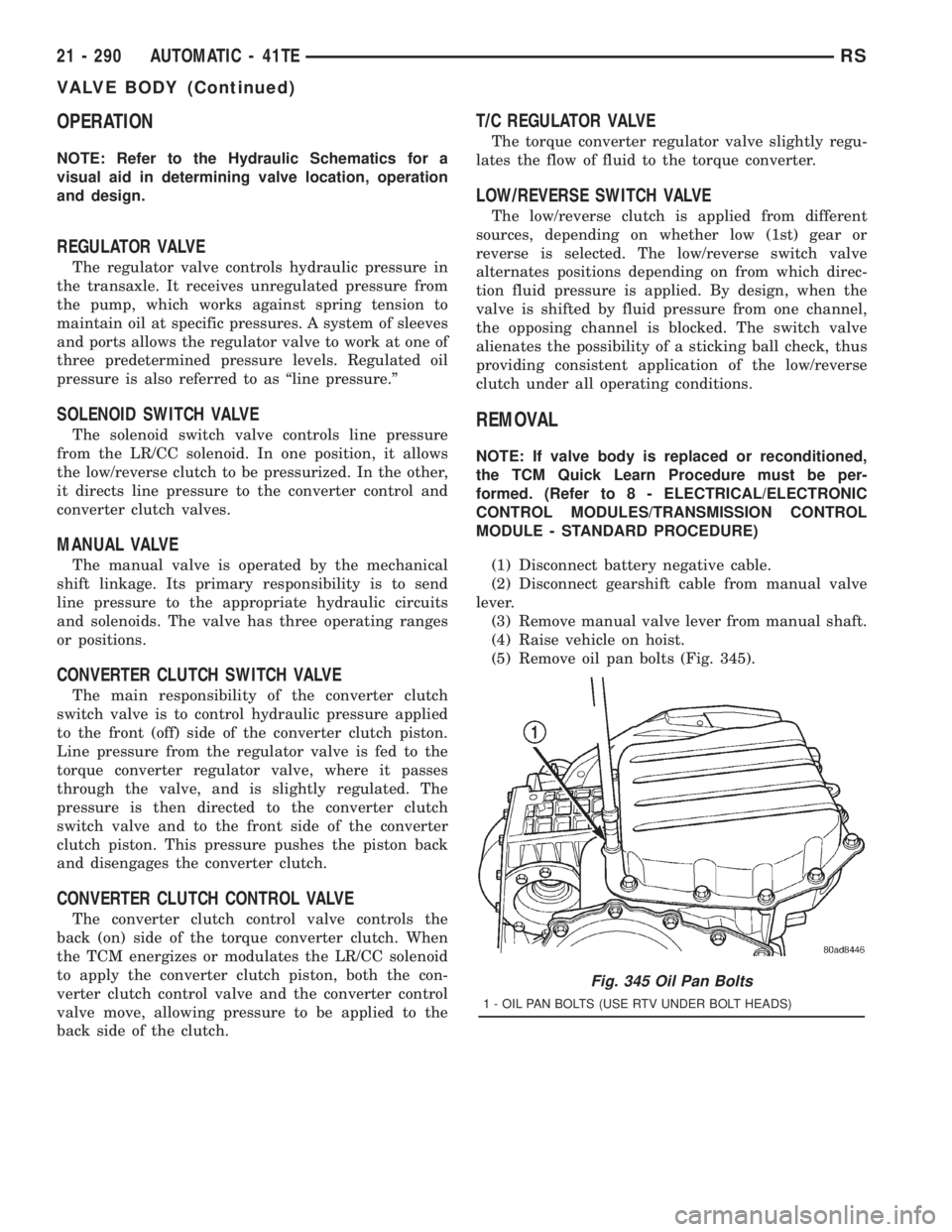
(5) Remove oil pan bolts (Fig. 345).
Fig. 345 Oil Pan Bolts
1 - OIL PAN BOLTS (USE RTV UNDER BOLT HEADS)
21 - 290 AUTOMATIC - 41TERS
VALVE BODY (Continued)
Page 3258 of 4284
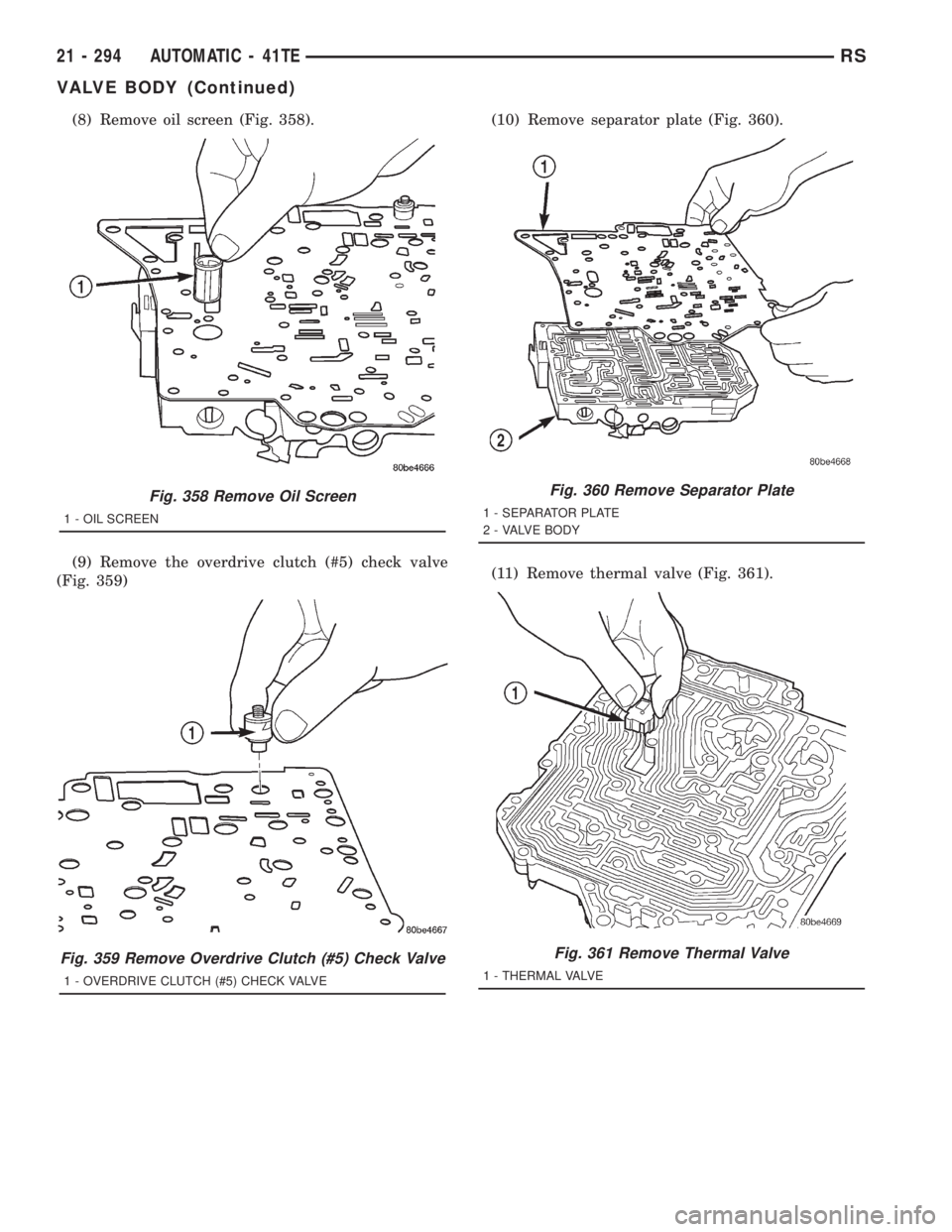
(8) Remove oil screen (Fig. 358).
(9) Remove the overdrive clutch (#5) check valve
(Fig. 359)(10) Remove separator plate (Fig. 360).
(11) Remove thermal valve (Fig. 361).
Fig. 358 Remove Oil Screen
1 - OIL SCREEN
Fig. 359 Remove Overdrive Clutch (#5) Check Valve
1 - OVERDRIVE CLUTCH (#5) CHECK VALVE
Fig. 360 Remove Separator Plate
1 - SEPARATOR PLATE
2 - VALVE BODY
Fig. 361 Remove Thermal Valve
1 - THERMAL VALVE
21 - 294 AUTOMATIC - 41TERS
VALVE BODY (Continued)
Page 3261 of 4284
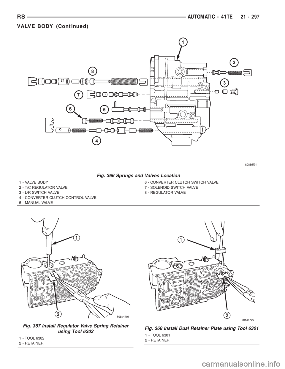
Fig. 366 Springs and Valves Location
1 - VALVE BODY
2 - T/C REGULATOR VALVE
3 - L/R SWITCH VALVE
4 - CONVERTER CLUTCH CONTROL VALVE
5 - MANUAL VALVE6 - CONVERTER CLUTCH SWITCH VALVE
7 - SOLENOID SWITCH VALVE
8 - REGULATOR VALVE
Fig. 367 Install Regulator Valve Spring Retainer
using Tool 6302
1 - TOOL 6302
2 - RETAINER
Fig. 368 Install Dual Retainer Plate using Tool 6301
1 - TOOL 6301
2 - RETAINER
RSAUTOMATIC - 41TE21 - 297
VALVE BODY (Continued)
Page 3263 of 4284
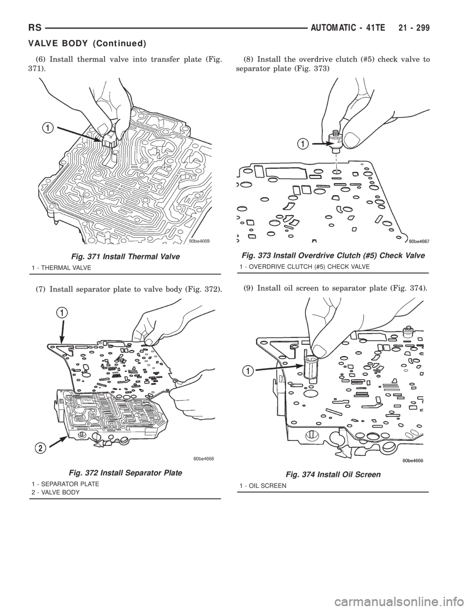
(6) Install thermal valve into transfer plate (Fig.
371).
(7) Install separator plate to valve body (Fig. 372).(8) Install the overdrive clutch (#5) check valve to
separator plate (Fig. 373)
(9) Install oil screen to separator plate (Fig. 374).
Fig. 371 Install Thermal Valve
1 - THERMAL VALVE
Fig. 372 Install Separator Plate
1 - SEPARATOR PLATE
2 - VALVE BODY
Fig. 373 Install Overdrive Clutch (#5) Check Valve
1 - OVERDRIVE CLUTCH (#5) CHECK VALVE
Fig. 374 Install Oil Screen
1 - OIL SCREEN
RSAUTOMATIC - 41TE21 - 299
VALVE BODY (Continued)
Page 3270 of 4284
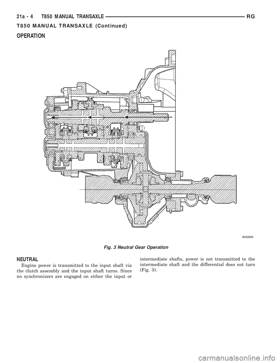
OPERATION
NEUTRAL
Engine power is transmitted to the input shaft via
the clutch assembly and the input shaft turns. Since
no synchronizers are engaged on either the input orintermediate shafts, power is not transmitted to the
intermediate shaft and the differential does not turn
(Fig. 3).
Fig. 3 Neutral Gear Operation
21a - 4 T850 MANUAL TRANSAXLERG
T850 MANUAL TRANSAXLE (Continued)