brake CHRYSLER VOYAGER 2001 Service Manual
[x] Cancel search | Manufacturer: CHRYSLER, Model Year: 2001, Model line: VOYAGER, Model: CHRYSLER VOYAGER 2001Pages: 4284, PDF Size: 83.53 MB
Page 3127 of 4284

TEST FIVE-SELECTOR IN OVERDRIVE (4th Gear-CC
on)
(1) Attach gauge to the torque converter clutch off
pressure tap.
(2) Move selector lever to the (OD) position.
(3) Allow vehicle wheels to turn and increase
throttle opening to achieve an indicated vehicle speed
of 50 mph. Vehicle should be in 4th gear, CC on.
CAUTION: Both wheels must turn at the same
speed.
(4) Torque converter clutch off pressure should be
less than 5 psi.
(5) This test checks the torque converter clutch
hydraulic circuit.
TEST SIX-SELECTOR IN REVERSE
(1) Attach gauges to the reverse and LR clutch
tap.
(2) Move selector lever to the (R) position.
(3) Read reverse clutch pressure with output sta-
tionary (foot on brake) and throttle opened to achieve
1500 rpm.(4) Reverse and LR clutch pressure should read
165 to 235 psi.
(5) This test checks the reverse clutch hydraulic
circuit.
TEST RESULT INDICATIONS
(1) If proper line pressure is found in any one test,
the pump and pressure regulator are working prop-
erly.
(2) Low pressure in all positions indicates a defec-
tive pump, a clogged filter, or a stuck pressure regu-
lator valve.
(3) Clutch circuit leaks are indicated if pressures
do not fall within the specified pressure range.
(4) If the overdrive clutch pressure is greater than
5 psi in Step 4 of Test Three, a worn reaction shaft
seal ring or a defective solenoid assembly is indi-
cated.
(5) If the underdrive clutch pressure is greater
than 5 psi in Step 4 of Test Two A, a defective sole-
noid assembly or TCM is the cause.
PRESSURE CHECK SPECIFICATIONS
Gear Selector
PositionActual
GearPressure Taps
Underdrive
ClutchOverdrive
ClutchReverse
ClutchTorque
Converter
Clutch Off2/4 ClutchLow/
Reverse
Clutch
Park *
PARK 0-2 0-5 0-2 60-110 0-2 115-145
0 mph
REVERSE *
REVERSE 0-2 0-7 165-235 50-100 0-2 165-235
0 mph
NEUTRAL *
NEUTRAL 0-2 0-5 0-2 60-110 0-2 115-145
0 mph
L#
FIRST 110-145 0-5 0-2 60-110 0-2 115-145
20 mph
3#
SECOND 110-145 0-5 0-2 60-110 115-145 0-2
30 mph
3#
DIRECT 75-95 75-95 0-2 60-90 0-2 0-2
45 mph
OD #
OVER-
DRIVE0-2 75-95 0-2 60-90 75-95 0-2
30 mph
OD #OVER-
DRIVE
WITH
TCC0-2 75-95 0-2 0-5 75-95 0-2
50 mph
* Engine speed at 1500 rpm
# CAUTION: Both front wheels must be turning at the same speed.
RSAUTOMATIC - 41TE21 - 163
AUTOMATIC - 41TE (Continued)
Page 3210 of 4284
FLUID
STANDARD PROCEDURE - FLUID LEVEL AND
CONDITION CHECK
NOTE: Only transmission fluid of the type labeled
Mopar ATF+4 (Automatic Transmission Fluid±Type
9602) should be used in this transaxle.
FLUID LEVEL CHECK
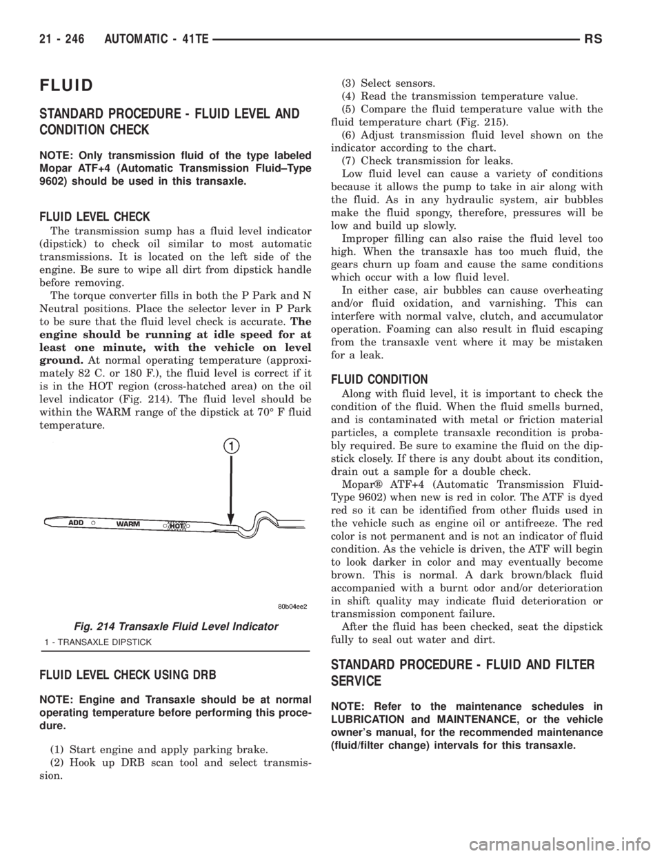
The transmission sump has a fluid level indicator
(dipstick) to check oil similar to most automatic
transmissions. It is located on the left side of the
engine. Be sure to wipe all dirt from dipstick handle
before removing.
The torque converter fills in both the P Park and N
Neutral positions. Place the selector lever in P Park
to be sure that the fluid level check is accurate.The
engine should be running at idle speed for at
least one minute, with the vehicle on level
ground.At normal operating temperature (approxi-
mately 82 C. or 180 F.), the fluid level is correct if it
is in the HOT region (cross-hatched area) on the oil
level indicator (Fig. 214). The fluid level should be
within the WARM range of the dipstick at 70É F fluid
temperature.
FLUID LEVEL CHECK USING DRB
NOTE: Engine and Transaxle should be at normal
operating temperature before performing this proce-
dure.
(1) Start engine and apply parking brake.
(2) Hook up DRB scan tool and select transmis-
sion.(3) Select sensors.
(4) Read the transmission temperature value.
(5) Compare the fluid temperature value with the
fluid temperature chart (Fig. 215).
(6) Adjust transmission fluid level shown on the
indicator according to the chart.
(7) Check transmission for leaks.
Low fluid level can cause a variety of conditions
because it allows the pump to take in air along with
the fluid. As in any hydraulic system, air bubbles
make the fluid spongy, therefore, pressures will be
low and build up slowly.
Improper filling can also raise the fluid level too
high. When the transaxle has too much fluid, the
gears churn up foam and cause the same conditions
which occur with a low fluid level.
In either case, air bubbles can cause overheating
and/or fluid oxidation, and varnishing. This can
interfere with normal valve, clutch, and accumulator
operation. Foaming can also result in fluid escaping
from the transaxle vent where it may be mistaken
for a leak.
FLUID CONDITION
Along with fluid level, it is important to check the
condition of the fluid. When the fluid smells burned,
and is contaminated with metal or friction material
particles, a complete transaxle recondition is proba-
bly required. Be sure to examine the fluid on the dip-
stick closely. If there is any doubt about its condition,
drain out a sample for a double check.
Moparž ATF+4 (Automatic Transmission Fluid-
Type 9602) when new is red in color. The ATF is dyed
red so it can be identified from other fluids used in
the vehicle such as engine oil or antifreeze. The red
color is not permanent and is not an indicator of fluid
condition. As the vehicle is driven, the ATF will begin
to look darker in color and may eventually become
brown. This is normal. A dark brown/black fluid
accompanied with a burnt odor and/or deterioration
in shift quality may indicate fluid deterioration or
transmission component failure.
After the fluid has been checked, seat the dipstick
fully to seal out water and dirt.
STANDARD PROCEDURE - FLUID AND FILTER
SERVICE
NOTE: Refer to the maintenance schedules in
LUBRICATION and MAINTENANCE, or the vehicle
owner's manual, for the recommended maintenance
(fluid/filter change) intervals for this transaxle.
Fig. 214 Transaxle Fluid Level Indicator
1 - TRANSAXLE DIPSTICK
21 - 246 AUTOMATIC - 41TERS
Page 3212 of 4284

(5) Pour four quarts of Moparž ATF+4 (Automatic
Transmission Fluid) Type 9602 through the dipstick
opening.
(6) Start engine and allow to idle for at least one
minute. Then, with parking and service brakes
applied, move selector lever momentarily to each
position, ending in the park or neutral position.
(7) Check the transaxle fluid level and add an
appropriate amount to bring the transaxle fluid level
to 3mm (1/8 in.) below the lowest mark on the dip-
stick (Fig. 217).
(8) Recheck the fluid level after the transaxle has
reached normal operating temperature (180ÉF.). Refer
to Fluid Level and Condition Check for the proper
fluid fill procedure.
(9) To prevent dirt from entering transaxle, make
certain that dipstick is fully seated into the dipstick
opening.
DIPSTICK TUBE FLUID SUCTION METHOD
(ALTERNATIVE)
(1) When performing the fluid suction method,
make sure the transaxle is at full operating temper-
ature.
(2) To perform the dipstick tube fluid suction
method, use a suitable fluid suction device (VaculaŸ
or equivalent).
(3) Insert the fluid suction line into the dipstick
tube.
NOTE: Verify that the suction line is inserted to the
lowest point of the transaxle oil pan. This will
ensure complete evacuation of the fluid in the pan.
(4) Follow the manufacturers recommended proce-
dure and evacuate the fluid from the transaxle.
(5) Remove the suction line from the dipstick tube.
(6) Pour four quarts of Moparž ATF+4 (Automatic
Transmission Fluid) Type 9602 through the dipstick
opening.(7) Start engine and allow to idle for at least one
minute. Then, with parking and service brakes
applied, move selector lever momentarily to each
position, ending in the park or neutral position.
(8) Check the transaxle fluid level and add an
appropriate amount to bring the transaxle fluid level
to 3mm (1/8 in.) below the lowest mark on the dip-
stick (Fig. 217).
(9) Recheck the fluid level after the transaxle has
reached normal operating temperature (180ÉF.).
(Refer to 21 - TRANSMISSION/TRANSAXLE/AUTO-
MATIC - 41TE/FLUID - STANDARD PROCEDURE)
(10) To prevent dirt from entering transaxle, make
certain that dipstick is fully seated into the dipstick
opening.
GEAR SHIFT CABLE
REMOVAL
(1) Disconnect battery cables.
(2) Remove battery shield.
(3) Remove battery.
(4) Remove speed control servo and position out of
way.
(5) Disconnect gear shift cable at manual valve
lever (Fig. 218).
(6) Disconnect gear shift cable from upper mount
bracket (Fig. 218).
Fig. 217 Transaxle Fluid Level Indicator
1 - TRANSAXLE DIPSTICK
Fig. 218 Gearshift Cable at Transaxle - Typical
1 - MANUAL VALVE LEVER
2 - GEAR SHIFT CABLE
3 - UPPER MOUNT BRACKET
21 - 248 AUTOMATIC - 41TERS
FLUID (Continued)
Page 3215 of 4284
GEARSHIFT CABLE ADJUSTMENT
VERIFICATION
(1) Place gearshift lever in gated park (P).
(2) Attempt to move vehicle by rocking back and
forth on level ground. If vehicle does not move,
attempt to start engine. If engine starts, the park
position is correct.
(3) Set parking brake.
(4) Turn key to on/run and depress brake pedal.
Place gearshift lever in neutral (N).
(5) Attempt to start engine. If engine starts in
both neutral (N) or park (P), gearshift cable is
adjusted properly. No adjustment is required.
(6) If engine does not start in either park (P) or
neutral (N), perform adjustment procedure.
ADJUSTMENT
(1) Park the vehicle on level ground and set the
parking brake.
(2) Place the gearshift lever in gated park (P) and
remove ignition key.
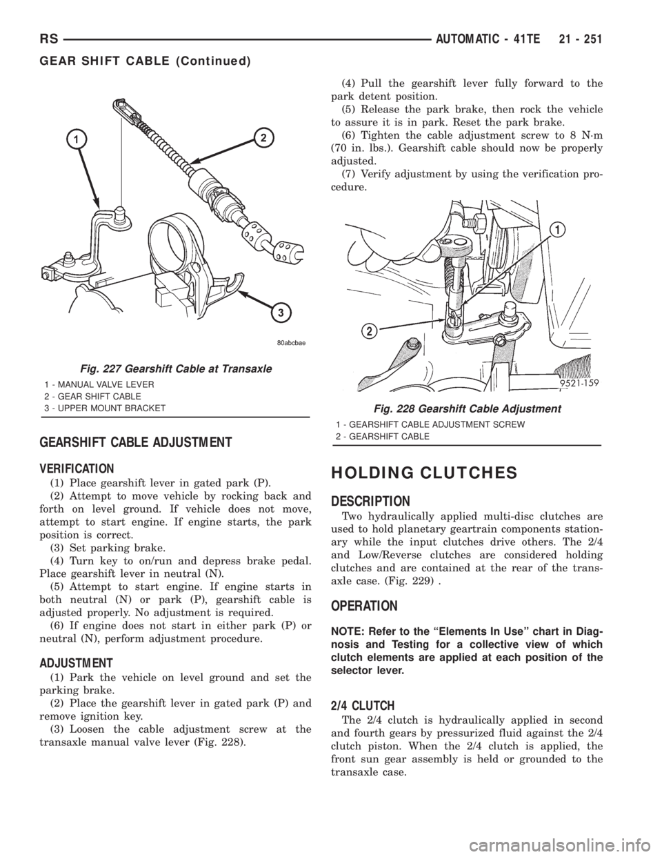
(3) Loosen the cable adjustment screw at the
transaxle manual valve lever (Fig. 228).(4) Pull the gearshift lever fully forward to the
park detent position.
(5) Release the park brake, then rock the vehicle
to assure it is in park. Reset the park brake.
(6) Tighten the cable adjustment screw to 8 N´m
(70 in. lbs.). Gearshift cable should now be properly
adjusted.
(7) Verify adjustment by using the verification pro-
cedure.
HOLDING CLUTCHES
DESCRIPTION
Two hydraulically applied multi-disc clutches are
used to hold planetary geartrain components station-
ary while the input clutches drive others. The 2/4
and Low/Reverse clutches are considered holding
clutches and are contained at the rear of the trans-
axle case. (Fig. 229) .
OPERATION
NOTE: Refer to the ªElements In Useº chart in Diag-
nosis and Testing for a collective view of which
clutch elements are applied at each position of the
selector lever.
2/4 CLUTCH
The 2/4 clutch is hydraulically applied in second
and fourth gears by pressurized fluid against the 2/4
clutch piston. When the 2/4 clutch is applied, the
front sun gear assembly is held or grounded to the
transaxle case.
Fig. 227 Gearshift Cable at Transaxle
1 - MANUAL VALVE LEVER
2 - GEAR SHIFT CABLE
3 - UPPER MOUNT BRACKET
Fig. 228 Gearshift Cable Adjustment
1 - GEARSHIFT CABLE ADJUSTMENT SCREW
2 - GEARSHIFT CABLE
RSAUTOMATIC - 41TE21 - 251
GEAR SHIFT CABLE (Continued)
Page 3236 of 4284
INSTALLATION
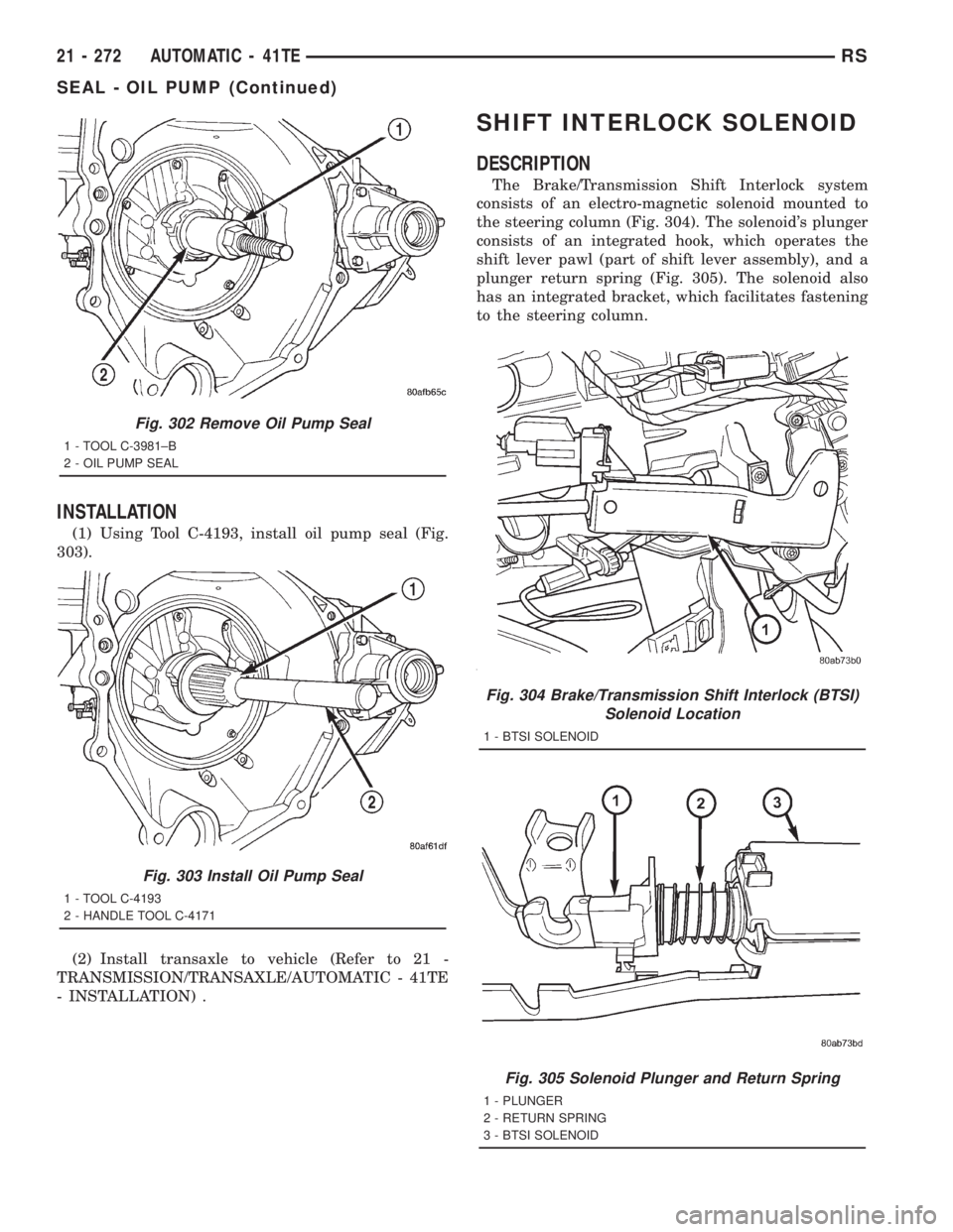
(1) Using Tool C-4193, install oil pump seal (Fig.
303).
(2) Install transaxle to vehicle (Refer to 21 -
TRANSMISSION/TRANSAXLE/AUTOMATIC - 41TE
- INSTALLATION) .
SHIFT INTERLOCK SOLENOID
DESCRIPTION
The Brake/Transmission Shift Interlock system
consists of an electro-magnetic solenoid mounted to
the steering column (Fig. 304). The solenoid's plunger
consists of an integrated hook, which operates the
shift lever pawl (part of shift lever assembly), and a
plunger return spring (Fig. 305). The solenoid also
has an integrated bracket, which facilitates fastening
to the steering column.
Fig. 302 Remove Oil Pump Seal
1 - TOOL C-3981±B
2 - OIL PUMP SEAL
Fig. 303 Install Oil Pump Seal
1 - TOOL C-4193
2 - HANDLE TOOL C-4171
Fig. 304 Brake/Transmission Shift Interlock (BTSI)
Solenoid Location
1 - BTSI SOLENOID
Fig. 305 Solenoid Plunger and Return Spring
1 - PLUNGER
2 - RETURN SPRING
3 - BTSI SOLENOID
21 - 272 AUTOMATIC - 41TERS
SEAL - OIL PUMP (Continued)
Page 3237 of 4284
OPERATION
The Brake/Transmission Shift Interlock (BTSI)
Solenoid prevents the transmission shift lever from
being moved out of PARK (P) unless the brake pedal
is applied. The BTSI solenoid is hardwired to and
controlled by the Intelligent Power Module (IPM).
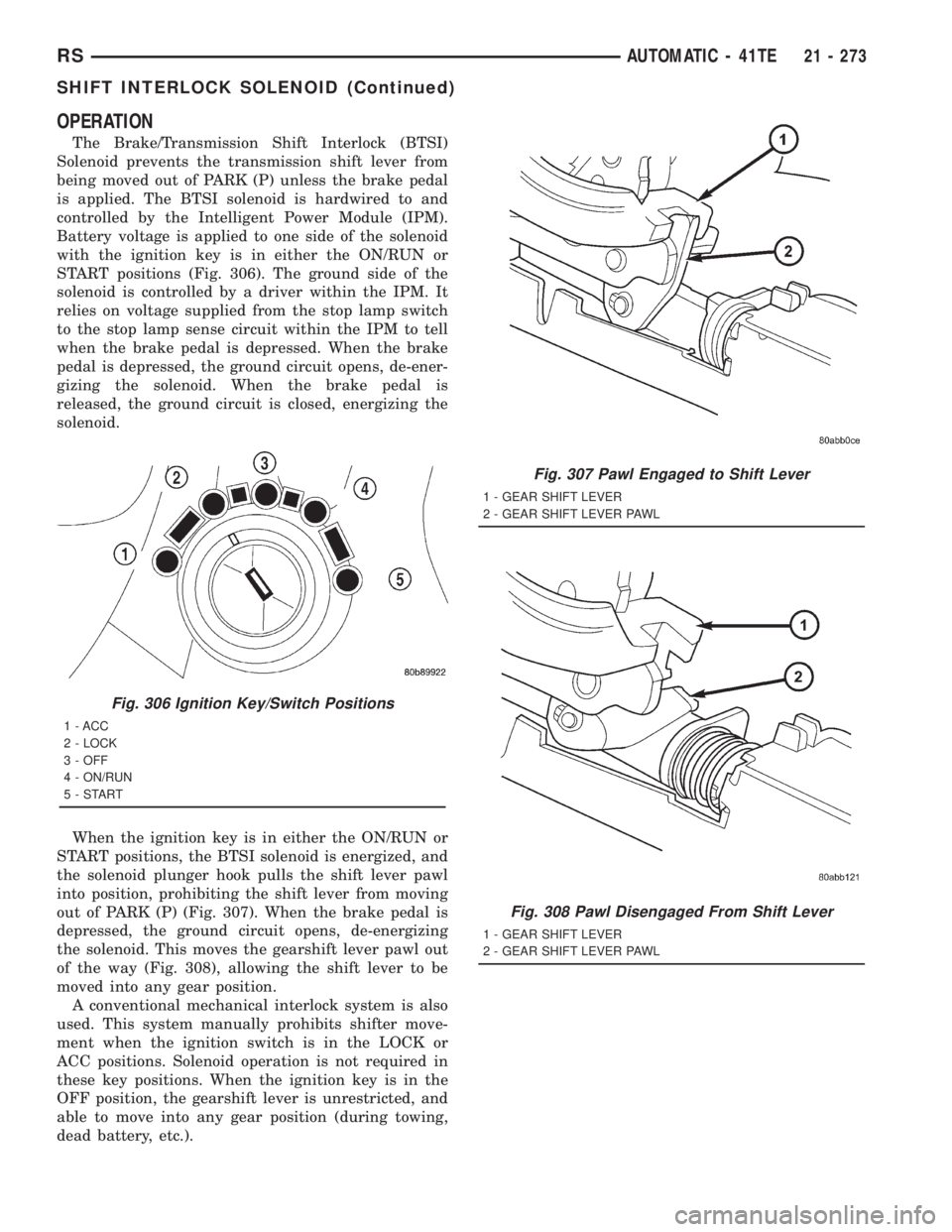
Battery voltage is applied to one side of the solenoid
with the ignition key is in either the ON/RUN or
START positions (Fig. 306). The ground side of the
solenoid is controlled by a driver within the IPM. It
relies on voltage supplied from the stop lamp switch
to the stop lamp sense circuit within the IPM to tell
when the brake pedal is depressed. When the brake
pedal is depressed, the ground circuit opens, de-ener-
gizing the solenoid. When the brake pedal is
released, the ground circuit is closed, energizing the
solenoid.
When the ignition key is in either the ON/RUN or
START positions, the BTSI solenoid is energized, and
the solenoid plunger hook pulls the shift lever pawl
into position, prohibiting the shift lever from moving
out of PARK (P) (Fig. 307). When the brake pedal is
depressed, the ground circuit opens, de-energizing
the solenoid. This moves the gearshift lever pawl out
of the way (Fig. 308), allowing the shift lever to be
moved into any gear position.
A conventional mechanical interlock system is also
used. This system manually prohibits shifter move-
ment when the ignition switch is in the LOCK or
ACC positions. Solenoid operation is not required in
these key positions. When the ignition key is in the
OFF position, the gearshift lever is unrestricted, and
able to move into any gear position (during towing,
dead battery, etc.).
Fig. 306 Ignition Key/Switch Positions
1 - ACC
2 - LOCK
3 - OFF
4 - ON/RUN
5-START
Fig. 307 Pawl Engaged to Shift Lever
1 - GEAR SHIFT LEVER
2 - GEAR SHIFT LEVER PAWL
Fig. 308 Pawl Disengaged From Shift Lever
1 - GEAR SHIFT LEVER
2 - GEAR SHIFT LEVER PAWL
RSAUTOMATIC - 41TE21 - 273
SHIFT INTERLOCK SOLENOID (Continued)
Page 3238 of 4284
For intended BTSI system operation, refer to the
following chart:
ACTION EXPECTED RESPONSE
1. Turn key to the9OFF9
position.1. Shifter CAN be shifted
out of park.
2. Turn key to the
9ON/RUN9position.2. Shifter CANNOT be
shifted out of park.
3. Turn key to the
9ON/RUN9position and
depress the brake pedal.3. Shifter CAN be shifted
out of park.
4. Leave shifter in any
gear and try to return key
to the9LOCK9or9ACC9
position.4. Key cannot be
returned to the9LOCK9or
9ACC9position.
5. Return shifter to
9PARK9and try to remove
the key.5. Key can be removed
(after returning to9LOCK9
position).
6. With the key removed,
try to shift out of9PARK9.6. Shifter cannot be
shifted out of9PARK9.
NOTE: Any failure to meet these expected
responses requires system adjustment or repair.
DIAGNOSIS AND TESTING - BRAKE/
TRANSMISSION SHIFT INTERLOCK SOLENOID
For intended BTSI system operation, refer to the
following chart:
ACTION EXPECTED RESPONSE
1. Turn key to the9OFF9
position.1. Shifter CAN be shifted
out of park.
2. Turn key to the
9ON/RUN9position.2. Shifter CANNOT be
shifted out of park.
3. Turn key to the
9ON/RUN9position and
depress the brake pedal.3. Shifter CAN be shifted
out of park.
4. Leave shifter in any
gear and try to return key
to the9LOCK9or9ACC9
position.4. Key cannot be
returned to the9LOCK9or
9ACC9position.
5. Return shifter to
9PARK9and try to remove
the key.5. Key can be removed
(after returning to9LOCK9
position).
6. With the key removed,
try to shift out of9PARK9.6. Shifter cannot be
shifted out of9PARK9.
NOTE: Any failure to meet these expected
responses requires system repair. Refer to the
appropriate Diagnostic Information.
REMOVAL
(1) Disconnect battery negative cable.
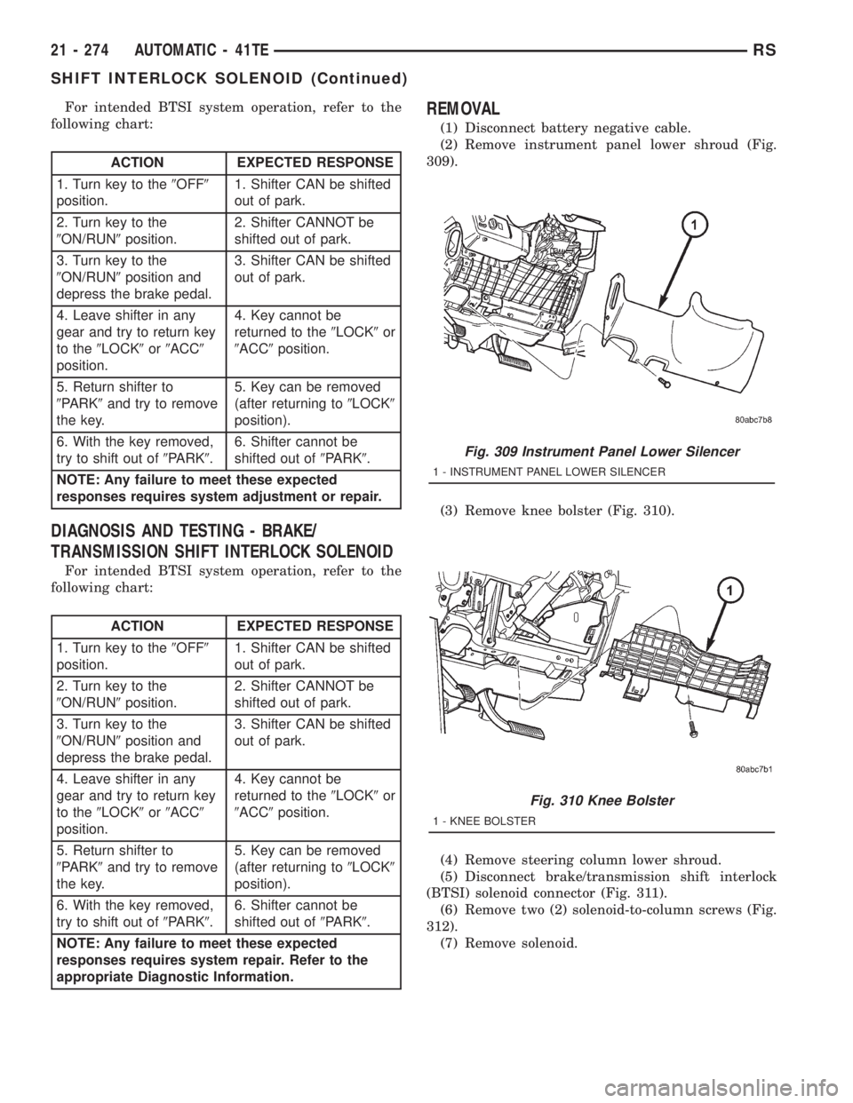
(2) Remove instrument panel lower shroud (Fig.
309).
(3) Remove knee bolster (Fig. 310).
(4) Remove steering column lower shroud.
(5) Disconnect brake/transmission shift interlock
(BTSI) solenoid connector (Fig. 311).
(6) Remove two (2) solenoid-to-column screws (Fig.
312).
(7) Remove solenoid.
Fig. 309 Instrument Panel Lower Silencer
1 - INSTRUMENT PANEL LOWER SILENCER
Fig. 310 Knee Bolster
1 - KNEE BOLSTER
21 - 274 AUTOMATIC - 41TERS
SHIFT INTERLOCK SOLENOID (Continued)
Page 3320 of 4284

GEARSHIFT CABLE -
CROSSOVER
REMOVAL
(1) Disconnect battery negative cable.
(2) Remove gearshift knob by pushing down and
rotating ò-turn clock-wise (Fig. 139).(3) Remove gearshift boot from center console by
disengaging at three (3) retaining clips (Fig. 140).
(4) Apply park brake to allow park brake handle to
clear center console upon removal.
(5) Remove two (2) cupholder bottom plugs (Fig.
141).
(6) Remove four (4) center console-to-gearshift
mechanism screws. Remove console assembly (Fig.
142).
Fig. 138 Gearshift Boot Removal/Installation
1 - GEARSHIFT BOOT
2 - CENTER CONSOLE
Fig. 139 Gearshift Knob Removal/Installation
1 - GEARSHIFT KNOB
2 - GEARSHIFT LEVER
Fig. 140 Gearshift Boot Removal/Installation
1 - GEARSHIFT BOOT
2 - CENTER CONSOLE
Fig. 141 Cup Holder Plugs
1 - CUPHOLDER PLUG (2)
21a - 54 T850 MANUAL TRANSAXLERG
GEARSHIFT BOOT (Continued)
Page 3326 of 4284

ADJUSTMENT
(1) Disconnect battery negative cable.
(2) Remove gearshift knob by pushing down and
rotating ò-turn clock-wise (Fig. 163).(3) Remove gearshift boot from center console by
disengaging at three (3) retaining clips (Fig. 164).
(4) Apply park brake to allow park brake handle to
clear center console upon removal.
(5) Remove two (2) cupholder bottom plugs (Fig.
165).
Fig. 162 Gearshift Knob Removal/Installation
1 - GEARSHIFT KNOB
2 - GEARSHIFT LEVER
Fig. 163 Gearshift Knob Removal/Installation
1 - GEARSHIFT KNOB
2 - GEARSHIFT LEVER
Fig. 164 Gearshift Boot Removal/Installation
1 - GEARSHIFT BOOT
2 - CENTER CONSOLE
Fig. 165 Cup Holder Plugs
1 - CUPHOLDER PLUG (2)
21a - 60 T850 MANUAL TRANSAXLERG
GEARSHIFT CABLE - CROSSOVER (Continued)
Page 3328 of 4284
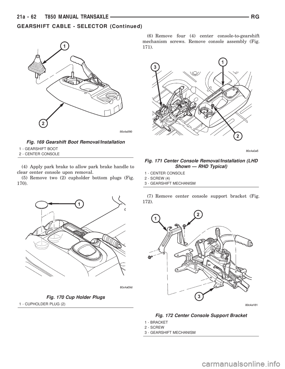
(4) Apply park brake to allow park brake handle to
clear center console upon removal.
(5) Remove two (2) cupholder bottom plugs (Fig.
170).(6) Remove four (4) center console-to-gearshift
mechanism screws. Remove console assembly (Fig.
171).
(7) Remove center console support bracket (Fig.
172).
Fig. 169 Gearshift Boot Removal/Installation
1 - GEARSHIFT BOOT
2 - CENTER CONSOLE
Fig. 170 Cup Holder Plugs
1 - CUPHOLDER PLUG (2)
Fig. 171 Center Console Removal/Installation (LHD
Shown Ð RHD Typical)
1 - CENTER CONSOLE
2 - SCREW (4)
3 - GEARSHIFT MECHANISM
Fig. 172 Center Console Support Bracket
1 - BRACKET
2 - SCREW
3 - GEARSHIFT MECHANISM
21a - 62 T850 MANUAL TRANSAXLERG
GEARSHIFT CABLE - SELECTOR (Continued)