brake CHRYSLER VOYAGER 2001 Service Manual
[x] Cancel search | Manufacturer: CHRYSLER, Model Year: 2001, Model line: VOYAGER, Model: CHRYSLER VOYAGER 2001Pages: 4284, PDF Size: 83.53 MB
Page 2936 of 4284

WARNING: SAFETY GOGGLES SHOULD BE WORN
AT ALL TIMES WHEN WORKING ON STEERING
COLUMNS.
CAUTION: Disconnect negative (ground) cable from
the battery before servicing any column compo-
nent.
CAUTION: Do not attempt to remove the pivot pins
to disassemble the tilting mechanism. Damage will
occur.
DIAGNOSIS AND TESTING
For diagnosis of conditions relating to the steering
column (Refer to 19 - STEERING - DIAGNOSIS AND
TESTING) and (Refer to 19 - STEERING - DIAGNO-
SIS AND TESTING).
REMOVAL
To service the steering wheel components or the
airbag (Refer to 8 - ELECTRICAL/RESTRAINTS/
DRIVER AIRBAG - REMOVAL). Follow all WARN-
INGS AND CAUTIONS.
(1) Make sure the front wheels of the vehicle are
in the STRAIGHT AHEAD position before beginning
the column removal procedure.
(2) Disconnect negative (ground) cable from the
battery and isolate cable from battery terminal.
(3) Remove the lower shroud (Refer to 19 -
STEERING/COLUMN/LOWER SHROUD - REMOV-
AL).
(4) Remove the traction off switch.
(5) Remove the upper shroud.
(6) Remove the cluster trim bezel (Refer to 23 -
BODY/INSTRUMENT PANEL/CLUSTER BEZEL -
REMOVAL).(7) Remove the knee blocker (Refer to 23 - BODY/
INSTRUMENT PANEL/STEERING COLUMN
OPENING COVER - REMOVAL).
(8) Remove the parking brake handle link.
(9) Remove the knee blocker reinforcement (Refer
to 23 - BODY/INSTRUMENT PANEL/KNEE
BLOCKER - REMOVAL).
(10) Remove the airbag (Refer to 8 - ELECTRI-
CAL/RESTRAINTS/DRIVER AIRBAG - REMOVAL).
(11) Remove the steering wheel retaining nut.
(12) Remove the vibration damper weight.
(13) Remove the steering wheel (Refer to 19 -
STEERING/COLUMN/STEERING WHEEL -
REMOVAL). (Fig. 3)
(14) Disconnect the wiring harness connectors
from the clockspring, multi-function switch, halo
lamp, SKIM module, ignition switch and BTSI sole-
noid.
(15) Disconnect the shift cable at the lever. (Fig. 4)
1 - CLOCKSPRING WIRING
2 - STEERING WHEEL
3 - UPPER SHROUD
4 - FIXED SHROUD
5 - SCREW
6 - STEERING COLUMN MOUNTING PLATE
7 - NUT
8 - DASH PANEL STEERING COLUMN MOUNTING BRACKET
9 - STUDS 4
10 - STEERING COLUMN LOCKING PIN
11 - NUT/WASHER ASSEMBLY
12 - STEERING COLUMN ASSEMBLY
13 - LOWER SHROUD
14 - SCREWS
15 - STEERING WHEEL RETAINING NUT16 - STEERING WHEEL DAMPER
17 - CLOCKSPRING
18 - SCREW
19 - MULTI-FUNCTION SWITCH MOUNTING/HOUSING
20 - PINCH BOLT
21 - STEERING COLUMN COUPLER
22 - PINCH BOLT RETAINING PIN
23 - DASH PANEL
24 - SILENCER SHELL
25 - INTERMEDIATE SHAFT SHIELD AND SEAL
26 - INTERMEDIATE SHAFT
27 - ROLL PIN
28 - STEERING GEAR
29 - FRONT SUSPENSION CRADLE
Fig. 3 STEERING WHEEL REMOVAL
1 - STEERING WHEEL
2 - PULLER
19 - 12 COLUMNRS
COLUMN (Continued)
Page 2938 of 4284
(16) Install the steering wheel retaining nut.
Tighten the nut to 61 N´m (45 ft. lbs.)
(17) Install the airbag (Refer to 8 - ELECTRICAL/
RESTRAINTS/DRIVER AIRBAG - INSTALLATION).
(18) Install the knee blocker reinforcement (Refer
to 23 - BODY/INSTRUMENT PANEL/KNEE
BLOCKER - INSTALLATION).
(19) Install the parking brake handle link.
(20) Install the knee blocker (Refer to 23 - BODY/
INSTRUMENT PANEL/STEERING COLUMN
OPENING COVER - INSTALLATION).
(21) Install the cluster trim bezel (Refer to 23 -
BODY/INSTRUMENT PANEL/CLUSTER BEZEL -
INSTALLATION).
(22) Install the upper shroud (Refer to 19 -
STEERING/COLUMN/LOWER SHROUD - INSTAL-
LATION).
(23) Install the traction off switch.
(24) Install the lower shroud.
SPECIFICATIONS
COLUMN TORQUE
DESCRIPTION N´mFt.
Lbs.In.
Lbs.
Steering Wheel Retaining
Nut61 45 Ð
Steering Column Mounting
Bracket Attaching Nuts12 Ð 105
Steering Column Coupling
Pinch Bolt28 Ð 250
Steering Column Airbag
Module Attaching Nuts11 Ð 100
KEY/LOCK CYLINDER
DESCRIPTION
The lock cylinder is inserted in the end of the
housing opposite the ignition switch.
OPERATION
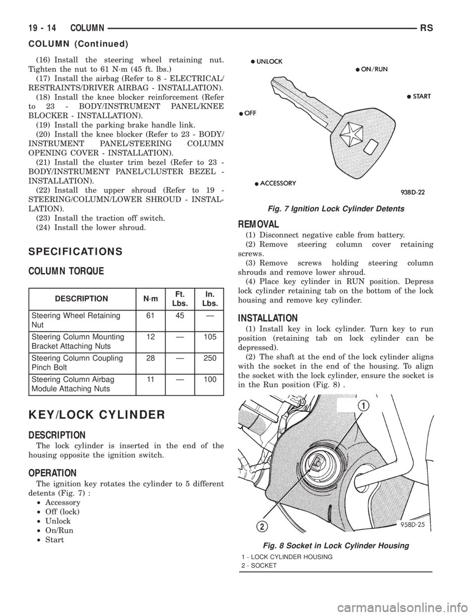
The ignition key rotates the cylinder to 5 different
detents (Fig. 7) :
²Accessory
²Off (lock)
²Unlock
²On/Run
²Start
REMOVAL
(1) Disconnect negative cable from battery.
(2) Remove steering column cover retaining
screws.
(3) Remove screws holding steering column
shrouds and remove lower shroud.
(4) Place key cylinder in RUN position. Depress
lock cylinder retaining tab on the bottom of the lock
housing and remove key cylinder.
INSTALLATION
(1) Install key in lock cylinder. Turn key to run
position (retaining tab on lock cylinder can be
depressed).
(2) The shaft at the end of the lock cylinder aligns
with the socket in the end of the housing. To align
the socket with the lock cylinder, ensure the socket is
in the Run position (Fig. 8) .
Fig. 7 Ignition Lock Cylinder Detents
Fig. 8 Socket in Lock Cylinder Housing
1 - LOCK CYLINDER HOUSING
2 - SOCKET
19 - 14 COLUMNRS
COLUMN (Continued)
Page 2985 of 4284
AUTOMATIC - 31TH
TABLE OF CONTENTS
page page
AUTOMATIC - 31TH
DESCRIPTION...........................22
OPERATION.............................24
DIAGNOSIS AND TESTING.................24
PRELIMINARY DIAGNOSIS...............24
ROAD TEST...........................31
HYDRAULIC PRESSURE TESTS...........32
TORQUE CONVERTER HOUSING FLUID
LEAKAGE.............................34
CLUTCH AND SERVO AIR PRESSURE
TESTS...............................35
STANDARD PROCEDURE..................36
ALUMINUM THREAD REPAIR.............36
REMOVAL..............................36
DISASSEMBLY...........................39
ASSEMBLY.............................50
INSTALLATION...........................59
SCHEMATICS AND DIAGRAMS..............63
SPECIFICATIONS........................71
SPECIAL TOOLS.........................74
ACCUMULATOR
DESCRIPTION...........................78
OPERATION.............................78
BANDS
DESCRIPTION...........................79
OPERATION.............................79
ADJUSTMENTS..........................79
CLUTCH - FRONT
DESCRIPTION...........................80
OPERATION.............................81
DISASSEMBLY...........................81
ASSEMBLY.............................84
CLUTCH - REAR
DESCRIPTION...........................85
OPERATION.............................85
DISASSEMBLY...........................86
ASSEMBLY.............................89
FINAL DRIVE
DISASSEMBLY...........................90
ASSEMBLY.............................94
ADJUSTMENTS..........................96
FLUID
STANDARD PROCEDURE..................98
FLUID LEVEL AND CONDITION CHECK......98
FLUID AND FILTER CHANGE..............98
GEAR SHIFT CABLE
REMOVAL.............................100
INSTALLATION..........................101
ADJUSTMENTS.........................103GOVERNOR
DESCRIPTION..........................103
OPERATION............................103
CLEANING.............................104
INSPECTION...........................104
OIL PUMP
DESCRIPTION..........................104
OPERATION............................104
STANDARD PROCEDURE.................105
OIL PUMP VOLUME CHECK..............105
DISASSEMBLY..........................105
CLEANING.............................105
INSPECTION...........................105
ASSEMBLY............................105
PARK/NEUTRAL POSITION SWITCH
DIAGNOSIS AND TESTING................106
PARK/NEUTRAL POSITION SWITCH.......106
REMOVAL.............................106
INSTALLATION..........................107
PLANETARY GEARTRAIN
DISASSEMBLY..........................107
ASSEMBLY............................107
SEAL - OIL PUMP
REMOVAL.............................109
INSTALLATION..........................109
SERVO - KICKDOWN
DESCRIPTION..........................109
OPERATION............................109
DISASSEMBLY..........................110
CLEANING.............................111
INSPECTION...........................111
ASSEMBLY.............................112
SERVO - LOW/REVERSE
DESCRIPTION..........................112
OPERATION............................112
DISASSEMBLY..........................112
CLEANING.............................113
ASSEMBLY.............................113
SHIFT INTERLOCK SOLENOID
DESCRIPTION..........................113
OPERATION............................114
DIAGNOSIS AND TESTING................115
BRAKE/TRANSMISSION SHIFT INTERLOCK
SOLENOID...........................115
REMOVAL.............................115
INSTALLATION..........................116
SOLENOID - TCC
DESCRIPTION..........................117
OPERATION............................117
RSAUTOMATIC - 31TH21-21
Page 3063 of 4284
(2) Loosen pan bolts and tap the pan at one corner
to break it loose allowing fluid to drain, then remove
the oil pan.
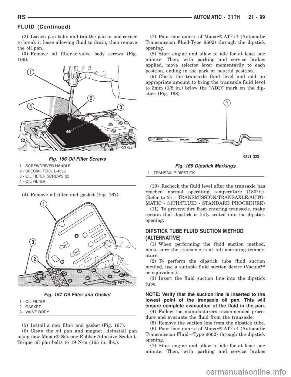
(3) Remove oil filter-to-valve body screws (Fig.
166).
(4) Remove oil filter and gasket (Fig. 167).
(5) Install a new filter and gasket (Fig. 167).
(6) Clean the oil pan and magnet. Reinstall pan
using new Moparž Silicone Rubber Adhesive Sealant.
Torque oil pan bolts to 19 N´m (165 in. lbs.).(7) Pour four quarts of Moparž ATF+4 (Automatic
Transmission Fluid-Type 9602) through the dipstick
opening.
(8) Start engine and allow to idle for at least one
minute. Then, with parking and service brakes
applied, move selector lever momentarily to each
position, ending in the park or neutral position.
(9) Check the transaxle fluid level and add an
appropriate amount to bring the transaxle fluid level
to 3mm (1/8 in.) below the ªADDº mark on the dip-
stick (Fig. 168).
(10) Recheck the fluid level after the transaxle has
reached normal operating temperature (180ÉF.).
(Refer to 21 - TRANSMISSION/TRANSAXLE/AUTO-
MATIC - 31TH/FLUID - STANDARD PROCEDURE)
(11) To prevent dirt from entering transaxle, make
certain that dipstick is fully seated into the dipstick
opening.
DIPSTICK TUBE FLUID SUCTION METHOD
(ALTERNATIVE)
(1) When performing the fluid suction method,
make sure the transaxle is at full operating temper-
ature.
(2) To perform the dipstick tube fluid suction
method, use a suitable fluid suction device (VaculaŸ
or equivalent).
(3) Insert the fluid suction line into the dipstick
tube.
NOTE: Verify that the suction line is inserted to the
lowest point of the transaxle oil pan. This will
ensure complete evacuation of the fluid in the pan.
(4) Follow the manufacturers recommended proce-
dure and evacuate the fluid from the transaxle.
(5) Remove the suction line from the dipstick tube.
(6) Pour four quarts of Moparž ATF+4 (Automatic
Transmission FluidÐType 9602) through the dipstick
opening.
(7) Start engine and allow to idle for at least one
minute. Then, with parking and service brakes
Fig. 166 Oil Filter Screws
1 - SCREWDRIVER HANDLE
2 - SPECIAL TOOL L-4553
3 - OIL FILTER SCREWS (2)
4 - OIL FILTER
Fig. 167 Oil Filter and Gasket
1 - OIL FILTER
2 - GASKET
3 - VALVE BODY
Fig. 168 Dipstick Markings
1 - TRANSAXLE DIPSTICK
RSAUTOMATIC - 31TH21-99
FLUID (Continued)
Page 3067 of 4284
GEARSHIFT CABLE ADJUSTMENT
Lift and rotate the gearshift hand lever into the
park (P) gate position and remove the ignition key.
This confirms the shift lever is in the gated park (P)
position.
After confirming the park gate position, turn the
ignition switch . If the starter will operate, the park
gate position is correct. Move the shift lever into the
neutral (N) position. If the starter will operate in this
position, the linkage is properly adjusted. If the
starter fails to operate in either position, linkage
adjustment is required.
(1) Park the vehicle on level ground and set the
parking brake.
(2) Place the gearshift lever in park (P) gate posi-
tion and remove key.
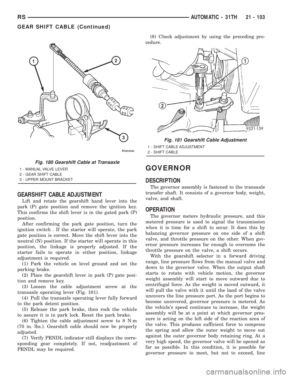
(3) Loosen the cable adjustment screw at the
transaxle operating lever (Fig. 181).
(4) Pull the transaxle operating lever fully forward
to the park detent position.
(5) Release the park brake, then rock the vehicle
to assure it is in park lock. Reset the park brake.
(6) Tighten the cable adjustment screw to 8 N´m
(70 in. lbs.). Gearshift cable should now be properly
adjusted.
(7) Verify PRNDL indicator still displays the corre-
sponding gear completely. If not, readjustment of
PRNDL may be required.(8) Check adjustment by using the preceding pro-
cedure.
GOVERNOR
DESCRIPTION
The governor assembly is fastened to the transaxle
transfer shaft. It consists of a governor body, weight,
valve, and shaft.
OPERATION
The governor meters hydraulic pressure, and this
metered pressure is used to signal the transmission
when it is time for a shift to occur. It does this by
balancing governor pressure on one side of a shift
valve, and throttle pressure on the other. When gov-
ernor pressure increases far enough to overcome the
throttle pressure on the valve, a shift occurs.
With the gearshift selector in a forward driving
range, line pressure flows from the manual valve and
down to the governor valve. When the output shaft
starts to rotate with vehicle motion, the governor
weight assembly will start to move outward due to
centrifugal force. As the weight is moved outward, it
will pull the valve with it until the land of the valve
uncovers the line pressure port. As the port begins to
become uncovered, governor pressure is metered. As
the vehicle's speed continues to increase, the weight
assembly will be at a point at which governor pres-
sure is acting on the left side of the reaction area of
the valve. This produces sufficient force to compress
the spring and allow the outer weight to move out
against the outer governor body retaining ring. At a
very high speed, the governor valve will be opened as
far as possible. In this condition, it is possible for
governor pressure to meet, but not to exceed, line
Fig. 180 Gearshift Cable at Transaxle
1 - MANUAL VALVE LEVER
2 - GEAR SHIFT CABLE
3 - UPPER MOUNT BRACKET
Fig. 181 Gearshift Cable Adjustment
1 - SHIFT CABLE ADJUSTMENT
2 - SHIFT CABLE
RSAUTOMATIC - 31TH21 - 103
GEAR SHIFT CABLE (Continued)
Page 3077 of 4284

(3) Remove retainer, spring and servo (Fig. 206).
CLEANING
Remove and discard the servo piston seal ring (Fig.
207). Then clean the servo components with solvent
and dry with compressed air. Replace either spring if
collapsed, distorted or broken. Replace the plug and
piston if cracked, bent, or worn. Discard the servo
snap-rings and use new ones at assembly.
ASSEMBLY
(1) Install low/reverse servo assembly (Fig. 208).
(2) Install low/reverse servo snap ring (Fig. 205).
SHIFT INTERLOCK SOLENOID
DESCRIPTION
The Brake/Transmission Shift Interlock system
consists of an electro-magnetic solenoid mounted to
the steering column (Fig. 209). The solenoid's plunger
consists of an integrated hook, which operates the
shift lever pawl (part of shift lever assembly), and a
plunger return spring (Fig. 210). The solenoid also
has an integrated bracket, which facilitates fastening
to the steering column.
Fig. 206 Remove Retainer, Spring and Servo
1 - SERVO PISTON
2 - SPRING AND RETAINER
Fig. 207 Rear Servo Components
1 - SNAP-RING
2 - PISTON SEAL
3 - PISTON PLUG
4 - SPRING RETAINER
5 - SNAP-RING
6 - PISTON SPRING
7 - CUSHION SPRING
8 - PISTON
Fig. 208 Low/Reverse Servo Assembly
1 - SERVO PISTON
2 - SPRING
Fig. 209 Brake/Transmission Shift Interlock (BTSI)
Solenoid Location
1 - BTSI SOLENOID
RSAUTOMATIC - 31TH21 - 113
SERVO - LOW/REVERSE (Continued)
Page 3078 of 4284
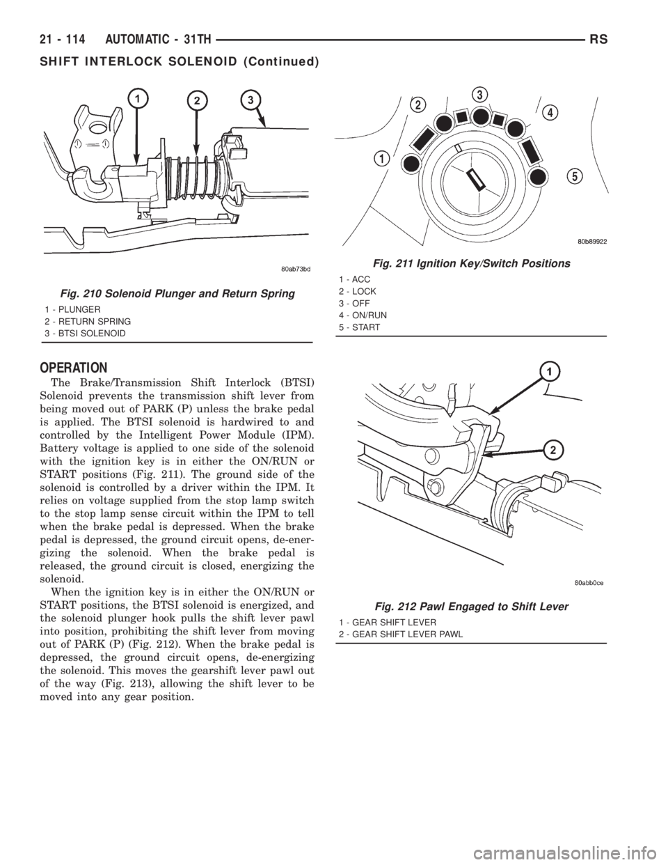
OPERATION
The Brake/Transmission Shift Interlock (BTSI)
Solenoid prevents the transmission shift lever from
being moved out of PARK (P) unless the brake pedal
is applied. The BTSI solenoid is hardwired to and
controlled by the Intelligent Power Module (IPM).
Battery voltage is applied to one side of the solenoid
with the ignition key is in either the ON/RUN or
START positions (Fig. 211). The ground side of the
solenoid is controlled by a driver within the IPM. It
relies on voltage supplied from the stop lamp switch
to the stop lamp sense circuit within the IPM to tell
when the brake pedal is depressed. When the brake
pedal is depressed, the ground circuit opens, de-ener-
gizing the solenoid. When the brake pedal is
released, the ground circuit is closed, energizing the
solenoid.
When the ignition key is in either the ON/RUN or
START positions, the BTSI solenoid is energized, and
the solenoid plunger hook pulls the shift lever pawl
into position, prohibiting the shift lever from moving
out of PARK (P) (Fig. 212). When the brake pedal is
depressed, the ground circuit opens, de-energizing
the solenoid. This moves the gearshift lever pawl out
of the way (Fig. 213), allowing the shift lever to be
moved into any gear position.
Fig. 210 Solenoid Plunger and Return Spring
1 - PLUNGER
2 - RETURN SPRING
3 - BTSI SOLENOID
Fig. 211 Ignition Key/Switch Positions
1 - ACC
2 - LOCK
3 - OFF
4 - ON/RUN
5-START
Fig. 212 Pawl Engaged to Shift Lever
1 - GEAR SHIFT LEVER
2 - GEAR SHIFT LEVER PAWL
21 - 114 AUTOMATIC - 31THRS
SHIFT INTERLOCK SOLENOID (Continued)
Page 3079 of 4284
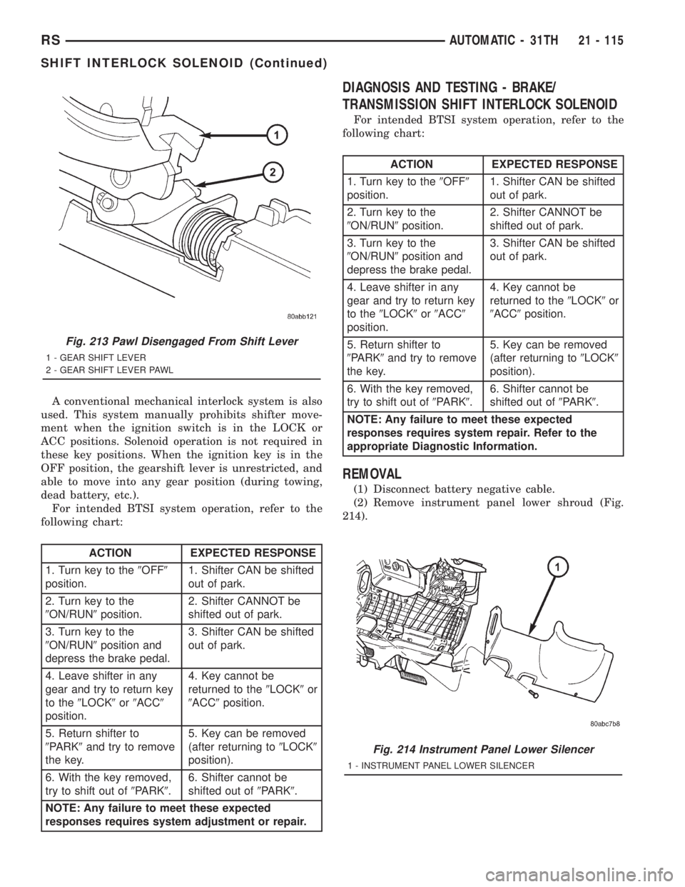
A conventional mechanical interlock system is also
used. This system manually prohibits shifter move-
ment when the ignition switch is in the LOCK or
ACC positions. Solenoid operation is not required in
these key positions. When the ignition key is in the
OFF position, the gearshift lever is unrestricted, and
able to move into any gear position (during towing,
dead battery, etc.).
For intended BTSI system operation, refer to the
following chart:
ACTION EXPECTED RESPONSE
1. Turn key to the9OFF9
position.1. Shifter CAN be shifted
out of park.
2. Turn key to the
9ON/RUN9position.2. Shifter CANNOT be
shifted out of park.
3. Turn key to the
9ON/RUN9position and
depress the brake pedal.3. Shifter CAN be shifted
out of park.
4. Leave shifter in any
gear and try to return key
to the9LOCK9or9ACC9
position.4. Key cannot be
returned to the9LOCK9or
9ACC9position.
5. Return shifter to
9PARK9and try to remove
the key.5. Key can be removed
(after returning to9LOCK9
position).
6. With the key removed,
try to shift out of9PARK9.6. Shifter cannot be
shifted out of9PARK9.
NOTE: Any failure to meet these expected
responses requires system adjustment or repair.
DIAGNOSIS AND TESTING - BRAKE/
TRANSMISSION SHIFT INTERLOCK SOLENOID
For intended BTSI system operation, refer to the
following chart:
ACTION EXPECTED RESPONSE
1. Turn key to the9OFF9
position.1. Shifter CAN be shifted
out of park.
2. Turn key to the
9ON/RUN9position.2. Shifter CANNOT be
shifted out of park.
3. Turn key to the
9ON/RUN9position and
depress the brake pedal.3. Shifter CAN be shifted
out of park.
4. Leave shifter in any
gear and try to return key
to the9LOCK9or9ACC9
position.4. Key cannot be
returned to the9LOCK9or
9ACC9position.
5. Return shifter to
9PARK9and try to remove
the key.5. Key can be removed
(after returning to9LOCK9
position).
6. With the key removed,
try to shift out of9PARK9.6. Shifter cannot be
shifted out of9PARK9.
NOTE: Any failure to meet these expected
responses requires system repair. Refer to the
appropriate Diagnostic Information.
REMOVAL
(1) Disconnect battery negative cable.
(2) Remove instrument panel lower shroud (Fig.
214).
Fig. 213 Pawl Disengaged From Shift Lever
1 - GEAR SHIFT LEVER
2 - GEAR SHIFT LEVER PAWL
Fig. 214 Instrument Panel Lower Silencer
1 - INSTRUMENT PANEL LOWER SILENCER
RSAUTOMATIC - 31TH21 - 115
SHIFT INTERLOCK SOLENOID (Continued)
Page 3080 of 4284
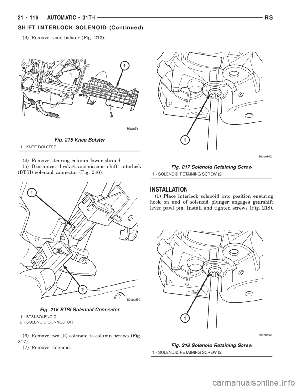
(3) Remove knee bolster (Fig. 215).
(4) Remove steering column lower shroud.
(5) Disconnect brake/transmission shift interlock
(BTSI) solenoid connector (Fig. 216).
(6) Remove two (2) solenoid-to-column screws (Fig.
217).
(7) Remove solenoid.
INSTALLATION
(1) Place interlock solenoid into position ensuring
hook on end of solenoid plunger engages gearshift
lever pawl pin. Install and tighten screws (Fig. 218).
Fig. 215 Knee Bolster
1 - KNEE BOLSTER
Fig. 216 BTSI Solenoid Connector
1 - BTSI SOLENOID
2 - SOLENOID CONNECTOR
Fig. 217 Solenoid Retaining Screw
1 - SOLENOID RETAINING SCREW (2)
Fig. 218 Solenoid Retaining Screw
1 - SOLENOID RETAINING SCREW (2)
21 - 116 AUTOMATIC - 31THRS
SHIFT INTERLOCK SOLENOID (Continued)
Page 3122 of 4284

AUTOMATIC - 41TE
TABLE OF CONTENTS
page page
AUTOMATIC - 41TE
DESCRIPTION..........................159
OPERATION............................159
DIAGNOSIS AND TESTING................159
41TE TRANSAXLE GENERAL DIAGNOSIS . . . 159
ROAD TEST..........................161
HYDRAULIC PRESSURE TESTS..........162
CLUTCH AIR PRESSURE TESTS..........164
TORQUE CONVERTER HOUSING FLUID
LEAKAGE............................164
REMOVAL.............................165
DISASSEMBLY..........................169
ASSEMBLY............................186
INSTALLATION..........................209
SCHEMATICS AND DIAGRAMS.............212
SPECIFICATIONS........................225
SPECIAL TOOLS........................227
ACCUMULATOR
DESCRIPTION..........................232
OPERATION............................233
AUTOSTICK SWITCH
DESCRIPTION..........................233
OPERATION............................233
DRIVING CLUTCHES
DESCRIPTION..........................234
OPERATION............................234
FINAL DRIVE
DESCRIPTION..........................234
OPERATION............................234
DISASSEMBLY..........................235
ASSEMBLY............................240
ADJUSTMENTS.........................243
FLUID
STANDARD PROCEDURE.................246
FLUID LEVEL AND CONDITION CHECK.....246
FLUID AND FILTER SERVICE.............246
GEAR SHIFT CABLE
REMOVAL.............................248
INSTALLATION..........................250
ADJUSTMENTS.........................251
HOLDING CLUTCHES
DESCRIPTION..........................251
OPERATION............................251
INPUT CLUTCH ASSEMBLY
DISASSEMBLY..........................252
ASSEMBLY............................259
OIL PUMP
DESCRIPTION..........................269
OPERATION............................269STANDARD PROCEDURE.................269
OIL PUMP VOLUME CHECK..............269
DISASSEMBLY..........................270
ASSEMBLY............................271
PLANETARY GEARTRAIN
DESCRIPTION..........................271
OPERATION............................271
SEAL - OIL PUMP
REMOVAL.............................271
INSTALLATION..........................272
SHIFT INTERLOCK SOLENOID
DESCRIPTION..........................272
OPERATION............................273
DIAGNOSIS AND TESTING................274
BRAKE/TRANSMISSION SHIFT INTERLOCK
SOLENOID...........................274
REMOVAL.............................274
INSTALLATION..........................275
SOLENOID/PRESSURE SWITCH ASSEMBLY
DESCRIPTION..........................276
OPERATION............................276
REMOVAL.............................277
INSTALLATION..........................277
SPEED SENSOR - INPUT
DESCRIPTION..........................278
OPERATION............................278
REMOVAL.............................279
INSTALLATION..........................279
SPEED SENSOR - OUTPUT
DESCRIPTION..........................280
OPERATION............................280
REMOVAL.............................280
INSTALLATION..........................281
TORQUE CONVERTER
DESCRIPTION..........................281
OPERATION............................284
REMOVAL.............................286
INSTALLATION..........................286
TRANSMISSION CONTROL RELAY
DESCRIPTION..........................287
OPERATION............................287
TRANSMISSION RANGE SENSOR
DESCRIPTION..........................287
OPERATION............................287
REMOVAL.............................288
INSTALLATION..........................288
TORQUE REDUCTION LINK (TRD)
DESCRIPTION..........................289
OPERATION............................289
21 - 158 AUTOMATIC - 41TERS