brake CHRYSLER VOYAGER 2001 Service Manual
[x] Cancel search | Manufacturer: CHRYSLER, Model Year: 2001, Model line: VOYAGER, Model: CHRYSLER VOYAGER 2001Pages: 4284, PDF Size: 83.53 MB
Page 3583 of 4284
(5) Install the cup holder. Align the cup holder
assembly with the track and firmly slide shut to
engage retaining tang.
GLOVE BOX
REMOVAL
(1) Open glove box.
(2) Push in on sides of glove box bin and lower
door.
(3) Pivot glove box downward and disengage hinge
hooks from instrument panel.
(4) Remove glove box.
INSTALLATION
(1) Place glove box in position.
(2) Engage hinge hooks into instrument panel and
pivot glove box upward.
(3) Push in sides of glove box bin and snap glove
box assembly into instrument panel.
(4) Close glove box door.
GLOVE BOX LATCH
REMOVAL
(1) Open glove box.
(2) Push in on sides of glove box bin and lower
door.
(3) Pivot glove box downward and disengage hinge
hooks from instrument panel.
(4) Remove glove box.
(5) Remove the assembly screws.
(6) Disassemble the glove box.
(7) Separate the latch from the glove box assembly.
INSTALLATION
(1) Install the latch onto the glove box assembly.
(2) Assemble the glove box.
(3) Install the assembly screws.
(4) Engage hinge hooks into instrument panel and
pivot glove box upward.
(5) Push in sides of glove box bin and snap glove
box assembly into instrument panel.
(6) Close glove box door.
GLOVE BOX LATCH STRIKER
REMOVAL
(1) Open glove box door.
(2) Remove screws holding lock striker to instru-
ment panel.
(3) Remove glove box latch striker.
INSTALLATION
(1) Install the glove box latch striker.
(2) Install the screws holding latch striker to
instrument panel.
(3) Close glove box door.
INSTRUMENT PANEL
ASSEMBLY
REMOVAL
(1) Disconnect and isolate the battery negative
cable.
(2) Remove the lower console:
(a) Remove six retaining screws.
(b) Pull rearward and disconnect the auxiliary
power outlet.
(c) Remove lower console from vehicle.
(3) Remove the bolts holding the lower supports to
the instrument panel frame.
(4) Remove the bolts holding the lower supports to
the floor pan.
(5) Disconnect the wire connectors from the Pas-
senger Airbag.
(6) Remove the two screws to each right and left
cowl trim covers.
(7) Remove the both left and right side A-pillar
trim covers using a trim stick (special tool #C-4755)
or equivalent gently pry out on the trim covers and
remove.
(8) Remove the glove box:
(a) Push in on sides of glove box bin and lower
door.
(b) Pivot glove box downward and disengage
hinge hooks from instrument panel.
(c) Remove glove box from vehicle.
(9) Disconnect the antenna lead connector from
behind the glove box.
(10) Remove the four screws to the lower steering
column cover.
(11) Remove the eight screws to the plastic knee
blocker reinforcement.
(12) Unclip the Data Link Connector (DLC) from
the instrument panel reinforcement.
(13) Remove one screw to the left side instrument
panel silencer and remove.
(14) Disconnect the left side wiring:
(a) Brake switch.
(b) Main bulkhead connector.
(c) Five harness connectors.
(d) Driver airbag connector.
(15) Remove the two screws to the hood release
handle.
(16) Remove five screws to the left under column
instrument panel reinforcement brace and remove.
RSINSTRUMENT PANEL23 - 203
CUP HOLDER (Continued)
Page 3584 of 4284
(17) Remove the two steering column shroud
retaining screws. Separate the shrouds and remove
from vehicle.
(18) Disconnect the steering column wiring. There
are seven connectors and then unclip the harness
from the column.
(19) Disconnect the ORC harness connector.
(20) Remove the four nuts retaining the steering
column and lower to the floor.
(21) Remove the four nuts attaching the instru-
ment panel to the brake pedal support bracket.
(22) Loosen the left side roll down bolt.
(23) Remove the left side A-pillar retaining bolts.
There are two 13 mm bolts and one 10 mm bolt.
(24) If equipped with a mechanical transmission
range indicator:
(a) Remove the indicator cable loop.
(b) Remove the clip holding gear shift cable end
to the gear selector adapter.
(c) Pull the cable end from gear selector.
(d) Disconnect the clip for the indicator cable
and guide tube from the shift cable bracket and
move out of the way.
(25) Remove the instrument panel top cover. Using
a trim stick or equivalent, gently pry up on the front
edge of the top cover, pull rearward and remove from
vehicle.
(26) Disconnect the right side wire connectors from
the HVAC behind the glove box area and the two
antenna connectors behind the glove box hinge.
(27) Remove the right end cover by pulling out-
board.
(28) Remove the right side A-pillar retaining bolts.
There are two 13 mm bolts and one 10 mm bolt.
(29) Loosen the right side roll down bolt.
(30) Disconnect the two front window defroster
grid wire connectors. One on each side of vehicle.
(31) Remove both the left and right power mirrors:
(a) Using a trim stick or equivalent, gently pry
out on mirror trim cover.
(b) Open door and remove the three torx retain-
ing screws.
(c) Disconnect the wire connector and remove
mirror from the vehicle.
(32) Feed power mirror wire harness inboard
through the A-pillar.
(33) Remove the bolts holding the instrument
panel frame to the dash panel below windshield
opening.
(34) With the help of an assistant remove the
instrument panel from vehicle. Lift the instrument
panel up off the HVAC so you won't damage the seal-
ing surface of the distribution duct.
If the instrument panel is being replaced, transfer
all parts to the new instrument panel assembly.INSTALLATION
(1) With the help of an assistant place the instru-
ment panel into vehicle on roll down bolts. As you
roll the instrument panel up, lift the instrument
panel up so the duct work does not bind or bend and
you can set it down on the HVAC housing to get the
proper seal at the distribution duct. Get one bolt
started in the dash panel.
(2) Install the bolts holding the instrument panel
frame to the dash panel below windshield opening.
(3) Feed power mirror wire harness outboard
through the A-pillar.
(4) Install both the left and right power mirrors:
(a) Connect the wire connector and install the
mirror onto the vehicle.
(b) Install the three torx retaining screws.
(c) Using a firm push, snap the mirror trim
cover into place.
(5) Connect the two front window defroster grid
wire connectors. One on each side of vehicle.
(6) Tighten the right side roll down bolt.
(7) Install the right side A-pillar retaining bolts.
There are two 13 mm bolts and one 10 mm bolt.
(8) Install the right end cover. Position over retain-
ing slots and firmly snap into place.
(9) Connect the right side wire connectors to the
HVAC behind the glove box area and the two
antenna connectors behind the glove box hinge.
(10) Install the instrument panel top cover. Slide
the front edge of the top cover toward dash panel,
and firmly snap down the rear edge of the to cover to
engage clips.
(11) If equipped with a mechanical transmission
range indicator:
(a) Connect the clip for the indicator cable and
guide tube to the shift cable bracket.
(b) Install the cable end to the gear selector.
(c) Install the clip holding the gear shift cable
end to the gear selector adapter.
(d) Install the indicator cable loop.
(12) Install the left side A-pillar retaining bolts.
There are two 13 mm bolts and one 10 mm bolt.
(13) Tighten the left side roll down bolt.
(14) Install the four nuts attaching the instrument
panel to the brake pedal support bracket.
(15) Install the four nuts retaining the steering
column and lower to the floor.
(16) Connect the ORC harness connector.
(17) Connect the steering column wiring. There
are seven connectors and then clip the harness to the
column.
(18) Connect the shrouds and install the two steer-
ing column shroud retaining screws.
(19) Install five screws to the left under column
instrument panel reinforcement brace.
23 - 204 INSTRUMENT PANELRS
INSTRUMENT PANEL ASSEMBLY (Continued)
Page 3585 of 4284
(20) Install the two screws to the hood release
handle.
(21) Connect the left side wiring:
(a) Brake switch.
(b) Main bulkhead connector.
(c) Five harness connectors.
(d) Driver airbag connector.
(22) Install one screw to the left side instrument
panel silencer.
(23) Clip the Data Link Connector (DLC) to the
instrument panel reinforcement.
(24) Install the eight screws to the plastic knee
blocker reinforcement.
(25) Install the four screws to the lower steering
column cover.
(26) Install the glove box:
(a) Install glove box into the vehicle. Line up the
hinges and firmly snap together.
(b) Push in on sides of glove box bin and raise
door.
(27) Install the both left and right side A-pillar
trim covers. Position trim cover over slots and firmly
snap into place.
(28) Install the two screws to each right and left
cowl trim covers.
(29) Connect the wire connectors to the Passenger
Airbag.
(30) Install the bolts holding the lower supports to
the floor pan.
(31) Install the bolts holding the lower supports to
the instrument panel frame.
(32) Install the lower console:
(a) Install lower console to vehicle.
(b) Connect the auxiliary power outlet.
(c) Install the six retaining screws.
(33) Connect the battery negative cable.
INSTRUMENT PANEL CENTER
BEZEL
REMOVAL
(1) Disconnect and isolate the battery negative
cable.
(2) Remove cup holder. Refer to Body, Instrument
Panel, Cup Holder, Removal.
(3) Insert the trim stick (special tool #C-4755) or
equivalent between access cover and center bezel.
(4) Carefully pry the access cover from the instru-
ment panel.
(5) Remove the cup holder track. Refer to Body,
Instrument Panel, Cup Holder, Removal.
(6) Using a trim stick or equivalent, gently pry out
on the edge of the instrument panel center bezel and
pull outward.(7) Disconnect the wire connectors to the accessory
switches and HVAC control.
(8) Remove the instrument panel center bezel from
the vehicle.
INSTALLATION
(1) Install the instrument panel center bezel from
the vehicle.
(2) Connect the wire connectors to the accessory
switches and HVAC control.
(3) Position the center bezel over the retaining
slots and firmly snap the instrument panel center
bezel into place.
(4) Install the cup holder track. Refer to Body,
Instrument Panel, Cup Holder, Installation.
(5) Position the center bezel over the retaining
slots and firmly snap into place.
(6) Install cup holder. Refer to Body, Instrument
Panel, Cup Holder, Installation.
(7) Connect the battery negative cable.
INSTRUMENT PANEL END
COVER
REMOVAL
(1) Open passenger side front door.
(2) Place fingers in end cover grille, and with a
firm outboard pulling motion, disengage clips holding
end cover to instrument panel.
INSTALLATION
(1) Position end cover over retaining slots and
firmly snap into place.
(2) Close passenger side front door.
INSTRUMENT PANEL TOP
COVER
REMOVAL
(1) Remove A-pillar trim. Using a trim stick (spe-
cial tool #C-4755) or equivalent, gently pry out and
remove.
(2) Using a trim stick, disengage clips holding rear
edge of top cover to instrument panel.
NOTE: The Instrument Panel Top Cover may be
hard to unsnap from the instrument panel. Be sure
not to mar, scuff, or damage the instrument panel
pad.
(3) Pull top cover rearward to disengage hooks
holding front of top cover to instrument panel.
(4) Remove top cover from vehicle.
RSINSTRUMENT PANEL23 - 205
INSTRUMENT PANEL ASSEMBLY (Continued)
Page 3708 of 4284

(3) Remove the silencer boot fasteners located
around the base of the lower steering shaft from the
dash panel so that it may be pushed aside.
(4) Remove the brake lamp switch from its mount-
ing bracket. (Refer to 8 - ELECTRICAL/LAMPS/
LIGHTING - EXTERIOR/BRAKE LAMP SWITCH -
REMOVAL).
(5) Disconnect the power brake booster input rod
(push rod) from the pin on the brake pedal arm.
(Refer to 5 - BRAKES - ABS/HYDRAULIC/ME-
CHANICAL/POWER BRAKE BOOSTER - REMOV-
AL).
(6) Remove the three screws that secure the heater
core shield to the left end of the HVAC distribution
housing (Fig. 17).
(7) Pull the heater core shield rearward far enough
to disengage the two location tabs that position the
front of the shield to the receptacles in the two lower
finger formations of the evaporator housing near the
dash panel.
(8) Remove the heater core shield from the distri-
bution housing.
(9) Take the proper precautions to protect the car-
peting below the heater core from spilled engine cool-
ant and have absorbent toweling readily available to
mop up any spills.
(10) Remove the screw that secures the heater core
tube sealing plate to the heater core supply and
return ports (Fig. 18).
(11) Push both heater core tubes simultaneously
toward the dash panel far enough to disengage their
fittings from the heater core supply and return ports.(12) Install plugs in, or tape over the opened
heater core tube fittings and both heater core ports.
(13) Use absorbent toweling to mop up any engine
coolant spills from the preceding operation.
(14) Remove the two screws that secure the heater
core mounting plate to the distribution housing.
(15) While pulling the accelerator pedal upward
(Fig. 19) and pushing the brake pedal downward
(Fig. 20) far enough for clearance, pull the heater
core out of the distribution housing.
Fig. 17 Heater Core Shield
1 - HEATER/ AIR CONDITIONER HOUSING
2 - HEATER CORE SHIELD
3 - DISTRIBUTION HOUSING
4 - SCREWS (3)
5 - LOCATION TABS (2)
Fig. 18 Heater Core
1 - SEALING PLATE
2 - SCREW
3 - SCREWS (2)
4 - HEATER CORE
5 - HEATER CORE TUBES
Fig. 19 Accelerator Pedal
1 - SLIDE HEATER CORE PAST ACCELERATOR PEDAL
24 - 78 PLUMBING - FRONTRS
HEATER CORE (Continued)
Page 3709 of 4284
(16) Use absorbent toweling to mop up any engine
coolant spills from the preceding operation. Also, if
the heater core was leaking, use absorbent toweling
and reach into the heater core opening to mop up
any residual engine coolant within the distribution
housing.
INSTALLATION- HEATER CORE EXTENSION
TUBES
WARNING: REFER TO THE APPLICABLE WARN-
INGS AND CAUTIONS FOR THIS SYSTEM BEFORE
PERFORMING THE FOLLOWING OPERATION.
(Refer to 24 - HEATING & AIR CONDITIONING/
PLUMBING FRONT - WARNING - HEATER PLUMB-
ING).
WARNING: ON VEHICLES EQUIPPED WITH AIR-
BAGS, DISABLE THE AIRBAG SYSTEM BEFORE
ATTEMPTING ANY STEERING WHEEL, STEERING
COLUMN, OR INSTRUMENT PANEL COMPONENT
DIAGNOSIS OR SERVICE. DISCONNECT AND ISO-
LATE THE BATTERY NEGATIVE (GROUND) CABLE,
THEN WAIT TWO MINUTES FOR THE AIRBAG SYS-
TEM CAPACITOR TO DISCHARGE BEFORE PER-
FORMING FURTHER DIAGNOSIS OR SERVICE. THIS
IS THE ONLY SURE WAY TO DISABLE THE AIRBAG
SYSTEM. FAILURE TO TAKE THE PROPER PRE-
CAUTIONS COULD RESULT IN ACCIDENTAL AIR-
BAG DEPLOYMENT AND POSSIBLE PERSONAL
INJURY.(1) Remove the plugs or tape from both heater core
tube fittings and both heater core ports.
(2) Position the heater core tubes and sealing plate
as a unit beneath the instrument panel.
(3) Align the engine compartment ends of both
heater core tubes with the openings in the dash
panel seal and push them simultaneously forward
through the seal far enough to engage the heater
core ends of the tubes with the heater core supply
and return ports (Fig. 16).
(4) Position both heater core tubes and the sealing
plate simultaneously to the heater core supply and
return ports.
(5) The heater core tubes each have a slot that
must be indexed to a location tab within each of the
heater core ports. Adjust the position of the tubes as
required so that the sealing plate fits flush against
the heater core supply and return ports, which indi-
cates that the tubes are properly indexed.
(6) Install and tighten the screw that secures the
heater core tube sealing plate to the heater core sup-
ply and return ports. Tighten the screw to 3 N´m (27
in. lbs.).
(7) Position the heater core shield onto the distri-
bution housing (Fig. 15). Be certain that the two
location tabs on the front of the shield are engaged in
the receptacles in the two lower finger formations of
the evaporator housing near the dash panel.
(8) Install and tighten the three screws that secure
the heater core shield to the left end of the HVAC
distribution housing. Tighten the screws to 2 N´m (17
in. lbs.).
(9) Reinstall the silencer under the driver side end
of the instrument panel. (Refer to 23 - BODY/IN-
STRUMENT PANEL/INSTRUMENT PANEL
SILENCER - INSTALLATION).
(10) Reconnect the heater hoses to the heater hose
tubes. (Refer to 24 - HEATING & AIR CONDITION-
ING/PLUMBING - FRONT/HEATER HOSE -
INSTALLATION).
(11) Reconnect the battery negative cable.
(12) Refill the engine cooling system. (Refer to 7 -
COOLING - STANDARD PROCEDURE - COOLING
SYSTEM REFILL).
Fig. 20 Brake Pedal
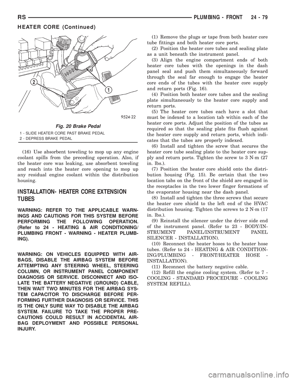
1 - SLIDE HEATER CORE PAST BRAKE PEDAL
2 - DEPRESS BRAKE PEDAL
RSPLUMBING - FRONT24-79
HEATER CORE (Continued)
Page 3710 of 4284
INSTALLATION - HEATER CORE
WARNING: REFER TO THE APPLICABLE WARN-
INGS AND CAUTIONS FOR THIS SYSTEM BEFORE
PERFORMING THE FOLLOWING OPERATION.
(Refer to 24 - HEATING & AIR CONDITIONING/
PLUMBING FRONT - WARNING - HEATER PLUMB-
ING).
WARNING: ON VEHICLES EQUIPPED WITH AIR-
BAGS, DISABLE THE AIRBAG SYSTEM BEFORE
ATTEMPTING ANY STEERING WHEEL, STEERING
COLUMN, OR INSTRUMENT PANEL COMPONENT
DIAGNOSIS OR SERVICE. DISCONNECT AND ISO-
LATE THE BATTERY NEGATIVE (GROUND) CABLE,
THEN WAIT TWO MINUTES FOR THE AIRBAG SYS-
TEM CAPACITOR TO DISCHARGE BEFORE PER-
FORMING FURTHER DIAGNOSIS OR SERVICE. THIS
IS THE ONLY SURE WAY TO DISABLE THE AIRBAG
SYSTEM. FAILURE TO TAKE THE PROPER PRE-
CAUTIONS COULD RESULT IN ACCIDENTAL AIR-
BAG DEPLOYMENT AND POSSIBLE PERSONAL
INJURY.
(1) While pushing the brake pedal downward (Fig.
20) and pulling the accelerator pedal upward (Fig.
19) far enough for clearance, slide the heater core
into the distribution housing.
(2) Install and tighten the two screws that secure
the heater core mounting plate to the distribution
housing (Fig. 18). Tighten the screws to 2 N´m (17 in.
lbs.).
(3) Remove the plugs or tape from the heater core
tube fittings and both heater core ports.
(4) Position both heater core tubes and the sealing
plate simultaneously to the heater core supply and
return ports.
(5) The heater core tubes each have a slot that
must be indexed to a location tab within each of the
heater core ports. Adjust the position of the tubes as
required so that the sealing plate fits flush against
the heater core supply and return ports, which indi-
cates that the tubes are properly indexed.
(6) Install and tighten the screw that secures the
heater core tube sealing plate to the heater core sup-
ply and return ports. Tighten the screw to 3 N´m (27
in. lbs.).
(7) Position the heater core shield onto the distri-
bution housing. Be certain that the two location tabs
on the front of the shield are engaged in the recepta-
cles in the two lower finger formations of the evapo-
rator housing near the dash panel (Fig. 17).
(8) Install and tighten the three screws that secure
the heater core shield to the left end of the HVAC
distribution housing. Tighten the screws to 2 N´m (17
in. lbs.).(9) Reconnect the power brake booster input rod
(push rod) to the pin on the brake pedal arm. (Refer
to 5 - BRAKES - ABS/HYDRAULIC/MECHANICAL/
POWER BRAKE BOOSTER - INSTALLATION).
(10) Reinstall the brake lamp switch into its
mounting bracket. (Refer to 8 - ELECTRICAL/
LAMPS/LIGHTING - EXTERIOR/BRAKE LAMP
SWITCH - INSTALLATION).
(11) Reinstall the silencer boot around the base of
the lower steering shaft on the dash panel.
(12) Reconnect the battery negative cable.
(13) Refill the engine cooling system. (Refer to 7 -
COOLING - STANDARD PROCEDURE - COOLING
SYSTEM REFILL).
(14) Operate sustem for two thermostat cycles to
assure elimination of air in the system.
HEATER HOSE
REMOVAL
There are several heater core plumbing configura-
tions used on this model, depending upon the engine
size and other optional equipment. One plumbing
configuration is used for all 2.4L engines (Fig. 21),
while the 3.3L and 3.8L engines have unique heater
return plumbing on the engine for models with or
without an optional engine oil cooler (Fig. 24) or (Fig.
25). There are also unique plumbing configurations
at the heater core for models with or without the
optional rear heater and air conditioner (Fig. 22) or
(Fig. 23). All models use a combination of formed
steel tubing and rubber hoses. In most cases, the
rubber hose is secured to the steel tubing with a
spring tension clamp.
WARNING: REFER TO THE APPLICABLE WARN-
INGS AND CAUTIONS FOR THIS SYSTEM BEFORE
PERFORMING THE FOLLOWING OPERATION.
(Refer to 24 - HEATING & AIR CONDITIONING/
PLUMBING FRONT - WARNING - HEATER PLUMB-
ING).
(1) Drain the engine cooling system. (Refer to 7 -
COOLING - STANDARD PROCEDURE - COOLING
SYSTEM DRAIN).
(2) Using spring tension clamp pliers, compress
and slide the clamps that secure each end of the
heater hose to the tube or nipple toward the center of
the hose to be removed. Release the clamp when it is
off of the tube or nipple.
24 - 80 PLUMBING - FRONTRS
HEATER CORE (Continued)
Page 3751 of 4284
EMISSIONS CONTROL
TABLE OF CONTENTS
page page
EMISSIONS CONTROL
DESCRIPTION............................1
OPERATION.............................8EVAPORATIVE EMISSIONS.................10
EXHAUST GAS RECIRCULATION............20
ON-BOARD DIAGNOSTICS.................23
EMISSIONS CONTROL
DESCRIPTION - MONITORED COMPONENT
There are several components that will affect vehi-
cle emissions if they malfunction. If one of these com-
ponents malfunctions the Malfunction Indicator
Lamp (Check Engine) will illuminate.
Some of the component monitors are checking for
proper operation of the part. Electrically operated
components now have input (rationality) and output
(functionality) checks. Previously, a component like
the Throttle Position sensor (TPS) was checked by
the PCM for an open or shorted circuit. If one of
these conditions occurred, a DTC was set. Now there
is a check to ensure that the component is working.
This is done by watching for a TPS indication of a
greater or lesser throttle opening than MAP and
engine rpm indicate. In the case of the TPS, if engine
vacuum is high and engine rpm is 1600 or greater
and the TPS indicates a large throttle opening, a
DTC will be set. The same applies to low vacuum
and 1600 rpm.Any component that has an associated
limp in will set a fault after 1 trip with the malfunc-
tion present.
Refer to the Diagnostic Trouble Codes Description
Charts in this section and the appropriate Power-
train Diagnostic Procedure Manual for diagnostic
procedures.
The following is a list of the monitored compo-
nents:
²Comprehensive Components
²Oxygen Sensor Monitor
²Oxygen Sensor Heater Monitor
²Catalyst Monitor
COMPREHENSIVE COMPONENTS
Along with the major monitors, OBD II requires
that the diagnostic system monitor any component
that could affect emissions levels. In many cases,
these components were being tested under OBD I.
The OBD I requirements focused mainly on testing
emissions-related components for electrical opens and
shorts.However, OBD II also requires that inputs from
powertrain components to the PCM be tested for
rationality, and that outputs to powertrain compo-
nents from the PCM be tested forfunctionality.
Methods for monitoring the various Comprehensive
Component monitoring include:
(1) Circuit Continuity
²Open
²Shorted high
²Shorted to ground
(2) Rationality or Proper Functioning
²Inputs tested for rationality
²Outputs tested for functionality
NOTE: Comprehensive component monitors are
continuous. Therefore, enabling conditions do not
apply.
Input RationalityÐWhile input signals to the
PCM are constantly being monitored for electrical
opens and shorts, they are also tested for rationality.
This means that the input signal is compared against
other inputs and information to see if it makes sense
under the current conditions.
PCM sensor inputs that are checked for rationality
include:
²Manifold Absolute Pressure (MAP) Sensor
²Oxygen Sensor (O2S)
²Engine Coolant Temperature (ECT) Sensor
²Camshaft Position (CMP) Sensor
²Vehicle Speed Sensor
²Crankshaft Position (CKP) Sensor
²Intake Air Temperature (IAT) Sensor
²Throttle Position (TPS) Sensor
²Ambient/Battery Temperature Sensors
²Power Steering Switch
²Oxygen Sensor Heater
²Engine Controller
²Brake Switch
²Leak Detection Pump Switch
²P/N Switch
²Trans Controls
Output FunctionalityÐPCM outputs are tested
for functionality in addition to testing for opens and
shorts. When the PCM provides a voltage to an out-
RSEMISSIONS CONTROL25-1
Page 3754 of 4284
PCM calculates the A/F mixture from the output of
the O2S. A low voltage indicates high oxygen content
(lean mixture). A high voltage indicates a low content
of oxygen (rich mixture).
When the upstream O2S detects a lean condition,
there is an abundance of oxygen in the exhaust gas.
A functioning converter would store this oxygen so it
can use it for the oxidation of HC and CO. As the
converter absorbs the oxygen, there will be a lack of
oxygen downstream of the converter. The output of
the downstream O2S will indicate limited activity in
this condition.
As the converter loses the ability to store oxygen,
the condition can be detected from the behavior of
the downstream O2S. When the efficiency drops, no
chemical reaction takes place. This means the con-
centration of oxygen will be the same downstream as
upstream. The output voltage of the downstream
O2S copies the voltage of the upstream sensor. The
only difference is a time lag (seen by the PCM)
between the switching of the O2S's.
To monitor the system, the number of lean-to-rich
switches of upstream and downstream O2S's is
counted. The ratio of downstream switches to
upstream switches is used to determine whether the
catalyst is operating properly. An effective catalyst
will have fewer downstream switches than it has
upstream switches i.e., a ratio closer to zero. For a
totally ineffective catalyst, this ratio will be one-to-
one, indicating that no oxidation occurs in the device.
The system must be monitored so that when cata-
lyst efficiency deteriorates and exhaust emissions
increase to over the legal limit, the MIL (check
engine lamp) will be illuminated.
Monitor OperationÐTo monitor catalyst effi-
ciency, the PCM expands the rich and lean switch
points of the heated oxygen sensor. With extended
switch points, the air/fuel mixture runs richer and
leaner to overburden the catalytic converter. Once
the test is started, the air/fuel mixture runs rich and
lean and the O2 switches are counted. A switch is
counted when an oxygen sensor signal goes from
below the lean threshold to above the rich threshold.
The number of Rear O2 sensor switches is divided by
the number of Front O2 sensor switches to determine
the switching ratio.
The test runs for 20 seconds. As catalyst efficiency
deteriorated over the life of the vehicle, the switch
rate at the downstream sensor approaches that of the
upstream sensor. If at any point during the test
period the switch ratio reaches a predetermined
value, a counter is incremented by one. The monitor
is enabled to run another test during that trip. When
the test fails three times, the counter increments to
three, a malfunction is entered, and a Freeze Frame
is stored. When the counter increments to three dur-ing the next trip, the code is matured and the MIL is
illuminated. If the test passes the first, no further
testing is conducted during that trip.
The MIL is extinguished after three consecutive
good trips. The good trip criteria for the catalyst
monitor is more stringent than the failure criteria. In
order to pass the test and increment one good trip,
the downstream sensor switch rate must be less than
80% of the upstream rate (60% for manual transmis-
sions). The failure percentages are 90% and 70%
respectively.
Enabling ConditionsÐThe following conditions
must typically be met before the PCM runs the cat-
alyst monitor. Specific times for each parameter may
be different from engine to engine.
²Accumulated drive time
²Enable time
²Ambient air temperature
²Barometric pressure
²Catalyst warm-up counter
²Engine coolant temperature
²Accumulated throttle position sensor
²Vehicle speed
²MAP
²RPM
²Engine in closed loop
²Fuel level
Pending ConditionsÐ
²Misfire DTC
²Front Oxygen Sensor Response
²Front Oxygen Sensor Heater Monitor
²Front Oxygen Sensor Electrical
²Rear Oxygen Sensor Rationality (middle check)
²Rear Oxygen Sensor Heater Monitor
²Rear Oxygen Sensor Electrical
²Fuel System Monitor
²All TPS faults
²All MAP faults
²All ECT sensor faults
²Purge flow solenoid functionality
²Purge flow solenoid electrical
²All PCM self test faults
²All CMP and CKP sensor faults
²All injector and ignition electrical faults
²Idle Air Control (IAC) motor functionality
²Vehicle Speed Sensor
²Brake switch
²Intake air temperature
ConflictÐThe catalyst monitor does not run if any
of the following are conditions are present:
²EGR Monitor in progress
²Fuel system rich intrusive test in progress
²EVAP Monitor in progress
²Time since start is less than 60 seconds
²Low fuel level
²Low ambient air temperature
25 - 4 EMISSIONS CONTROLRS
EMISSIONS CONTROL (Continued)
Page 3767 of 4284

PCV VALVE
DESCRIPTION
The PCV valve contains a spring loaded plunger.
The plunger meters the amount of crankcase vapors
routed into the combustion chamber based on intake
manifold vacuum.
OPERATION
When the engine is not operating or during an
engine backfire, the spring forces the plunger back
against the seat. This prevents vapors from flowing
through the valve (Fig. 8).
When the engine is at idle or cruising, high mani-
fold vacuum is present. At these times manifold vac-
uum is able to completely compress the spring and
pull the plunger to the top of the valve (Fig. 9). In
this position there is minimal vapor flow through the
valve.During periods of moderate intake manifold vac-
uum the plunger is only pulled part way back from
the inlet. This results in maximum vapor flow
through the valve (Fig. 10).
DIAGNOSIS AND TESTING - PCV SYSTEM
INSPECTION
WARNING: APPLY PARKING BRAKE AND/OR
BLOCK WHEELS BEFORE PERFORMING ANY TEST
OR ADJUSTMENT WITH THE ENGINE OPERATING.
(1) With engine idling, remove the hose from the
PCV valve. If the valve is not plugged, a hissing
noise will be heard as air passes through the valve. A
strong vacuum should also be felt when a finger is
placed over the valve inlet.
(2) Install hose on PCV valve. Remove the
make-up air hose from the air plenum at the rear of
the engine. Hold a piece of stiff paper (parts tag)
loosely over the end of the make-up air hose.
(3)
After allowing approximately one minute for
crankcase pressure to reduce, the paper should draw up
against the hose with noticeable force. If the engine
does not draw the paper against the grommet after
installing a new valve, replace the PCV valve hose.
(4)Turn the engine off. Remove the PCV valve from
intake manifold. The valve should rattle when shaken.
(5) Replace the PCV valve and retest the system if
it does not operate as described in the preceding
tests.Do not attempt to clean the old PCV valve.
If the valve rattles, apply a light coating of Loctitet
Pipe Sealant With Teflon to the threads. Thread the
PCV valve into the manifold plenum and tighten to 7
N´m (60 in. lbs.) torque.
Fig. 7 PCV VALVE 2.4L
1 - PCV Valve
Fig. 8 Engine Off or Engine Backfire No Vapor Flow
Fig. 9 High Intake Manifold Vacuum Minimal Vapor
Flow
Fig. 10 Moderate Intake Manifold Vacuum Maximum
Vapor Flow
RSEVAPORATIVE EMISSIONS25-17
Page 3779 of 4284
EXHAUST GAS RECIRCULATION
TABLE OF CONTENTS
page page
EXHAUST GAS RECIRCULATION
DESCRIPTION............................3
OPERATION.............................3
VA LV E
DESCRIPTION............................3
OPERATION.............................4REMOVAL...............................4
INSTALLATION............................4
VALVE COOLER
DESCRIPTION............................4
REMOVAL...............................4
INSTALLATION............................5
EXHAUST GAS
RECIRCULATION
DESCRIPTION
The EGR system reduces oxides of nitrogen (NOx)
in the engine exhaust. This is accomplished by allow-
ing a predetermined amount of hot exhaust gas to
recirculate and dilute the incoming fuel/air mixture.
A malfunctioning EGR system can cause engine
stumble, sags, or hesitation, rough idle, engine stall-
ing and poor driveability.
OPERATION
The system consists of:
²An EGR valve assembly. The valve is located on
the rear of the engine above the exhaust manfiold.
²An EGR solenoid.The EGR solenoid controls the
ªon timeº of the EGR valve.
²The ECM operates the EGR solenoid. The ECM
is located inside the vehicle under the instrument
panel.
²An EGR tube connects a passage in the EGR
valve to the rear of the exhaust manifold.
²The vacuum pump supplies vacuum for the EGR
solenoid and the EGR valve. This pump also supplies
vacuum for operation of the power brake boosterb
and the heating and air conditioning system. The
pump is located internally in the front of the engine
block and is driven by the crankshaft gear.
²Vacuum lines and hoses connect the various
components.
When the ECM supplies a variable ground signal
to the EGR solenoid, EGR system operation starts to
occur. The ECM will monitor and determine when tosupply and remove this variable ground signal. This
will depend on inputs from the engine coolant tem-
perature, throttle position and engine speed sensors.
When the variable ground signal is supplied to the
EGR solenoid, vacuum from the vacuum pump will
be allowed to pass through the EGR solenoid and on
to the EGR valve with a connecting hose.
Exhaust gas recirculation will begin in this order
when:
²The ECM determines that EGR system opera-
tion is necessary.
²The engine is running to operate the vacuum
pump.
²A variable ground signal is supplied to the EGR
solenoid.
²Variable vacuum passes through the EGR sole-
noid to the EGR valve.
²The inlet seat (poppet valve) at the bottom of
the EGR valve opens to dilute and recirculate
exhaust gas back into the intake manifold.
The EGR system will be shut down by the ECM
after 60 seconds of continuous engine idling to
improve idle quality.
VA LV E
DESCRIPTION
The EGR system consists of (Fig. 1):
²EGR valve
²EGR tube
²Vacuum hoses
²EGR cooler
²EGR solenoid
RGEXHAUST GAS RECIRCULATION25a-3