sensor CHRYSLER VOYAGER 2001 Service Manual
[x] Cancel search | Manufacturer: CHRYSLER, Model Year: 2001, Model line: VOYAGER, Model: CHRYSLER VOYAGER 2001Pages: 4284, PDF Size: 83.53 MB
Page 1455 of 4284

ENGINE CONTROL MODULE C2 (DIESEL) - BLACK 40 WAYCAV CIRCUIT FUNCTION
82 - -
83 - -
84 - -
85 - -
86 T753 20DG/YL IGNITION SWITCH OUTPUT (START)
87 - -
88 K35 20GY/YL EGR SOLENOID CONTROL
89 K35 20GY/YL EGR SOLENOID CONTROL
90 - -
91 - -
92 - -
93 - -
94 - -
95 - -
96 - -
97 - -
98 - -
99 - -
100 - -
101 - -
102 - -
103 - -
104 - -
105 - -
106 - -
107 - -
108 - -
109 - -
110 - -
111 - -
112 K119 20DB/LG CLUTCH PEDAL UPSTOP SWITCH SENSE
113 - -
114 - -
115 K14 14LB/BR FUEL INJECTOR NO. 4 CONTROL
116 K111 14DB/LB COMMON INJECTOR DRIVER
117 - -
118 K11 14WT/DB FUEL INJECTOR NO. 1 CONTROL
119 K12 14TN FUEL INJECTOR NO. 2 CONTROL
120 K13 14BR/LB FUEL INJECTOR NO. 3 CONTROL
121 - -
ENGINE COOLANT TEMP SENSOR (DIESEL) - BLUE 2 WAYCAV CIRCUIT FUNCTION
1 K2 20TN/BK ENGINE COOLANT TEMPERATURE SENSOR SIGNAL
2 K900 20DB/DG SENSOR GROUND
C
O
N
N
E
C
T
O
R
P
I
N
O
U
T
S
236
CONNECTOR PINOUTS
Page 1456 of 4284

ENGINE OIL PRESSURE SENSOR (DIESEL) - BLACK 3 WAYCAV CIRCUIT FUNCTION
1 F855 20PK/YL SENSOR REFERENCE VOLTAGE A
2 G6 20VT/GY ENGINE OIL PRESSURE SENSOR SIGNAL
3 K936 20BR/YL ENGINE OIL PRESSURE SENSOR GROUND
ENGINE OIL TEMPERATURE SENSOR (DIESEL) - BLACK 2 WAYCAV CIRCUIT FUNCTION
1 K89 20DB/WT ENGINE OIL TEMPERATURE SENSOR SIGNAL
2 K900 20DB/OR SENSOR GROUND
FUEL HEATER (DIESEL) - BLACK 2 WAYCAV CIRCUIT FUNCTION
1 N1 16RD FUEL HEATER RELAY OUTPUT
2 Z201 18RD GROUND
FUEL INJECTOR NO. 1 (DIESEL) - BLACK 2 WAYCAV CIRCUIT FUNCTION
1 K111 14DB/LB COMMON INJECTOR DRIVER
2 K11 14WT/DB FUEL INJECTOR NO. 1 CONTROL
FUEL INJECTOR NO. 2 (DIESEL) - BLACK 2 WAYCAV CIRCUIT FUNCTION
1 K111 14DB/LB COMMON INJECTOR DRIVER
2 K12 14TN FUEL INJECTOR NO. 2 CONTROL
C
O
N
N
E
C
T
O
R
P
I
N
O
U
T
S
237
CONNECTOR PINOUTS
Page 1457 of 4284
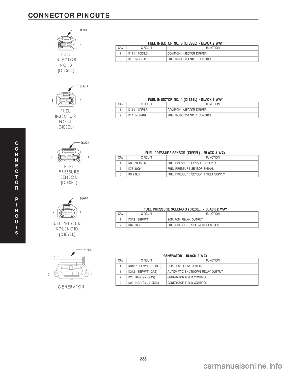
FUEL INJECTOR NO. 3 (DIESEL) - BLACK 2 WAYCAV CIRCUIT FUNCTION
1 K111 14DB/LB COMMON INJECTOR DRIVER
2 K13 14BR/LB FUEL INJECTOR NO. 3 CONTROL
FUEL INJECTOR NO. 4 (DIESEL) - BLACK 2 WAYCAV CIRCUIT FUNCTION
1 K111 14DB/LB COMMON INJECTOR DRIVER
2 K14 14LB/BR FUEL INJECTOR NO. 4 CONTROL
FUEL PRESSURE SENSOR (DIESEL) - BLACK 3 WAYCAV CIRCUIT FUNCTION
1 K80 20DB/TN FUEL PRESSURE SENSOR GROUND
2 K78 20GY FUEL PRESSURE SENSOR SIGNAL
3 K9 20LB FUEL PRESSURE SENSOR 5 VOLT SUPPLY
FUEL PRESSURE SOLENOID (DIESEL) - BLACK 2 WAYCAV CIRCUIT FUNCTION
1 K342 16BR/WT ECM/PCM RELAY OUTPUT
2 K87 16BR FUEL PRESSURE SOLENOID CONTROL
GENERATOR - BLACK 2 WAYCAV CIRCUIT FUNCTION
1 K342 16BR/WT (DIESEL) ECM/PCM RELAY OUTPUT
1 K342 16BR/WT (GAS) AUTOMATIC SHUTDOWN RELAY OUTPUT
2 K20 18BR/GY (GAS) GENERATOR FIELD CONTROL
2 K20 14BR/GY (DIESEL) GENERATOR FIELD CONTROL
C
O
N
N
E
C
T
O
R
P
I
N
O
U
T
S
238
CONNECTOR PINOUTS
Page 1459 of 4284
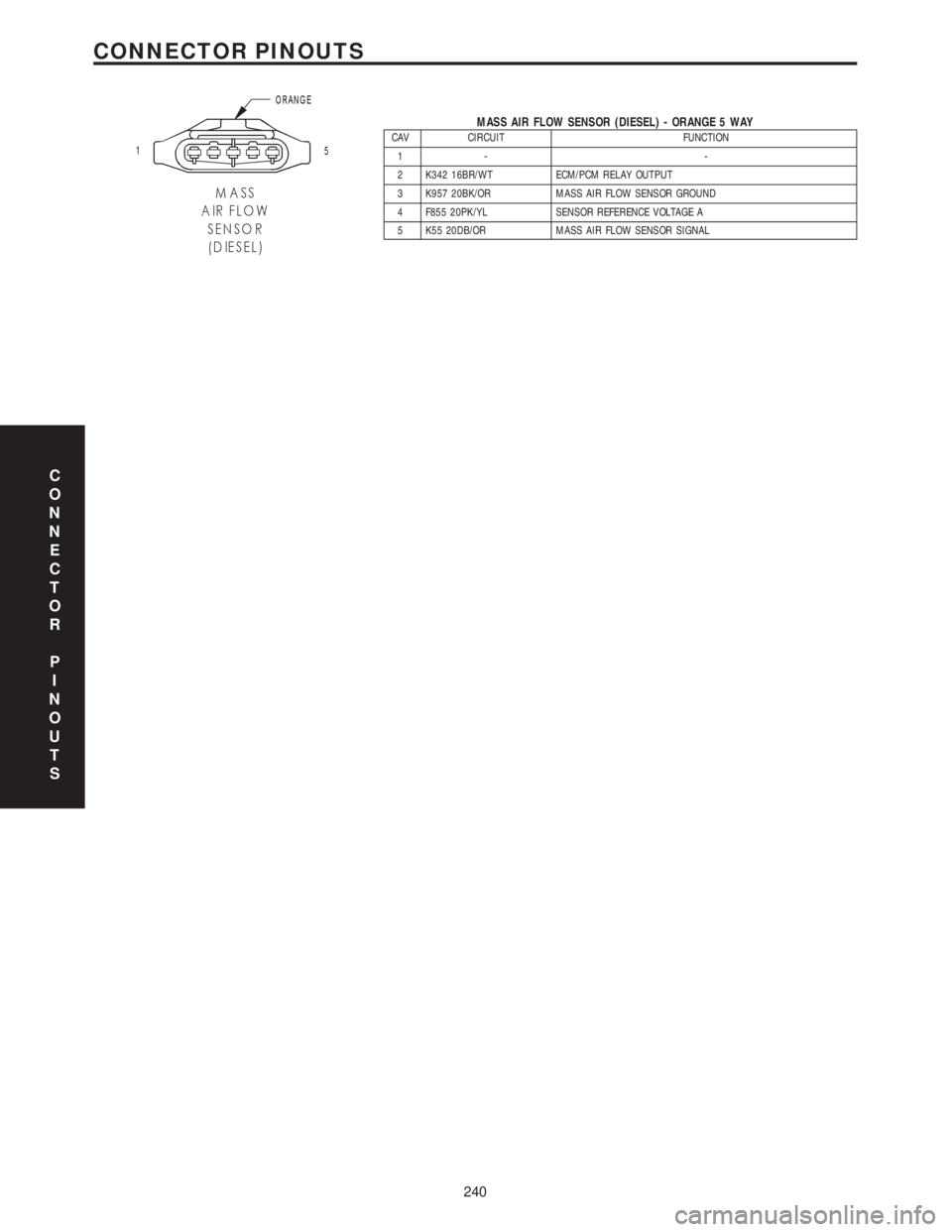
MASS AIR FLOW SENSOR (DIESEL) - ORANGE 5 WAYCAV CIRCUIT FUNCTION
1- -
2 K342 16BR/WT ECM/PCM RELAY OUTPUT
3 K957 20BK/OR MASS AIR FLOW SENSOR GROUND
4 F855 20PK/YL SENSOR REFERENCE VOLTAGE A
5 K55 20DB/OR MASS AIR FLOW SENSOR SIGNAL
C
O
N
N
E
C
T
O
R
P
I
N
O
U
T
S
240
CONNECTOR PINOUTS
Page 1463 of 4284
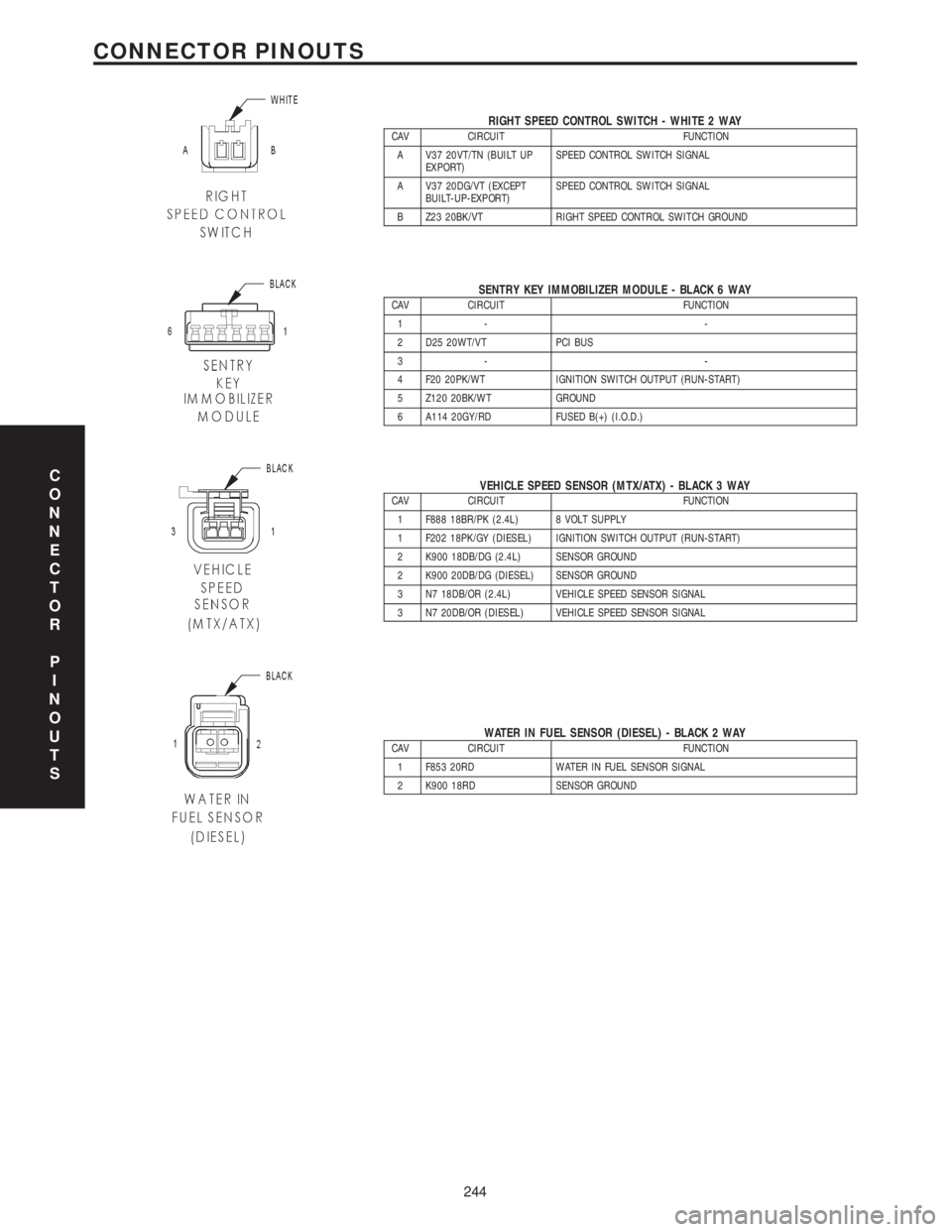
RIGHT SPEED CONTROL SWITCH - WHITE 2 WAYCAV CIRCUIT FUNCTION
A V37 20VT/TN (BUILT UP
EXPORT)SPEED CONTROL SWITCH SIGNAL
A V37 20DG/VT (EXCEPT
BUILT-UP-EXPORT)SPEED CONTROL SWITCH SIGNAL
B Z23 20BK/VT RIGHT SPEED CONTROL SWITCH GROUND
SENTRY KEY IMMOBILIZER MODULE - BLACK 6 WAYCAV CIRCUIT FUNCTION
1- -
2 D25 20WT/VT PCI BUS
3- -
4 F20 20PK/WT IGNITION SWITCH OUTPUT (RUN-START)
5 Z120 20BK/WT GROUND
6 A114 20GY/RD FUSED B(+) (I.O.D.)
VEHICLE SPEED SENSOR (MTX/ATX) - BLACK 3 WAYCAV CIRCUIT FUNCTION
1 F888 18BR/PK (2.4L) 8 VOLT SUPPLY
1 F202 18PK/GY (DIESEL) IGNITION SWITCH OUTPUT (RUN-START)
2 K900 18DB/DG (2.4L) SENSOR GROUND
2 K900 20DB/DG (DIESEL) SENSOR GROUND
3 N7 18DB/OR (2.4L) VEHICLE SPEED SENSOR SIGNAL
3 N7 20DB/OR (DIESEL) VEHICLE SPEED SENSOR SIGNAL
WATER IN FUEL SENSOR (DIESEL) - BLACK 2 WAYCAV CIRCUIT FUNCTION
1 F853 20RD WATER IN FUEL SENSOR SIGNAL
2 K900 18RD SENSOR GROUND
C
O
N
N
E
C
T
O
R
P
I
N
O
U
T
S
244
CONNECTOR PINOUTS
Page 1523 of 4284
REMOVAL - STEERING KNUCKLE
(1) Raise vehicle on jack stands or centered on a
frame contact type hoist. Refer to Hoisting in Lubri-
cation And Maintenance.
(2) Remove the wheel and tire assembly from the
vehicle.
(3) Remove the cotter pin, nut lock and spring
washer from the end of the stub axle and hub nut
(Fig. 8).
(4) Have a helper apply the vehicle's brakes to
keep hub from turning,loosen and removethe hub
nut (Fig. 8).
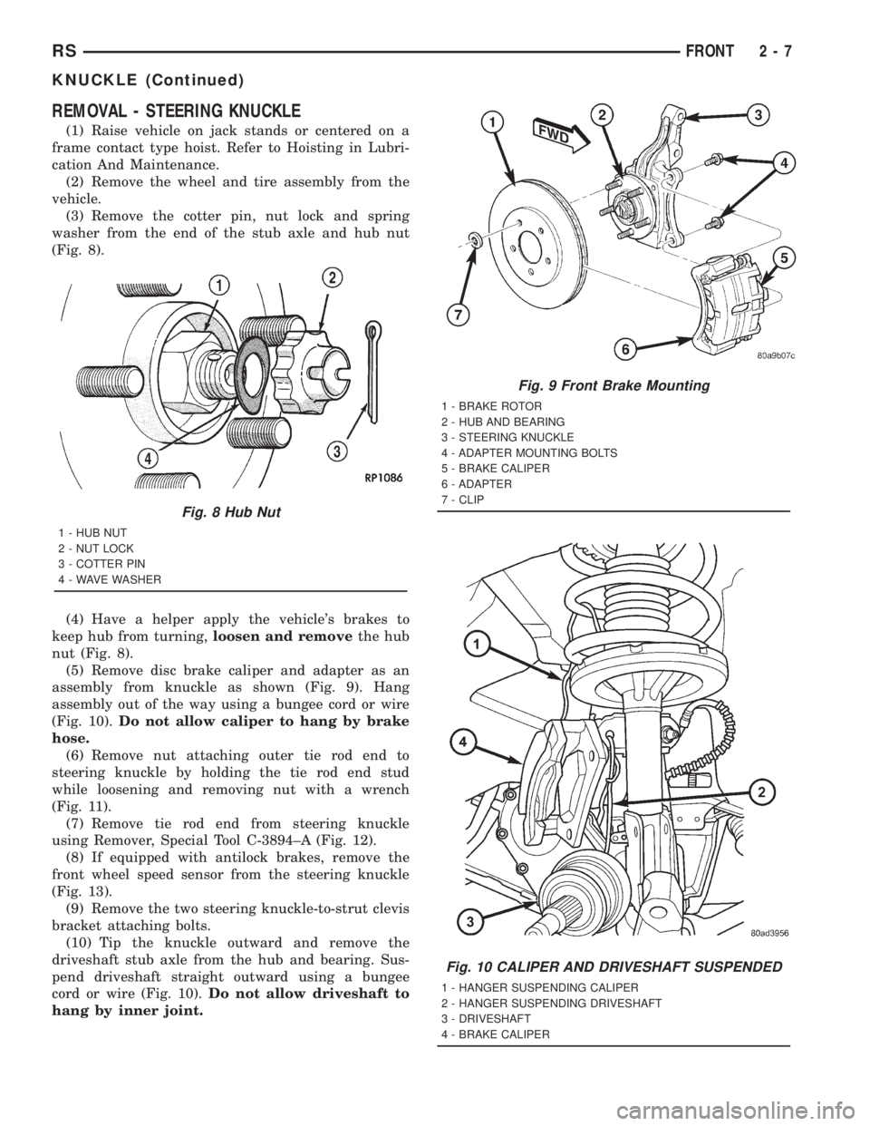
(5) Remove disc brake caliper and adapter as an
assembly from knuckle as shown (Fig. 9). Hang
assembly out of the way using a bungee cord or wire
(Fig. 10).Do not allow caliper to hang by brake
hose.
(6) Remove nut attaching outer tie rod end to
steering knuckle by holding the tie rod end stud
while loosening and removing nut with a wrench
(Fig. 11).
(7) Remove tie rod end from steering knuckle
using Remover, Special Tool C-3894±A (Fig. 12).
(8) If equipped with antilock brakes, remove the
front wheel speed sensor from the steering knuckle
(Fig. 13).
(9) Remove the two steering knuckle-to-strut clevis
bracket attaching bolts.
(10) Tip the knuckle outward and remove the
driveshaft stub axle from the hub and bearing. Sus-
pend driveshaft straight outward using a bungee
cord or wire (Fig. 10).Do not allow driveshaft to
hang by inner joint.
Fig. 8 Hub Nut
1 - HUB NUT
2 - NUT LOCK
3 - COTTER PIN
4 - WAVE WASHER
Fig. 9 Front Brake Mounting
1 - BRAKE ROTOR
2 - HUB AND BEARING
3 - STEERING KNUCKLE
4 - ADAPTER MOUNTING BOLTS
5 - BRAKE CALIPER
6 - ADAPTER
7 - CLIP
Fig. 10 CALIPER AND DRIVESHAFT SUSPENDED
1 - HANGER SUSPENDING CALIPER
2 - HANGER SUSPENDING DRIVESHAFT
3 - DRIVESHAFT
4 - BRAKE CALIPER
RSFRONT2-7
KNUCKLE (Continued)
Page 1524 of 4284
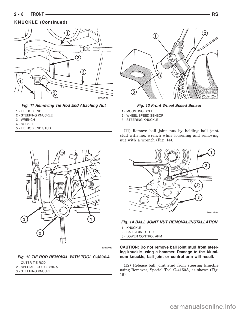
(11) Remove ball joint nut by holding ball joint
stud with hex wrench while loosening and removing
nut with a wrench (Fig. 14).
CAUTION: Do not remove ball joint stud from steer-
ing knuckle using a hammer. Damage to the Alumi-
num knuckle, ball joint or control arm will result.
(12) Release ball joint stud from steering knuckle
using Remover, Special Tool C-4150A, as shown (Fig.
15).
Fig. 11 Removing Tie Rod End Attaching Nut
1 - TIE ROD END
2 - STEERING KNUCKLE
3 - WRENCH
4 - SOCKET
5 - TIE ROD END STUD
Fig. 12 TIE ROD REMOVAL WITH TOOL C-3894-A
1 - OUTER TIE ROD
2 - SPECIAL TOOL C-3894-A
3 - STEERING KNUCKLE
Fig. 13 Front Wheel Speed Sensor
1 - MOUNTING BOLT
2 - WHEEL SPEED SENSOR
3 - STEERING KNUCKLE
Fig. 14 BALL JOINT NUT REMOVAL/INSTALLATION
1 - KNUCKLE
2 - BALL JOINT STUD
3 - LOWER CONTROL ARM
2 - 8 FRONTRS
KNUCKLE (Continued)
Page 1526 of 4284
(5) Install steering knuckle in clevis bracket of
strut damper assembly. Install the strut clevis-to-
steering knuckle attaching bolts. Tighten both bolts
to a torque of 81 N´m (60 ft. lbs.) plus an additional
1/4 (90É) turn.
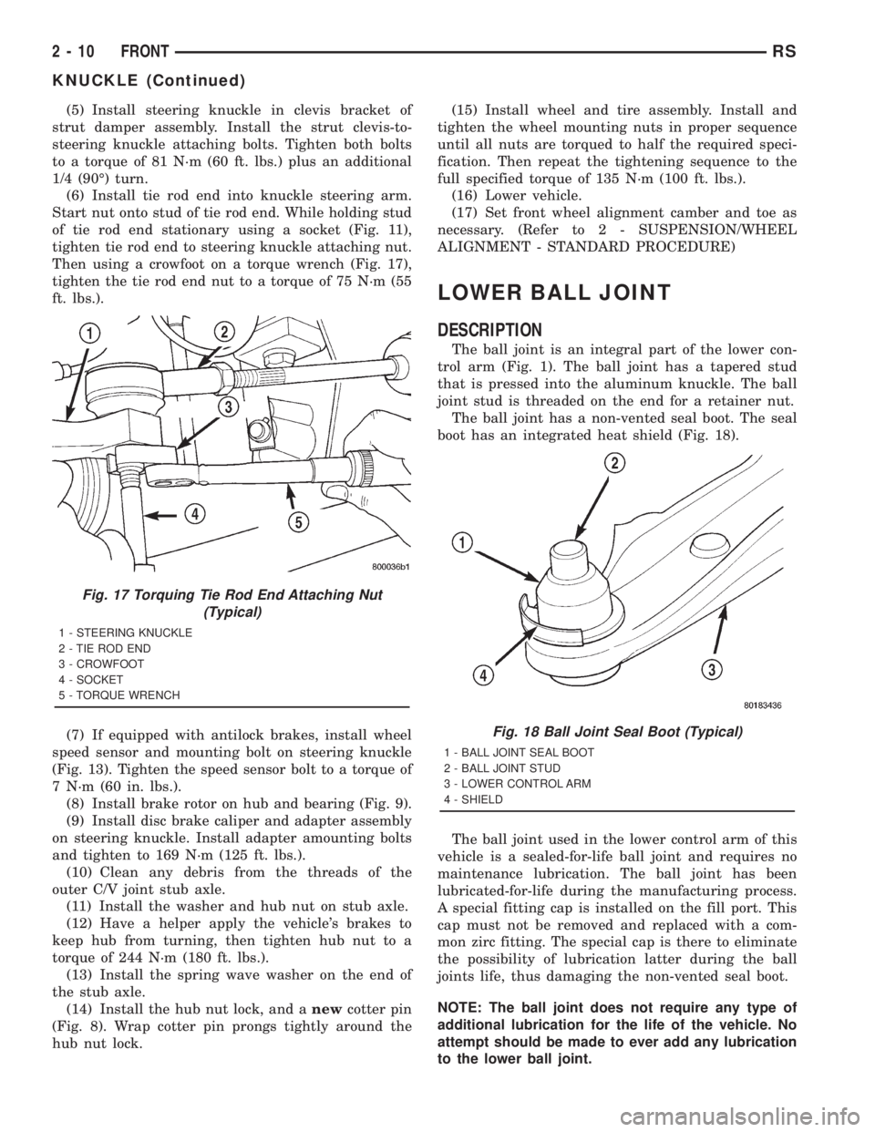
(6) Install tie rod end into knuckle steering arm.
Start nut onto stud of tie rod end. While holding stud
of tie rod end stationary using a socket (Fig. 11),
tighten tie rod end to steering knuckle attaching nut.
Then using a crowfoot on a torque wrench (Fig. 17),
tighten the tie rod end nut to a torque of 75 N´m (55
ft. lbs.).
(7) If equipped with antilock brakes, install wheel
speed sensor and mounting bolt on steering knuckle
(Fig. 13). Tighten the speed sensor bolt to a torque of
7 N´m (60 in. lbs.).
(8) Install brake rotor on hub and bearing (Fig. 9).
(9) Install disc brake caliper and adapter assembly
on steering knuckle. Install adapter amounting bolts
and tighten to 169 N´m (125 ft. lbs.).
(10) Clean any debris from the threads of the
outer C/V joint stub axle.
(11) Install the washer and hub nut on stub axle.
(12) Have a helper apply the vehicle's brakes to
keep hub from turning, then tighten hub nut to a
torque of 244 N´m (180 ft. lbs.).
(13) Install the spring wave washer on the end of
the stub axle.
(14) Install the hub nut lock, and anewcotter pin
(Fig. 8). Wrap cotter pin prongs tightly around the
hub nut lock.(15) Install wheel and tire assembly. Install and
tighten the wheel mounting nuts in proper sequence
until all nuts are torqued to half the required speci-
fication. Then repeat the tightening sequence to the
full specified torque of 135 N´m (100 ft. lbs.).
(16) Lower vehicle.
(17) Set front wheel alignment camber and toe as
necessary. (Refer to 2 - SUSPENSION/WHEEL
ALIGNMENT - STANDARD PROCEDURE)
LOWER BALL JOINT
DESCRIPTION
The ball joint is an integral part of the lower con-
trol arm (Fig. 1). The ball joint has a tapered stud
that is pressed into the aluminum knuckle. The ball
joint stud is threaded on the end for a retainer nut.
The ball joint has a non-vented seal boot. The seal
boot has an integrated heat shield (Fig. 18).
The ball joint used in the lower control arm of this
vehicle is a sealed-for-life ball joint and requires no
maintenance lubrication. The ball joint has been
lubricated-for-life during the manufacturing process.
A special fitting cap is installed on the fill port. This
cap must not be removed and replaced with a com-
mon zirc fitting. The special cap is there to eliminate
the possibility of lubrication latter during the ball
joints life, thus damaging the non-vented seal boot.
NOTE: The ball joint does not require any type of
additional lubrication for the life of the vehicle. No
attempt should be made to ever add any lubrication
to the lower ball joint.
Fig. 17 Torquing Tie Rod End Attaching Nut
(Typical)
1 - STEERING KNUCKLE
2 - TIE ROD END
3 - CROWFOOT
4 - SOCKET
5 - TORQUE WRENCH
Fig. 18 Ball Joint Seal Boot (Typical)
1 - BALL JOINT SEAL BOOT
2 - BALL JOINT STUD
3 - LOWER CONTROL ARM
4 - SHIELD
2 - 10 FRONTRS
KNUCKLE (Continued)
Page 1536 of 4284

arately for each corner or side of the vehicle depend-
ing on optional equipment and type of vehicle
service. If the coil springs require replacement, be
sure that the springs are replaced with springs meet-
ing the correct load rating and spring rate for the
vehicle and its specific options.
OPERATION - STRUT ASSEMBLY
The strut assembly cushions the ride of the vehicle,
controlling vibration, along with jounce and rebound
of the suspension.
The coil spring controls ride quality and maintains
proper ride height.
The spring isolators isolate the coil spring at the
top and bottom from coming into metal-to-metal con-
tact with the upper seat and strut.
The jounce bumper limits suspension travel and
metal-to-metal contact under full jounce condition.
The strut dampens jounce and rebound motions of
the coil spring and suspension.
During steering maneuvers, the strut assembly
(through a pivot bearing in the upper strut mount)
and steering knuckle (through the lower ball joint)
turn as an assembly.
DIAGNOSIS AND TESTING - STRUT ASSEMBLY
(FRONT)
(1) Inspect for damaged or broken coil springs
(Fig. 39).
(2) Inspect for torn or damaged strut assembly
dust boots (Fig. 39).
(3) Inspect the coil spring isolator on the lower
spring seat for any signs of damage or deterioration.
(4) Lift dust boot (Fig. 40) and inspect strut
assembly for evidence of fluid running from the
upper end of fluid reservoir. (Actual leakage will be a
stream of fluid running down the side and dripping
off lower end of unit). A slight amount of seepage
between the strut rod and strut shaft seal is not
unusual and does not affect performance of the strut
assembly (Fig. 40). Also inspect jounce bumpers for
signs of damage or deterioration.
REMOVAL - STRUT ASSEMBLY
WARNING: DO NOT REMOVE THE NUT FROM THE
STRUT ROD WHILE STRUT ASSEMBLY IS
INSTALLED IN VEHICLE, OR BEFORE STRUT
ASSEMBLY SPRING IS COMPRESSED.
(1) Raise the vehicle. See Hoisting in Lubrication
and Maintenance.
(2) Remove the wheel and tire assembly from loca-
tion on front of vehicle requiring strut removal.(3) If both strut assemblies are to be removed,
mark the strut assemblies right or left according to
which side of the vehicle they were removed from.
(4) Remove the hydraulic brake hose routing
bracket and the speed sensor cable routing bracket
from the strut damper brackets (Fig. 41).
Fig. 40 Strut Assembly Leakage Inspection (Typical)
1 - DUST BOOT
2 - STRUT SHAFT
3 - STRUT FLUID RESERVOIR
4 - INSPECT THIS AREA FOR EVIDENCE OF EXCESSIVE FLUID
LEAKAGE
Fig. 41 Brake Hose And Speed Sensor Cable
Routing
1 - STRUT DAMPER
2 - WHEEL SPEED SENSOR CABLE
3 - ROUTING BRACKET
4 - HYDRAULIC BRAKE HOSE
5 - ATTACHING BOLT
6 - ROUTING BRACKET
2 - 20 FRONTRS
STRUT (Continued)
Page 1546 of 4284
body, Install the mounting bolts (Fig. 3). Tighten the
four mounting bolts to 61 N´m (45 ft. lbs.) torque.
(9) Raise or lower the jack until shock absorber
lower eye aligns with threads in axle housing. Install
shock absorber lower mounting bolt. Do not fully
tighten bolt at this time.
(10) Lower the vehicle and remove hoist arms and
block of wood from under vehicle.
(11) Tighten the spring front pivot bolt to 156 N´m
(115 ft. lbs.) torque.
(12) Tighten the lower shock absorber mounting
bolt to 102 N´m (75 ft. lbs.) torque.
HUB / BEARING
DESCRIPTION
The rear wheel bearing and rear wheel hub of this
vehicle are a one-piece sealed unit, or hub and bear-
ing unit type assembly. The hub and bearing is
mounted to the center of the rear axle using 4
mounting bolts. It has five wheel mounting studs on
the hub flange.
All-Wheel-Drive vehicles have a hub and bearing
unit with a splined hole in the center of the hub for
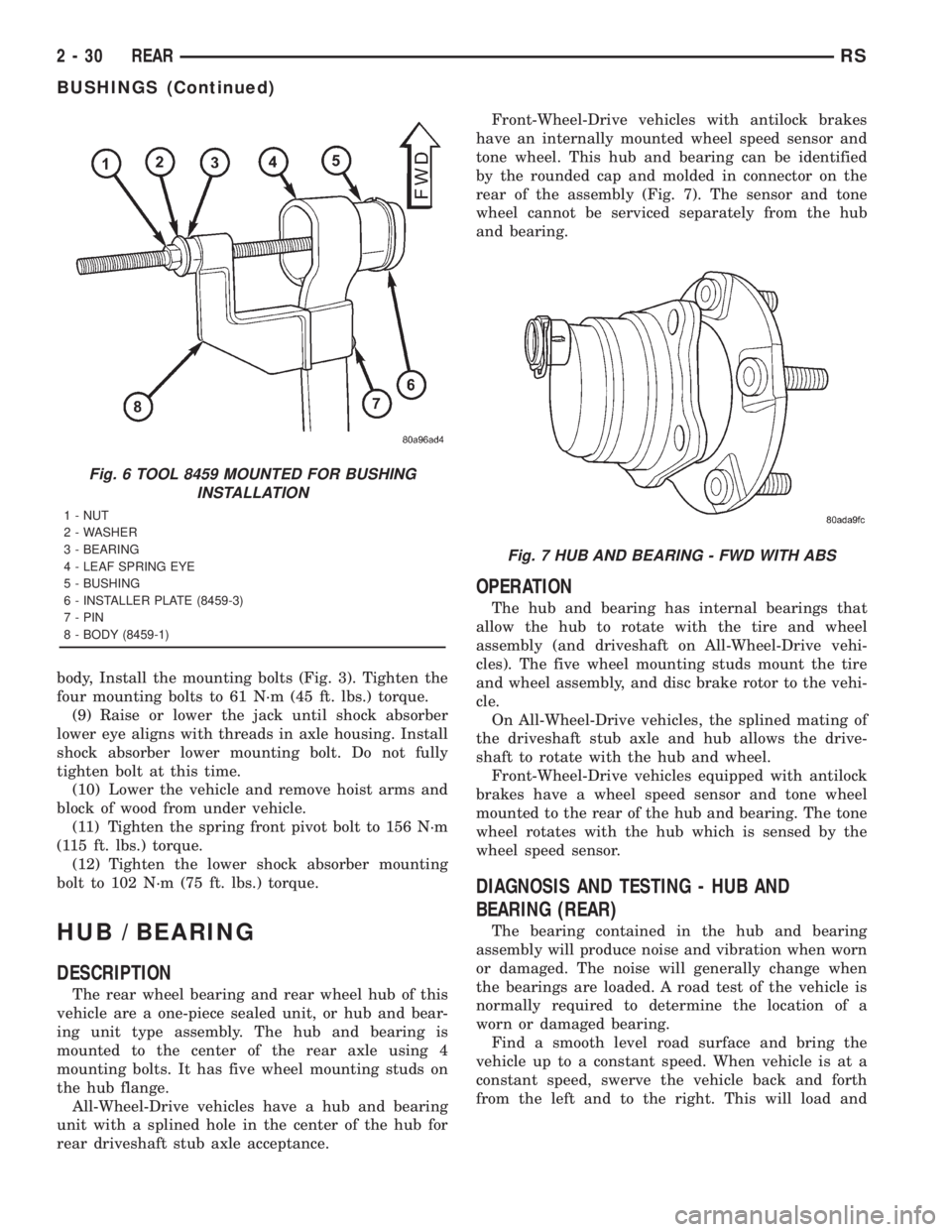
rear driveshaft stub axle acceptance.Front-Wheel-Drive vehicles with antilock brakes
have an internally mounted wheel speed sensor and
tone wheel. This hub and bearing can be identified
by the rounded cap and molded in connector on the
rear of the assembly (Fig. 7). The sensor and tone
wheel cannot be serviced separately from the hub
and bearing.
OPERATION
The hub and bearing has internal bearings that
allow the hub to rotate with the tire and wheel
assembly (and driveshaft on All-Wheel-Drive vehi-
cles). The five wheel mounting studs mount the tire
and wheel assembly, and disc brake rotor to the vehi-
cle.
On All-Wheel-Drive vehicles, the splined mating of
the driveshaft stub axle and hub allows the drive-
shaft to rotate with the hub and wheel.
Front-Wheel-Drive vehicles equipped with antilock
brakes have a wheel speed sensor and tone wheel
mounted to the rear of the hub and bearing. The tone
wheel rotates with the hub which is sensed by the
wheel speed sensor.
DIAGNOSIS AND TESTING - HUB AND
BEARING (REAR)
The bearing contained in the hub and bearing
assembly will produce noise and vibration when worn
or damaged. The noise will generally change when
the bearings are loaded. A road test of the vehicle is
normally required to determine the location of a
worn or damaged bearing.
Find a smooth level road surface and bring the
vehicle up to a constant speed. When vehicle is at a
constant speed, swerve the vehicle back and forth
from the left and to the right. This will load and
Fig. 6 TOOL 8459 MOUNTED FOR BUSHING
INSTALLATION
1 - NUT
2 - WASHER
3 - BEARING
4 - LEAF SPRING EYE
5 - BUSHING
6 - INSTALLER PLATE (8459-3)
7 - PIN
8 - BODY (8459-1)
Fig. 7 HUB AND BEARING - FWD WITH ABS
2 - 30 REARRS
BUSHINGS (Continued)