window CHRYSLER VOYAGER 2001 Service Manual
[x] Cancel search | Manufacturer: CHRYSLER, Model Year: 2001, Model line: VOYAGER, Model: CHRYSLER VOYAGER 2001Pages: 4284, PDF Size: 83.53 MB
Page 6 of 4284
TABLE OF CONTENTS - Continued
3.18.3SYSTEM INHIBITORS.....................................26
3.19REAR WINDOW DEFOG/HEATED MIRROR/FRONT WIPER DE-ICE........26
3.20VEHICLE THEFT SECURITY SYSTEM.................................26
3.20.1BASE ALARM SYSTEM....................................26
3.20.2THATCHAM ALARM SYSTEM...............................27
3.21WIPER SYSTEM...................................................27
3.21.1FRONT WIPER...........................................27
3.21.2SPEED SENSITIVE INTERMITTENT WIPE MODE..............27
3.21.3PULSE WIPE.............................................27
3.21.4PARK AFTER IGNITION OFF................................27
3.21.5WIPE AFTER WASH.......................................27
3.21.6REAR WIPER............................................27
3.21.7SPEED SENSITIVE INTERMITTENT WIPE MODE..............27
3.21.8WIPE AFTER WASH.......................................28
3.22USING THE DRBIIIT.......................................28
3.22.1DRBIIITERROR MESSAGES...............................28
3.22.2DRBIIITDOES NOT POWER UP (BLANK SCREEN).............28
3.22.3DISPLAY IS NOT VISIBLE..................................28
4.0 DISCLAIMERS, SAFETY, WARNINGS......................................28
4.1DISCLAIMERS.....................................................28
4.2SAFETY..........................................................28
4.2.1TECHNICIAN SAFETY INFORMATION........................28
4.2.2VEHICLE PREPARATION FOR TESTING......................29
4.2.3SERVICING SUB-ASSEMBLIES.............................29
4.2.4DRBIIITSAFETY INFORMATION............................29
4.3WARNINGS.......................................................29
4.3.1VEHICLE DAMAGE WARNINGS.............................29
4.3.2ROAD TESTING A COMPLAINT VEHICLE.....................29
5.0 REQUIRED TOOLS AND EQUIPMENT.....................................30
6.0 GLOSSARY OF TERMS..................................................30
7.0 DIAGNOSTIC INFORMATION AND PROCEDURES...........................31
AIRBAG
FCM, ORC RUN ONLY DRIVER OPEN - ACTIVE.............................32
FCM, ORC RUN ONLY DRIVER OVER CURRENT - ACTIVE....................32
FCM, ORC RUN ONLY DRIVER OVER TEMP - ACTIVE.......................32
FCM, ORC RUN ONLY DRIVER OVER VOLT - ACTIVE........................32
FCM, ORC RUN ONLY DRIVER SHORT TO GROUND - ACTIVE................32
ORC, LOSS OF IGNITION RUN ONLY - ACTIVE..............................32
FCM, ORC RUN ONLY DRIVER OPEN - STORED............................37
FCM, ORC RUN ONLY DRIVER OVER CURRENT - STORED..................37
FCM, ORC RUN ONLY DRIVER OVER TEMP - STORED......................37
FCM, ORC RUN ONLY DRIVER OVER VOLT - STORED.......................37
FCM, ORC RUN ONLY DRIVER SHORT TO GROUND - STORED...............37
FCM, ORC RUN-START DRIVER OPEN - STORED...........................37
FCM, ORC RUN-START DRIVER OVER CURRENT - STORED.................37
FCM, ORC RUN-START DRIVER OVER TEMP - STORED.....................37
FCM, ORC RUN-START DRIVER OVER VOLT - STORED......................37
FCM, ORC RUN-START DRIVER SHORT TO GROUND - STORED..............37
iii
Page 30 of 4284
1.0 INTRODUCTION
The procedures contained in this manual include
all the specifications, instructions and graphics
needed to diagnose 2001 body system problems. The
diagnostics in this manual are based on the failure
condition or symptom being present at the time of
diagnosis.
Please follow the recommendations below when
choosing your diagnostic path.
1. First make sure the DRBIIItis communicating
with the appropriate modules; i.e., if the
DRBIIItdisplays a ªNo Responseº or a ªBus6
Signals Openº condition, you must diagnose that
first.
2. Read DTC's (diagnostic trouble codes) with the
DRBIIIt.
3. If no DTC's are present, identify the customer
complaint.
4. Once the DTC or customer complaint is identi-
fied, locate the matching test in the Table of
Contents and begin to diagnose the symptom.
All component location views are in Section 8.0. All
connector pinouts are in Section 9.0. All schematics
are in Section 10.0. All Charts and Graphs are in
Section 11.0.
An * placed before the symptom description indi-
cated a customer complaint.
When repairs are required, refer to the appropri-
ate service information for the proper removal and
repair procedure.
Diagnostic procedures change every year. New
diagnostic systems may be added: carryover systems
may be enhanced. READ THIS MANUAL BEFORE
TRYING TO DIAGNOSE A VEHICLE DIAGNOS-
TIC TROUBLE CODE. It is recommended that you
review the entire manual to become familiar with all
the new and changed diagnostic procedures.
This book reflects many suggested changes from
readers of past issues. After using this book, if you
have any comments or suggestions, please fill out
the form in the back of this book and mail it back to
us.
1.1 SYSTEM COVERAGE
This diagnostic procedures manual covers all
2001 Chrysler Voyager and Caravan vehicles. This
diagnostic procedures manual also covers both left
hand drive (LHD) and right hand drive (RHD)
vehicles. There may be some slight differences in
the location views of components. If the location
views shown are on a LHD vehicle, a RHD vehicle
will be symmetrically opposite.
1.2 SIX-STEP TROUBLESHOOTING
PROCEDURE
Diagnosis of the body system is done in six basic
steps:
²verification of complaint
²verification of any related symptoms
²symptom analysis
²problem isolation
²repair of isolated problem
²verification of proper operation
2.0 IDENTIFICATION OF
SYSTEM
The vehicle systems that are part of the ªbodyº
system are:
²Airbag
²Audio
²Cabin Heater
²Chime
²Communication
²Door Ajar System
²Electrically heated system
²Exterior lighting
²Heating and A/C
²Instrument Cluster
²Interior Lighting
²Manual Temperature Control
²Memory Seat
²Overhead Console
²Power Door Lock/RKE
²Power Folding Mirrors
²Power Sliding Doors
²Power Liftgate
²Power windows
²Vehicle Theft Security System (VTSS)
²Windshield Wiper and Washer
3.0 SYSTEM DESCRIPTION AND
FUNCTIONAL OPERATION
The body system on the 2001 RG consists of a
combination of modules that communicate over the
PCI bus (Programmable Communication Interface
multiplex system). Through the PCI bus, informa-
tion about the operation of vehicle components and
circuits is relayed quickly to the appropriate mod-
ule(s). All modules receive all the information trans-
1
GENERAL INFORMATION
Page 43 of 4284
EATX power
The electronic automatic 4 speed transmission
module is powered when the ignition switch is in
the UNLOCK, RUN or START positions. This cir-
cuit is electronically controlled and continuously
monitored for malfunctions. Power is supplied
through pin 27 of the FCM connector.
Front washer motor
The front washer switch is a direct input to the
BCM. The BCM sends a PCI Bus message to the
FCM informing it of a request to wash. The front
washer motor is then powered through low side
control inside the FCM. This circuit is electronically
controlled and continuously monitored for malfunc-
tions. In addition, the FCM electronically protects
the washer motor from system voltages higher than
16 volts by automatically switching off the low side
circuit. The low side circuit is connected to pin 45 in
the FCM connector.
Rear washer motor
The rear washer switch is a direct input to the
BCM. The BCM sends a PCI Bus message to the
FCM informing it of a request to wash. The rear
washer motor is then powered through low side
control inside the FCM. This circuit is electronically
controlled and continuously monitored for malfunc-
tions. In addition, the FCM electronically protects
the washer motor from system voltages higher than
16 volts by automatically switching off the low side
circuit. The low side circuit is connected to pin 46 in
the FCM connector.
Brake shift interlock system
The brake shift interlock solenoid receives power
from both high side and low side controls inside the
FCM. The high side control is on the same circuit as
the EATX module power, and the low side control
comes through pin 47 of the FCM connector. The
solenoid is controlled by the low side driver when
the brake pedal is pressed. Both circuits are contin-
uously monitored for malfunctions.
3.8.2 RELAY CONTROLS
Fog lamp relay
The fog lamp switch is a direct input to the BCM.
The BCM sends a PCI Bus message to the FCM
informing it to turn on the fog lamp relay. The fog
lamp relay is then powered through low side control
on pin 33 of the FCM. This circuit is electronically
controlled and continuously monitored for malfunc-
tions. Fog lamp functionality is not equipped on all
vehicles. The FCM ªlearnsº that the vehicle is
equipped with fog lamps by reading the BCM PCI
Bus message.
Park lamp relay
The park lamp switch is a direct input to the
BCM. The BCM sends a PCI Bus message to the
FCM informing it to turn on the park lamp relay.
The park lamp relay is then powered through lowside control on pin 13 of the FCM. This circuit is
electronically controlled and continuously moni-
tored for malfunctions.
Front wiper on relay
The front wiper switch is a direct input to the
BCM. The BCM sends a PCI Bus message to the
FCM informing it to turn on the front wiper on
relay. The front wiper on relay is then powered
through low side control on pin 14 of the FCM. This
circuit is electronically controlled and continuously
monitored for malfunctions.
Front wiper high/low relay
The front wiper switch is a direct input to the
BCM. The BCM sends a PCI Bus message to the
FCM informing it to turn on the front wiper high/
low relay. The relay switches power between the low
speed and high speed windings of the wiper motor.
The front wiper high/low relay is powered through
low side control on pin 34 of the FCM. This circuit is
electronically controlled and continuously moni-
tored for malfunctions.
Accessory relay
The accessory relay works in conjunction with the
FCM's power accessory delay feature to control the
operation of the radio, power windows, washer
motors, wiper motors and power outlet. The acces-
sory relay is turned on through low side control on
pin 35 of the FCM. This circuit is electronically
controlled and continuously monitored for malfunc-
tions. Depending on the ignition switch position,
the accessory relay will remain on or will time-out
and turn off. The accessory relay remains on in the
RUN and ACCY positions of the ignition switch. In
the UNLK and OFF positions, the relay will remain
energized for 45 seconds then turn off. During this
time-out period, if the driver or passenger doors are
opened, the relay will turn off immediately. While
the ignition switch is in the START position, the
relay will also drop-out, then resume operation.
Accessory relay operation is most noticeable by
observing the operation of the radio or blower
functions.
Horn relay
The horn relay operates through a direct wire
input to the FCM from the horn switch (FCM pin
17) , or a PCI Bus message from the BCM. The relay
responds to the horn switch, remote door lock and
VTA alarm functions. The horn relay is powered
through low side control on pin 10 of the FCM.
Under normal operating conditions, if the horn is
pressed for longer than 30 seconds, the FCM will
automatically deactivate the horn to prevent dam-
age to it. The FCM will re-activate control of the
relay after a 25 second cool-down period. This
circuit is electronically controlled and continuously
monitored for malfunctions.
14
GENERAL INFORMATION
Page 44 of 4284
Front and rear blower relay
The blower control switch is part of the Automatic
Temperature Control (ATC) or A/C-Heater Control
Module, (Manual Temp). When the blower switch is
turned on, the ATC or A/C-Heater Control Module
sends a PCI Bus message to the FCM. The front and
rear blower relay is then powered through low side
control on pin 30 of the FCM. The relay provides the
high side to the blower motor, and the blower speed
is governed through low side control in the ATC or
A/C-Heater Control Module. This circuit is electron-
ically controlled and continuously monitored for
malfunctions.
Name Brand Speakers (NBS) relay
The NBS relay operates through the vehicle bus
interface between the radio and the FCM. When the
radio is turned on, the radio sends a PCI Bus
message to the FCM. The NBS relay is then pow-
ered on through low side control on pin 11 of the
FCM. The relay supplies power to the amplified
speaker, and ground is supplied through the radio.
This circuit is electronically controlled and contin-
uously monitored for malfunctions.
Electronic Back Light (EBL) relay
The rear defrost switch is part of the Automatic
Temperature Control or A/C-Heater Control Module
(Manual Temp). When the ignition switch is in the
RUN position and the rear defrost switch is turned
on, the ATC or A/C-Heater Control Module sends a
PCI Bus message to the FCM. The EBL run only
relay is then powered through low side control on
pin 31 of the FCM. The relay provides the high side
to the rear window defrost grid, and ground is
attached to the vehicle body. The FCM will only
allow the rear defrost to operate in the RUN posi-
tion. This circuit is electronically controlled and
continuously monitored for malfunctions.
Cabin Heater Relay
When the ignition is in Run, the FCM monitors
the PCI bus for the Cabin Heater Activation re-
quest. The A/C ± Heater Control Module initiates
this request only when all conditions for Cabin
Heater activation are favorable. The request carries
the status bit that the FCM requires to activate its
Cabin Heater Assist Control output. This output is
a low side driver (coming from FCM pin 15) which
supplies a ground signal to the Cabin Heater (pin
5). When the Cabin Heater receives this ground
signal input, it interprets this as an activation
signal. The FCM low side driver is also capable of
diagnostic sensing. The driver will sense an open
circuit when the driver is off, and will sense a short
to voltage when the driver is on. The FCM will set
DTCs for both of these types of faults. For addi-
tional information, refer to Cabin Heater under
General Information and Diagnostic Procedures in
the manual.3.8.3 ELECTRICAL INPUTS
Headlamp battery supplies1&2Ð12 volt
input on pins 1 and 2. Battery supply voltage for
switching headlamp circuits only.
Module battery supply Ð12 volt input on pin 9.
Battery supply voltage for all other FCM opera-
tions.
Power ground ÐGround source on pin 8 for all
FCM operations.
Ignition switch RUN or START position status
Ð12 volt input on pin 37. Allows the FCM to
determine the ignition switch status for related
FCM operations.
Ignition switch START only status Ð12 volt
input on pin 19. Allows the FCM to discriminate
between RUN/START input and START for related
FCM operations.
PCI Bus ÐApproximately 7.5 volt input on pin 22.
Allows the FCM to communicate with other mod-
ules on the vehicle bus.
Stop lamp Switch status Ð12 volt input on pin
44. Provides for brake shift interlock function.
Horn Switch ÐGround input on pin 17. Primary
means for engaging the horn.
Back-up switch ÐGround input on pin 39. Input
is converted to a PCI Bus status message for use by
other modules.
Wiper park switch ÐGround input on pin 16.
Used to determine park placement of wipers. Also
used as feedback to FCM to determine correct
operating mode of wipers.
Washer fluid level switch ÐGround input to
pull-up on pin 18. Ground is switched into the
circuit when washer bottle fluid level is low.
Brake fluid level switch ÐGround input to
pull-up on pin 36. Ground is switched into the
circuit when brake fluid level is low.
Ambient temperature sensor ÐResistive input
to pull-up on pin 25. Corresponding voltage level is
converted to a PCI Bus message for use by other
modules on the bus.
Right park lamp outage Ð12 volt input on pin
21. Used to determine if right park lamp circuit is
operating properly.
Left park lamp outage Ð12 volt input on pin 41.
Used to determine if left park lamp circuit is
operating properly.
Battery IOD Ð12 volt input on pin 20. The FCM
enters a low power consumption mode when the
ignition is turned OFF. This low current draw
battery supply keeps the microprocessor function-
ing in the low power mode.
Battery (+) connection detection Ð12 volt
input on pin 38. The battery connection on the PDC
incorporates the use of an internal switch to deter-
mine if the connector is properly mated and the
Connector Positive Assurance (CPA) is engaged. If
15
GENERAL INFORMATION
Page 46 of 4284
± Evap Temp Sensor Shorted
± Evap Temp Sensor Open
± A/C Pressure Too Low
± A/C Pressure Too High
± Invalid Conditions for Cooldown Test, Evap
Temperature Too Low
If a message other than Cooldown Test Passed
occurs, refer to the appropriate symptom for diag-
nosis.
3.9.1.7 ACTIVE AND STORED TROUBLE
CODES
The Automatic Temperature Control (ATC) is
capable of storing Active and Stored trouble codes.
Active codes indicate a current fault in the system.
Stored codes indicate that a problem has occurred
in the system, however is not currently present.
Active codes cannot be erased until the problem
causing the code has been repaired. At this time the
Active code is converted to a Stored code, which can
be erased using the DRBIIIt.
3.9.2 MANUAL TEMPERATURE CONTROL
3.9.2.1 SYSTEM AVAILABILITY
Depending on the model, either a Single-Zone Air
Conditioning System or a Dual-Zone Air Condition-
ing System is currently available in these vehicles.
3.9.2.2 CABIN HEATER
For Vehicles equipped with a diesel engine, a
Cabin Heater is used in conjunction with the HVAC
system. The Cabin Heater is designed to supply the
vehicle's occupants with heat prior to the engine
reaching operating temperature. For additional in-
formation on this system, refer to Cabin Heater
under General Information and Diagnostic Proce-
dures in this manual.
3.9.2.3 ZONE CONTROL ± SINGLE-ZONE
The Single-Zone Air Conditioning System main-
tains incoming air temperature, airflow, fan speed,
and fresh air intake for the entire vehicle from the
instrument panel mounted A/C ± Heater Control
Module. The full range of temperature that the
system can produce in any mode for the entire
vehicle is available by positioning the blend control
to the desired range.
3.9.2.4 ZONE CONTROL ± DUAL-ZONE
The Dual-Zone Air Conditioning System main-
tains incoming air temperature, airflow, fan speed,
and fresh air intake for the entire vehicle from the
instrument panel mounted A/C ± Heater ControlModule. In addition, this system provides com-
pletely independent side-to-side control of incoming
air temperature. The full range of temperature that
the system can produce in any mode is available on
either side of the vehicle by positioning the inde-
pendent driver and passenger blend controls to the
desired range.
3.9.2.5 AIR DISTRIBUTION
The HVAC unit has five fully adjustable instru-
ment panel outlets. Side-window demister outlets
in the instrument panel eliminate door ducts and
door-to-instrument panel seals. A single, central
mounted outlet delivers air for defrosting the wind-
shield. Air exhausters allow air entering at the
front of the vehicle to flow out the back to the rear
occupants. Mid-cabin comfort control directs only
cooling air flow to the intermediate seat occupants
through outlets at the rear of each front door trim
panel. Air is supplied to these outlets from the
instrument panel through ducts in the doors that
use molded seals at the instrument panel to prevent
air leakage. Wide outlets under the front seats with
directional dividers distribute heated air across the
floor to the intermediate seat occupants. Ducts in
the center of the vehicle under the carpet deliver air
from the HVAC unit to these outlets. Models
equipped with Dual-Zone A/C systems also include
a dust and odor air filter installed in the HAVC
housing.
3.9.2.6 DOOR ACTUATORS
The electric door actuators are a two-wire design.
Each door actuator uses a similar connector wired
directly to the A/C ± Heater Control Module. Single-
Zone systems have one blend door actuator, one
mode door actuator, and one recirculation door
actuator. Dual-Zone systems have two blend door
actuators, one mode door actuator, and one recircu-
lation door actuator. All of the door actuators are
accessible from the vehicle's interior.
3.9.2.7 DOOR ACTUATOR CONTROL
The A/C ± Heater Control Module knows the
number of operating actuator revolutions required
for full door travel as well as the number of actuator
commutator pulses per revolution. Using these pa-
rameters, the A/C ± Heater Control Module runs
the actuator for the number of commutator pulses
that correspond to the desired door position. To
maintain accuracy, the system recalibrates itself
periodically at known zero and full travel condi-
tions.
17
GENERAL INFORMATION
Page 47 of 4284

3.9.2.8 HVAC SYSTEM RELAYS
The Integrated Power Module (IPM) houses and
provides power to the A/C Clutch Relay and Front
Blower Motor Relay.
3.9.2.9 EVAPORATOR TEMPERATURE
SENSOR
An evaporator temperature sensor, located on the
A/C expansion valve under the hood, replaces the
previously used fin sensor.
3.9.2.10 A/C ± HEATER CONTROL
MODULE, SWITCH OPERATION
Power Switch
The Power Switch is a momentary contact switch.
The switch LED illuminates when the switch is on.
The Power Switch setting is remembered during
power down.
Rear Window Defogger Switch
The Rear Window Defogger Switch is a momen-
tary contact switch. Toggling the switch results in
the A/C ± Heater Control Module sending a change
of state message to the FCM to provide rear window
defogger activation or deactivation respectively.
The switch LED illuminates when the switch is on.
Recirculation Switch
The Recirculation Switch is a momentary contact
switch. Toggling the switch on results in the A/C ±
Heater Control Module signaling the actuator to
close the fresh-air door. Toggling the switch off
results in the A/C ± Heater Control Module signal-
ing the actuator to open the fresh-air door. The
switch LED illuminates when the switch is on.
When the Power Switch is off, the A/C ± Heater
Control Module closes the fresh-air door to prevent
outside air from entering the passenger compart-
ment. The recirculation mode will cancel whenever
defrost is requested. Pressing the Recirculation
Switch while in defrost mode will illuminate the
Recirculation Switch LED, but only while the but-
ton is pressed. Under this circumstance, the recir-
culation request will be denied and the fresh-air
door will remain in the fresh position. All door
positions are determined relative to the number of
commutator pulses required to provide full travel of
the door. On command, the A/C ± Heater Control
Module runs the actuator for the number of pulses
corresponding to the desired door position.
A/C Switch
The A/C Switch is a momentary contact switch.
Toggling the switch results in the A/C ± Heater
Control Module sending a change of state message
to the Powertrain Control Module (PCM ± gasoline)or Engine Control Module (ECM ± diesel) to provide
A/C compressor clutch activation or deactivation
respectively. The A/C ± Heater Control Module will
only provide this request if EVAP function is found
acceptable. The Power Switch must be on to make
the A/C switch active. The switch LED illuminates
when the switch is on. The A/C Switch setting is
remembered during power down.
Blower Switch
The rotary Blower Switch has five positions, Low,
M1, M2, M3, and High. The Power Switch must be
on to make the Blower Switch active. Toggling the
Power Switch results in the A/C ± Heater Control
Module sending a request to the FCM to provide
blower motor activation or deactivation respec-
tively.
Blend Switch ± Single Zone
The single rotary Blend Switch has multiple
detents to control the full range of temperature that
the system can produce in any mode. Rotating the
switch results in the A/C ± Heater Control Module
signaling the actuator to move the blend door. All
door positions are determined relative to the num-
ber of commutator pulses required to provide full
travel of the door. On command, the A/C ± Heater
Control Module runs the actuator for the number of
pulses corresponding to the desired door position.
Blend Switch ± Dual Zone
The dual sliding Blend Switches have multiple
detents to control the full range of temperature that
the system can produce an any mode. The upper
slide pot controls the driver-side blend door, while
the lower slide pot controls the passenger-side
blend door. Sliding the switch results in the A/C ±
Heater Control Module signaling the actuator to
move the blend door. All door positions are deter-
mined relative to the number of commutator pulses
required to provide full travel of the door. On
command, the A/C ± Heater Control Module runs
the actuator for the number of pulses corresponding
to the desired door position.
Mode Switch
The single rotary Mode Switch has 13 detents to
either direct airflow to the panel outlets, a mix of
floor and panel outlets, floor outlets, a mix of floor
and defrost outlets, or defrost outlets. Rotating the
switch results in the A/C ± Heater Control Module
signaling the actuator to move the mode door. All
door positions are determined relative to the num-
ber of commutator pulses required to provide full
travel of the door. On command, the A/C ± Heater
Control Module runs the actuator for the number of
pulses corresponding to the desired door position.
18
GENERAL INFORMATION
Page 55 of 4284
manual sliding door. When the child lock out switch
is on, the B pillar switches are disabled.
There is only one part number for the power
sliding door module (PSDM). The driver sliding
door harness has an additional ground circuit which
will identify it as the driver side. This eliminates
the need for a left and a right side module.
3.18.2 DIAGNOSTIC FEATURES
The PSDM can be flashed on vehicle via PCI bus
with a DRBIIItdiagnostic tool. The DRBIIItcan
read all inputs, actuate all outputs, read module
information, and read diagnostic trouble codes. As a
reminder, some DTC's can be set during normal
PSD operation.
3.18.3 SYSTEM INHIBITORS
1. Battery voltage too high or too low (above 16V,
below 9.5V)
2. Vehicle in gear
3. Vehicle speed > 0 mph/km/h
4. Child locks enabled inhibit the B pillar switch
operation
5. O/H console lockout will inhibit the B pillar
switches
6. Doors locked will inhibit all interior switches
from opening (Overhead Console, B Pillar). A
locked sliding door can be power closed.
3.19 REAR WINDOW DEFOG/HEATED
MIRROR/FRONT WIPER DE-ICE
The defroster button located on the HVAC control
controls the rear window defogger, heated side view
mirrors and front wiper de-icer grid. In addition the
front wiper de-ice function is turned on when front
defog/defrost mode is selected.
When the defroster button is pushed, the HVAC
control sends a bus message over the PCI bus to the
Front Control Module (FCM) which controls the
Rear Window Defogger relay. The defroster LED
will illuminate when the defroster function is on.
The defroster will function for 10 minutes or can be
cycled off sooner by pressing the defroster button
again. The front wiper de-icer grid receives its 12
volts from the accessory relay through fuse 11 and
the HVAC control module supplies the grid ground.
3.20 VEHICLE THEFT SECURITY SYSTEM
3.20.1 BASE ALARM SYSTEM
The Vehicle Theft Security System (VTSS) is part
of the Body Control Module (BCM). The BCM
monitors the vehicle doors, liftgate, hood, and theignition for unauthorized operation. The alarm ac-
tivates by sounding the horn, flashing the head-
lamps and the VTSS indicator lamp. The VTSS does
not prevent engine operation, this is done with the
Sentry Key Immobilizer Module (SKIM). Passive
arming occurs in one of two ways. Upon normal
vehicle exit by removing the ignition key, opening
the driver door, locking the doors with the power
lock, and closing the driver door, or by removing the
ignition key, opening the driver door, closing the
driver door, and locking the doors with the Remote
Keyless Entry (RKE) transmitter. The VTSS indi-
cator lamp will flash for approximately 15 seconds
during the arming process. If there is no interrup-
tion during the arming process, upon completion
the VTSS indicator lamp will flash at a slower rate.
When the BCM receives an input to trigger the
alarm, the BCM will control the outputs of the
headlamps, horn, and VTSS lamp for approxi-
mately 18 minutes.
Arming (Active and Passive)
Active arming occurs when the RKE transmitter
is used to lock the vehicle doors, whether the doors
are open or closed. The arming process is complete
only after all doors are closed.
Passive arming occurs when the ignition key is
removed, the driver door is opened, and the doors
are locked with the power door lock switch, and the
door is closed.
Disarming (Active and Passive)
Active disarming occurs when the RKE transmit-
ter is used to unlock the vehicle doors. This disarm-
ing will also halt the alarm once it has been acti-
vated.
Passive disarming occurs upon normal vehicle
entry (unlocking driver door with the key). This
disarming will also halt the alarm once it has been
activated.
Tamper Alert
The VTSS tamper alert will sound the horn three
times upon disarming to indicate a tamper condi-
tion has occurred.
Manual Override
The system will not arm if the doors are locked
using the manual lock control or if the locks are
actuated by an inside occupant after the doors are
closed.
Diagnosis
For complaints about the Vehicle Theft Alarm
triggering on its own, use the DRBIIItand read the
Last VTSS Cause status.
26
GENERAL INFORMATION
Page 59 of 4284
WARNING: BEFORE ROAD TESTING A
VEHICLE, BE SURE THAT ALL
COMPONENTS ARE REASSEMBLED.
DURING THE TEST DRIVE, DO NOT TRY TO
READ THE DRBIIITSCREEN WHILE IN
MOTION. DO NOT HANG THE DRBIIITFROM
THE REAR VIEW MIRROR OR OPERATE IT
YOURSELF. HAVE AN ASSISTANT
AVAILABLE TO OPERATE THE DRBIIIT.
5.0 REQUIRED TOOLS AND
EQUIPMENT
DRBIIIt(diagnostic read-out box)
Jumper wires
Ohmmeter
Voltmeter
Sentry Key Tester
Test Light
8310 Airbag System Load Tool
8443 SRS Airbag System Load Tool
Diagnostic Junction Port Tester 8339
6.0 GLOSSARY OF TERMS
ABSantilock brake system
ACMairbag control module
AECMairbag electronic control module
(ACM)
ASDMairbag system diagnostic module
(ACM)
AT Cautomatic temperature control
BCMbody control module
CABcontroller antilock brake
CMTCcompass/mini-trip computer
CPAconnector positive assurance
DABdriver airbag
DCHAdiesel cabin heater assist
(cabin heater)
DLCdata link connector
DTCdiagnostic trouble code
DRdriver
EBLelectric back lite (rear window de-
fogger)ECMEngine control module
EVICelectronic vehicle information center
FCMfront control module
GCCGulf Coast Countries
HVACheater ventilation, air conditioning
IPMintelligent power module
LDUlower drive unit
LHDLeft Hand Drive
MICmechanical instrument cluster
MTCmanual temperature control
MSMMmemory seat/mirror module
OBDon board diagnostics
ODOodometer
ORCoccupant restraint controller
PA Bpassenger airbag
PASSpassenger
PCIProgrammable Communication In-
terface (vehicle communication bus)
PCMpowertrain control module
PDCpower distribution center
PLGpower liftgate
PLGMpower liftgate module
PSDpower sliding door
PSDMpower sliding door module
PWMpulse width modulated
RHDRight Hand Drive
RKEremote keyless entry
SABseat airbag
SBTseat belt tensioner
SIACMside impact airbag control module
SKIMsentry key immobilizer module
SKISsentry key immobilizer system
SQUIBalso called initiator (located inside
airbag)
SRSsupplemental restraint system
TCMtransmission control module
VFDvacuum fluorescent display
VTSSvehicle theft security system
30
GENERAL INFORMATION
Page 469 of 4284
Symptom:
EBL RUN ONLY RELAY OPEN
When Monitored and Set Condition:
EBL RUN ONLY RELAY OPEN
When Monitored: Continuously with the ignition on.
Set Condition: The FCM has detected an open in the Rear Defogger Relay control circuit.
POSSIBLE CAUSES
OPEN B+ TO RELAY
VERIFY ACTIVE DTC
MISSING RELAY
FRONT CONTROL MODULE
REAR WINDOW DEFOGGER RELAY
INTELLIGENT POWER MODULE
TEST ACTION APPLICABILITY
1 Turn the ignition on.
With the DRBIIIt, erase the current Front Control Module DTC's.
Turn the ignition off, wait 10 seconds then turn the ignition on.
With the DRBIIIt, read the current Front Control Module DTC's.
Does the DRBIIItdisplay EBL RUN ONLY RELAY OPEN trouble code?All
Ye s®Go To 2
No®The condition that caused this symptom is currently not present
at this time.
Perform BODY VERIFICATION TEST - VER 1.
2 Turn the ignition off.
Check the IPM to make certain the Rear Window Defogger Relay is present.
Is the Rear Window Defogger Relay present?All
Ye s®Go To 3
No®Replace the missing Rear Defogger Relay.
Perform BODY VERIFICATION TEST - VER 1.
3 Remove the Rear Window Defogger relay from the IPM.
Measure the voltage of pin 86 in the Rear Defogger Relay socket.
Is the voltage above 10.0 volts?All
Ye s®Go To 4
No®Repair/replace open B+ to relay as necessary.
Perform BODY VERIFICATION TEST - VER 1.
440
ELECTRICALLY HEATED SYSTEMS
Page 470 of 4284
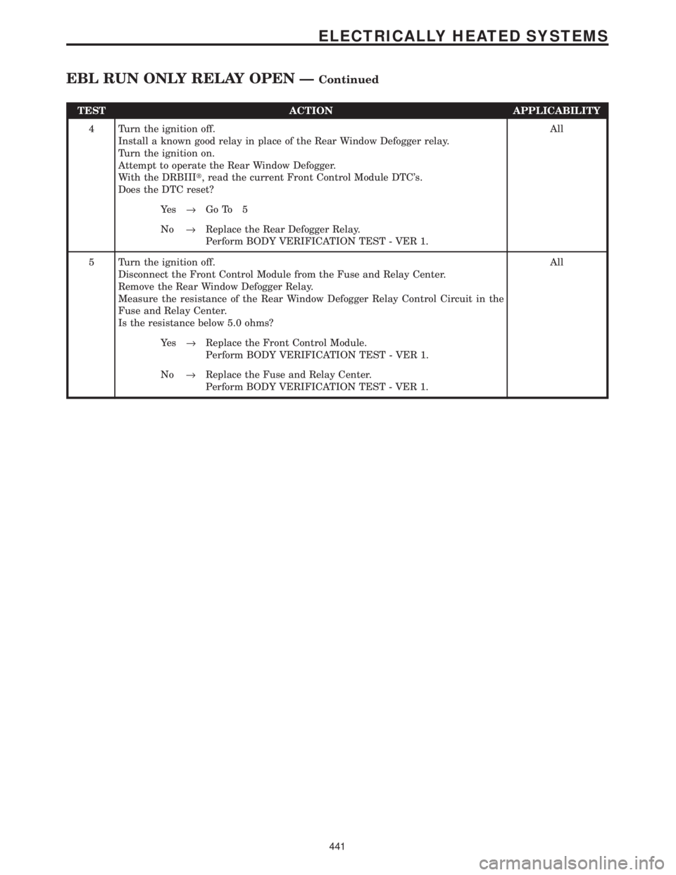
TEST ACTION APPLICABILITY
4 Turn the ignition off.
Install a known good relay in place of the Rear Window Defogger relay.
Turn the ignition on.
Attempt to operate the Rear Window Defogger.
With the DRBIIIt, read the current Front Control Module DTC's.
Does the DTC reset?All
Ye s®Go To 5
No®Replace the Rear Defogger Relay.
Perform BODY VERIFICATION TEST - VER 1.
5 Turn the ignition off.
Disconnect the Front Control Module from the Fuse and Relay Center.
Remove the Rear Window Defogger Relay.
Measure the resistance of the Rear Window Defogger Relay Control Circuit in the
Fuse and Relay Center.
Is the resistance below 5.0 ohms?All
Ye s®Replace the Front Control Module.
Perform BODY VERIFICATION TEST - VER 1.
No®Replace the Fuse and Relay Center.
Perform BODY VERIFICATION TEST - VER 1.
441
ELECTRICALLY HEATED SYSTEMS
EBL RUN ONLY RELAY OPEN ÐContinued