clutch CHRYSLER VOYAGER 2001 Service Manual
[x] Cancel search | Manufacturer: CHRYSLER, Model Year: 2001, Model line: VOYAGER, Model: CHRYSLER VOYAGER 2001Pages: 4284, PDF Size: 83.53 MB
Page 3967 of 4284
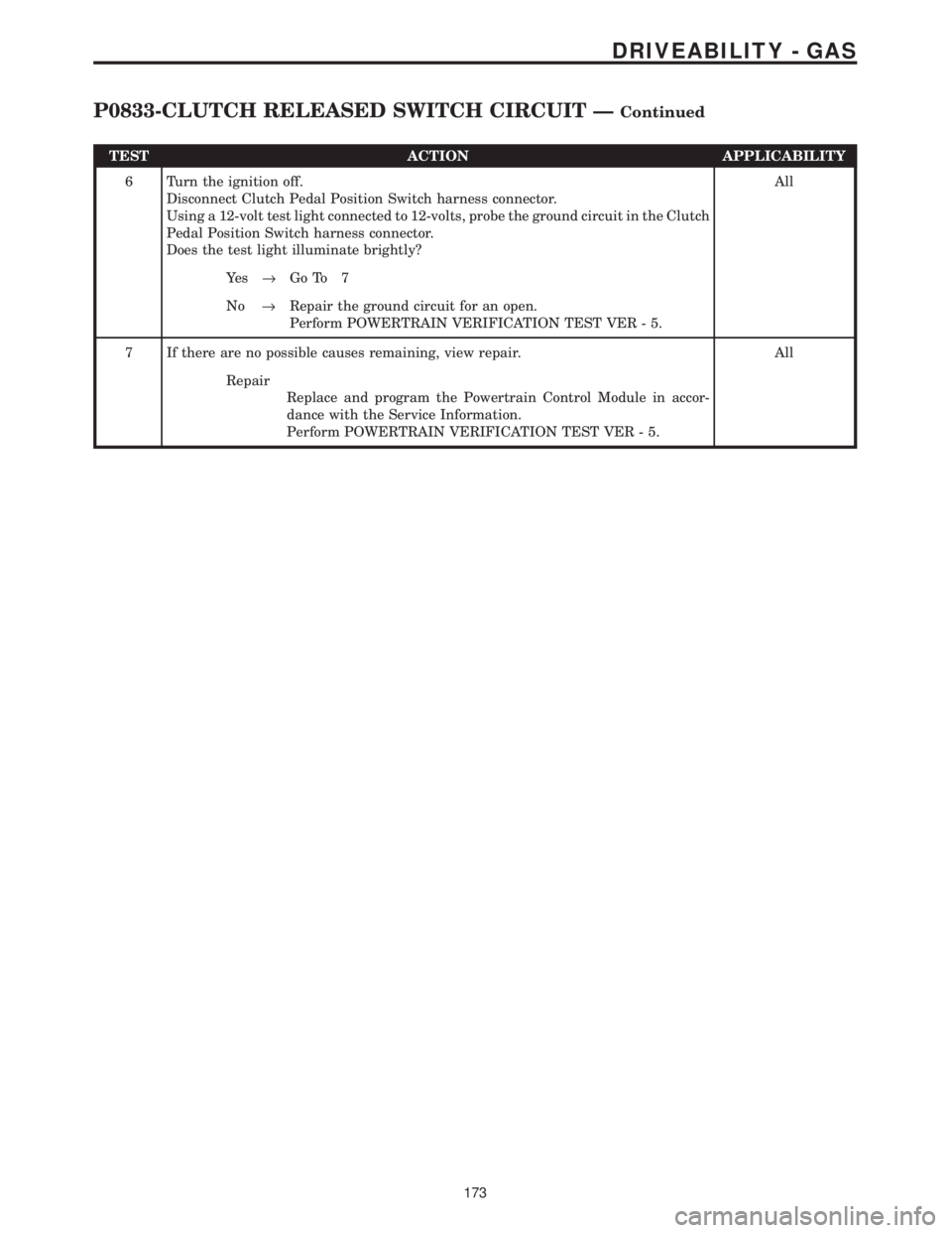
TEST ACTION APPLICABILITY
6 Turn the ignition off.
Disconnect Clutch Pedal Position Switch harness connector.
Using a 12-volt test light connected to 12-volts, probe the ground circuit in the Clutch
Pedal Position Switch harness connector.
Does the test light illuminate brightly?All
Ye s®Go To 7
No®Repair the ground circuit for an open.
Perform POWERTRAIN VERIFICATION TEST VER - 5.
7 If there are no possible causes remaining, view repair. All
Repair
Replace and program the Powertrain Control Module in accor-
dance with the Service Information.
Perform POWERTRAIN VERIFICATION TEST VER - 5.
173
DRIVEABILITY - GAS
P0833-CLUTCH RELEASED SWITCH CIRCUIT ÐContinued
Page 4030 of 4284
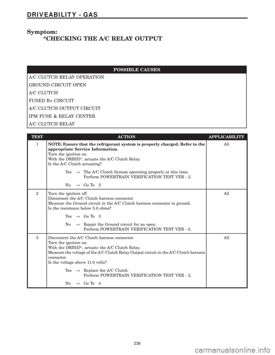
Symptom:
*CHECKING THE A/C RELAY OUTPUT
POSSIBLE CAUSES
A/C CLUTCH RELAY OPERATION
GROUND CIRCUIT OPEN
A/C CLUTCH
FUSED B+ CIRCUIT
A/C CLUTCH OUTPUT CIRCUIT
IPM FUSE & RELAY CENTER
A/C CLUTCH RELAY
TEST ACTION APPLICABILITY
1NOTE: Ensure that the refrigerant system is properly charged. Refer to the
appropriate Service Information.
Turn the ignition on.
With the DRBIIIt, actuate the A/C Clutch Relay.
Is the A/C Clutch actuating?All
Ye s®The A/C Clutch System operating properly at this time.
Perform POWERTRAIN VERIFICATION TEST VER - 2.
No®Go To 2
2 Turn the ignition off.
Disconnect the A/C Clutch harness connector.
Measure the Ground circuit in the A/C Clutch harness connector to ground.
Is the resistance below 5.0 ohms?All
Ye s®Go To 3
No®Repair the Ground circuit for an open.
Perform POWERTRAIN VERIFICATION TEST VER - 2.
3 Disconnect the A/C Clutch harness connector.
Turn the ignition on.
With the DRBIIIt, actuate the A/C Clutch Relay.
Measure the voltage of the A/C Clutch Relay Output circuit in the A/C Clutch harness
connector.
Is the voltage above 11.0 volts?All
Ye s®Replace the A/C Clutch.
Perform POWERTRAIN VERIFICATION TEST VER - 2.
No®Go To 4
236
DRIVEABILITY - GAS
Page 4031 of 4284
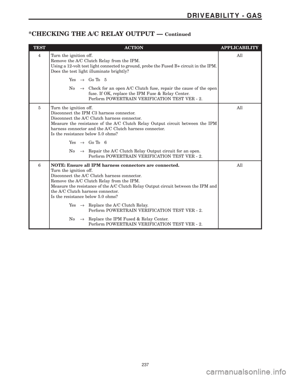
TEST ACTION APPLICABILITY
4 Turn the ignition off.
Remove the A/C Clutch Relay from the IPM.
Using a 12-volt test light connected to ground, probe the Fused B+ circuit in the IPM.
Does the test light illuminate brightly?All
Ye s®Go To 5
No®Check for an open A/C Clutch fuse, repair the cause of the open
fuse. If OK, replace the IPM Fuse & Relay Center.
Perform POWERTRAIN VERIFICATION TEST VER - 2.
5 Turn the ignition off.
Disconnect the IPM C3 harness connector.
Disconnect the A/C Clutch harness connector.
Measure the resistance of the A/C Clutch Relay Output circuit between the IPM
harness connector and the A/C Clutch harness connector.
Is the resistance below 5.0 ohms?All
Ye s®Go To 6
No®Repair the A/C Clutch Relay Output circuit for an open.
Perform POWERTRAIN VERIFICATION TEST VER - 2.
6NOTE: Ensure all IPM harness connectors are connected.
Turn the ignition off.
Disconnect the A/C Clutch harness connector.
Remove the A/C Clutch Relay from the IPM.
Measure the resistance of the A/C Clutch Relay Output circuit between the IPM and
the A/C Clutch harness connector.
Is the resistance below 5.0 ohms?All
Ye s®Replace the A/C Clutch Relay.
Perform POWERTRAIN VERIFICATION TEST VER - 2.
No®Replace the IPM Fused & Relay Center.
Perform POWERTRAIN VERIFICATION TEST VER - 2.
237
DRIVEABILITY - GAS
*CHECKING THE A/C RELAY OUTPUT ÐContinued
Page 4033 of 4284
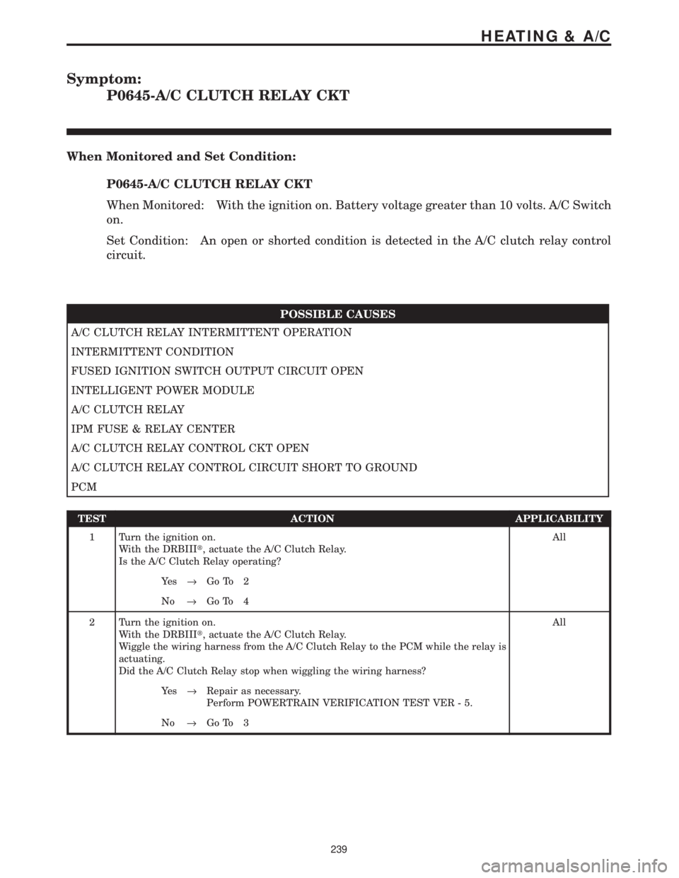
Symptom:
P0645-A/C CLUTCH RELAY CKT
When Monitored and Set Condition:
P0645-A/C CLUTCH RELAY CKT
When Monitored: With the ignition on. Battery voltage greater than 10 volts. A/C Switch
on.
Set Condition: An open or shorted condition is detected in the A/C clutch relay control
circuit.
POSSIBLE CAUSES
A/C CLUTCH RELAY INTERMITTENT OPERATION
INTERMITTENT CONDITION
FUSED IGNITION SWITCH OUTPUT CIRCUIT OPEN
INTELLIGENT POWER MODULE
A/C CLUTCH RELAY
IPM FUSE & RELAY CENTER
A/C CLUTCH RELAY CONTROL CKT OPEN
A/C CLUTCH RELAY CONTROL CIRCUIT SHORT TO GROUND
PCM
TEST ACTION APPLICABILITY
1 Turn the ignition on.
With the DRBIIIt, actuate the A/C Clutch Relay.
Is the A/C Clutch Relay operating?All
Ye s®Go To 2
No®Go To 4
2 Turn the ignition on.
With the DRBIIIt, actuate the A/C Clutch Relay.
Wiggle the wiring harness from the A/C Clutch Relay to the PCM while the relay is
actuating.
Did the A/C Clutch Relay stop when wiggling the wiring harness?All
Ye s®Repair as necessary.
Perform POWERTRAIN VERIFICATION TEST VER - 5.
No®Go To 3
239
HEATING & A/C
Page 4034 of 4284

TEST ACTION APPLICABILITY
3WARNING: KEEP CLEAR OF THE ENGINE'S MOVING PARTS.
NOTE: The conditions that set the DTC are not present at this time. The
following list may help in identifying the intermittent condition.
With the engine running at normal operating temperature, monitor the DRB
parameters related to the DTC while wiggling the wiring harness. Look for param-
eter values to change and/or a DTC to set.
Review the DRB Freeze Frame information. If possible, try to duplicate the
conditions under which the DTC was set.
Refer to any Technical Service Bulletins (TSB) that may apply.
Visually inspect the related wiring harness. Look for any chafed, pierced, pinched, or
partially broken wires.
Visually inspect the related wiring harness connectors. Look for broken, bent, pushed
out, or corroded terminals.
Were any of the above conditions present?All
Ye s®Repair as necessary
Perform POWERTRAIN VERIFICATION TEST VER - 5.
No®Test Complete.
4 Turn the ignition off.
Remove the A/C Clutch Relay from the IPM.
Turn the ignition on.
Using a 12-volt test light connected to ground, probe the Fused Ignition Switch
circuit in the IPM.
Does the test light illuminate?All
Ye s®Go To 5
No®Go To 10
5 Turn the ignition off.
Remove the A/C Clutch Relay from the IPM.
Turn the ignition on.
Using a 12-volt test light connected to 12-volts, probe the A/C Clutch Relay circuit in
the IPM.
With the DRBIIIt, actuate the A/C Clutch Relay.
Does the test light flash on and off?All
Ye s®Replace the A/C Clutch Relay.
Perform POWERTRAIN VERIFICATION TEST VER - 5.
No®Go To 6
6 Turn the ignition off.
Disconnect the Intelligent Power Module C3 harness connector.
Turn the ignition on.
Using a 12-volt test light connected to 12-volts, probe the A/C Clutch Relay Control
circuit in the IPM harness connector.
With the DRBIIIt, actuate the A/C Clutch Relay.
Does the test light flash on and off?All
Ye s®Replace the IPM Fused & Relay Center.
Perform POWERTRAIN VERIFICATION TEST VER - 5.
No®Go To 7
240
HEATING & A/C
P0645-A/C CLUTCH RELAY CKT ÐContinued
Page 4035 of 4284
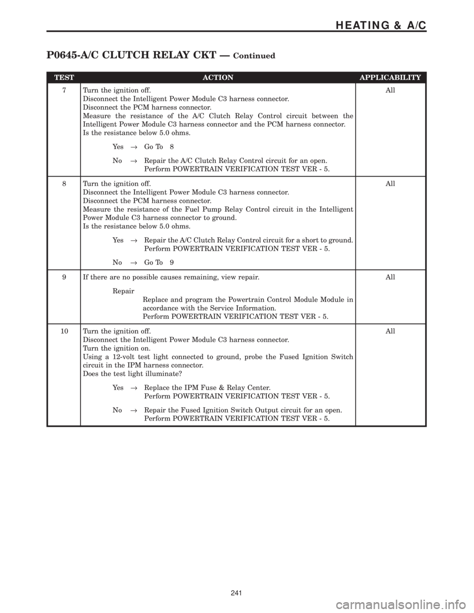
TEST ACTION APPLICABILITY
7 Turn the ignition off.
Disconnect the Intelligent Power Module C3 harness connector.
Disconnect the PCM harness connector.
Measure the resistance of the A/C Clutch Relay Control circuit between the
Intelligent Power Module C3 harness connector and the PCM harness connector.
Is the resistance below 5.0 ohms.All
Ye s®Go To 8
No®Repair the A/C Clutch Relay Control circuit for an open.
Perform POWERTRAIN VERIFICATION TEST VER - 5.
8 Turn the ignition off.
Disconnect the Intelligent Power Module C3 harness connector.
Disconnect the PCM harness connector.
Measure the resistance of the Fuel Pump Relay Control circuit in the Intelligent
Power Module C3 harness connector to ground.
Is the resistance below 5.0 ohms.All
Ye s®Repair the A/C Clutch Relay Control circuit for a short to ground.
Perform POWERTRAIN VERIFICATION TEST VER - 5.
No®Go To 9
9 If there are no possible causes remaining, view repair. All
Repair
Replace and program the Powertrain Control Module Module in
accordance with the Service Information.
Perform POWERTRAIN VERIFICATION TEST VER - 5.
10 Turn the ignition off.
Disconnect the Intelligent Power Module C3 harness connector.
Turn the ignition on.
Using a 12-volt test light connected to ground, probe the Fused Ignition Switch
circuit in the IPM harness connector.
Does the test light illuminate?All
Ye s®Replace the IPM Fuse & Relay Center.
Perform POWERTRAIN VERIFICATION TEST VER - 5.
No®Repair the Fused Ignition Switch Output circuit for an open.
Perform POWERTRAIN VERIFICATION TEST VER - 5.
241
HEATING & A/C
P0645-A/C CLUTCH RELAY CKT ÐContinued
Page 4085 of 4284
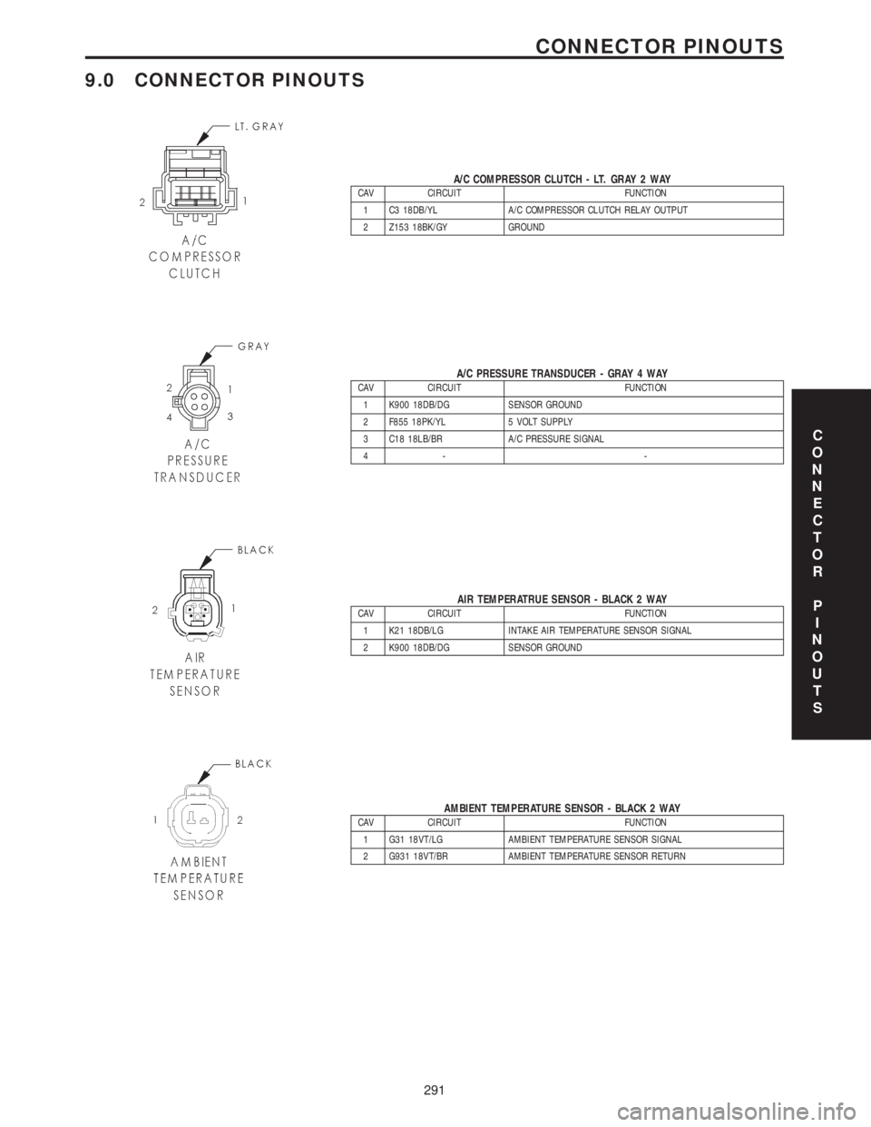
9.0 CONNECTOR PINOUTS
A/C COMPRESSOR CLUTCH - LT. GRAY 2 WAYCAV CIRCUIT FUNCTION
1 C3 18DB/YL A/C COMPRESSOR CLUTCH RELAY OUTPUT
2 Z153 18BK/GY GROUND
A/C PRESSURE TRANSDUCER - GRAY 4 WAYCAV CIRCUIT FUNCTION
1 K900 18DB/DG SENSOR GROUND
2 F855 18PK/YL 5 VOLT SUPPLY
3 C18 18LB/BR A/C PRESSURE SIGNAL
4- -
AIR TEMPERATRUE SENSOR - BLACK 2 WAYCAV CIRCUIT FUNCTION
1 K21 18DB/LG INTAKE AIR TEMPERATURE SENSOR SIGNAL
2 K900 18DB/DG SENSOR GROUND
AMBIENT TEMPERATURE SENSOR - BLACK 2 WAYCAV CIRCUIT FUNCTION
1 G31 18VT/LG AMBIENT TEMPERATURE SENSOR SIGNAL
2 G931 18VT/BR AMBIENT TEMPERATURE SENSOR RETURN
C
O
N
N
E
C
T
O
R
P
I
N
O
U
T
S
291
CONNECTOR PINOUTS
Page 4093 of 4284
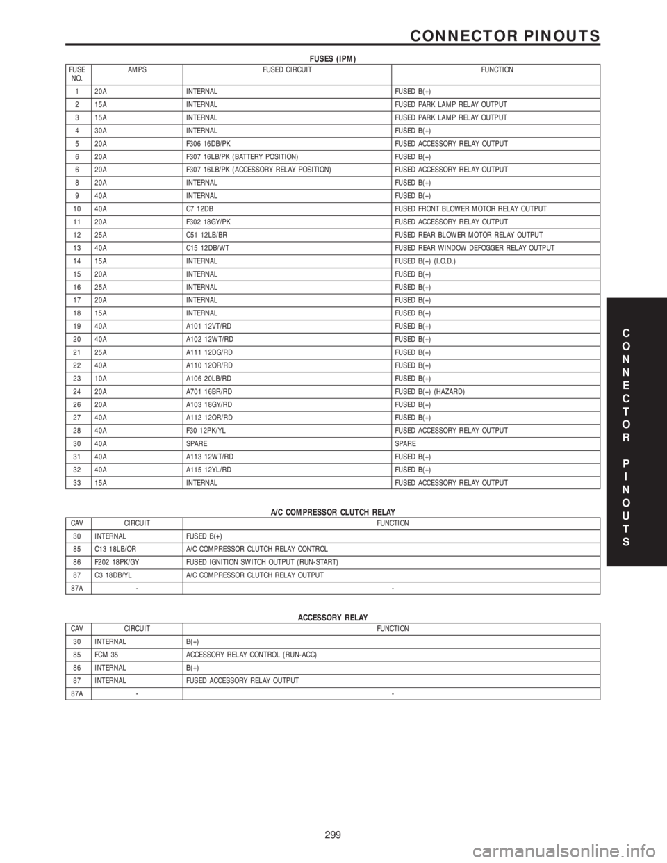
FUSES (IPM)FUSE
NO.AMPS FUSED CIRCUIT FUNCTION
1 20A INTERNAL FUSED B(+)
2 15A INTERNAL FUSED PARK LAMP RELAY OUTPUT
3 15A INTERNAL FUSED PARK LAMP RELAY OUTPUT
4 30A INTERNAL FUSED B(+)
5 20A F306 16DB/PK FUSED ACCESSORY RELAY OUTPUT
6 20A F307 16LB/PK (BATTERY POSITION) FUSED B(+)
6 20A F307 16LB/PK (ACCESSORY RELAY POSITION) FUSED ACCESSORY RELAY OUTPUT
8 20A INTERNAL FUSED B(+)
9 40A INTERNAL FUSED B(+)
10 40A C7 12DB FUSED FRONT BLOWER MOTOR RELAY OUTPUT
11 20A F302 18GY/PK FUSED ACCESSORY RELAY OUTPUT
12 25A C51 12LB/BR FUSED REAR BLOWER MOTOR RELAY OUTPUT
13 40A C15 12DB/WT FUSED REAR WINDOW DEFOGGER RELAY OUTPUT
14 15A INTERNAL FUSED B(+) (I.O.D.)
15 20A INTERNAL FUSED B(+)
16 25A INTERNAL FUSED B(+)
17 20A INTERNAL FUSED B(+)
18 15A INTERNAL FUSED B(+)
19 40A A101 12VT/RD FUSED B(+)
20 40A A102 12WT/RD FUSED B(+)
21 25A A111 12DG/RD FUSED B(+)
22 40A A110 12OR/RD FUSED B(+)
23 10A A106 20LB/RD FUSED B(+)
24 20A A701 16BR/RD FUSED B(+) (HAZARD)
26 20A A103 18GY/RD FUSED B(+)
27 40A A112 12OR/RD FUSED B(+)
28 40A F30 12PK/YL FUSED ACCESSORY RELAY OUTPUT
30 40A SPARE SPARE
31 40A A113 12WT/RD FUSED B(+)
32 40A A115 12YL/RD FUSED B(+)
33 15A INTERNAL FUSED ACCESSORY RELAY OUTPUT
A/C COMPRESSOR CLUTCH RELAYCAV CIRCUIT FUNCTION
30 INTERNAL FUSED B(+)
85 C13 18LB/OR A/C COMPRESSOR CLUTCH RELAY CONTROL
86 F202 18PK/GY FUSED IGNITION SWITCH OUTPUT (RUN-START)
87 C3 18DB/YL A/C COMPRESSOR CLUTCH RELAY OUTPUT
87A --
ACCESSORY RELAYCAV CIRCUIT FUNCTION
30 INTERNAL B(+)
85 FCM 35 ACCESSORY RELAY CONTROL (RUN-ACC)
86 INTERNAL B(+)
87 INTERNAL FUSED ACCESSORY RELAY OUTPUT
87A --
C
O
N
N
E
C
T
O
R
P
I
N
O
U
T
S
299
CONNECTOR PINOUTS
Page 4096 of 4284

POWERTRAIN CONTROL MODULE C2 - GRAY/GRAY 40 WAYCAV CIRCUIT FUNCTION
41 V37 18VT SPEED CONTROL SWITCH SIGNAL
42 C18 18LB/BR A/C PRESSURE SIGNAL
43 K900 18DB/DG SENSOR GROUND
44 F888 18BR/PK 8 VOLT SUPPLY
45 - -
46 A109 18OR/RD FUSED B(+)
47 - -
48 K40 18BR/LG (2.4L) IDLE AIR CONTROL NO. 3 DRIVER
49 K39 18VT/DG (3.3L/3.8L) IDLE AIR CONTROL NO. 1 DRIVER
49 K60 18VT/LG (2.4L) IDLE AIR CONTROL NO. 2 DRIVER
50 Z131 18BK/DG GROUND
51 K141 18DB/YL OXYGEN SENSOR 1/2 SIGNAL
52 - -
53 - -
54 - -
55 - -
56 V36 18VT/YL SPEED CONTROL VACUUM SOLENOID CONTROL
57 K39 18VT/DG (2.4L) IDLE AIR CONTROL NO. 1 DRIVER
57 K60 18VT/LG (3.3L/3.8L) IDLE AIR CONTROL NO. 2 DRIVER
58 K59 18BR/DG (2.4L) IDLE AIR CONTROL NO. 4 DRIVER
59 D25 18WT/VT PCI BUS
60 - -
61 F855 18PK/YL 5 VOLT SUPPLY
62 B29 18DG/WT BRAKE SWITCH SENSE
63 T10 18DG/LG (3.3L/3.8L) TORQUE MANAGEMENT REQUEST SENSE
64 C13 18LB/OR A/C COMPRESSOR CLUTCH RELAY CONTROL
65 D21 18WT/BR SCI TRANSMIT
66 N7 18DB/OR VEHICLE SPEED SENSOR OUTPUT
67 K51 18BR/WT AUTOMATIC SHUTDOWN RELAY CONTROL
68 K52 18DB/WT EVAPORATIVE EMISSION SOLENOID CONTROL
69 - -
70 K70 18DB/BR EVAPORATIVE EMISSION SOLENOID SENSE
71 - -
72 K107 18VT/WT LEAK DETECTION PUMP SWITCH SENSE
73 K173 18BR/VT RADIATOR FAN RELAY CONTROL
74 K31 18BR FUEL PUMP RELAY CONTROL
75 D20 18WT/LG SCI RECEIVE
76 T41 18YL/DB PARK/NEUTRAL POSITION SWITCH SENSE (TRS T41)
77 K106 18VT/LB LEAK DETECTION PUMP SOLENOID CONTROL
78 K54 18DB/WT (2.4L) TORQUE CONVERTER CLUTCH SOLENOID CONTROL
79 - -
80 V35 18VT/OR SPEED CONTROL VENT SOLENOID CONTROL
C
O
N
N
E
C
T
O
R
P
I
N
O
U
T
S
302
CONNECTOR PINOUTS
Page 4101 of 4284
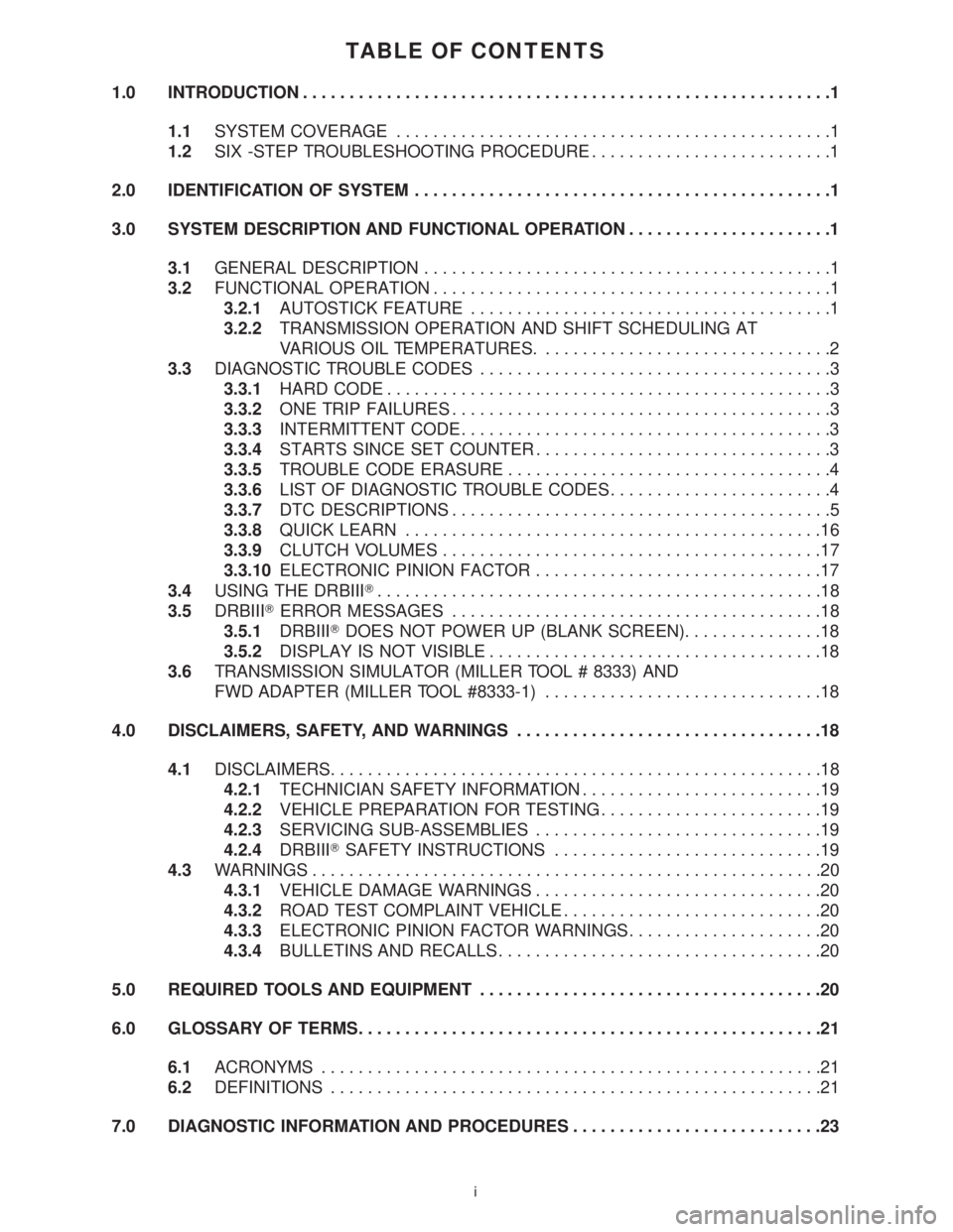
TABLE OF CONTENTS
1.0 INTRODUCTION.........................................................1
1.1SYSTEM COVERAGE...............................................1
1.2SIX -STEP TROUBLESHOOTING PROCEDURE..........................1
2.0 IDENTIFICATION OF SYSTEM.............................................1
3.0 SYSTEM DESCRIPTION AND FUNCTIONAL OPERATION......................1
3.1GENERAL DESCRIPTION............................................1
3.2FUNCTIONAL OPERATION...........................................1
3.2.1AUTOSTICK FEATURE.......................................1
3.2.2TRANSMISSION OPERATION AND SHIFT SCHEDULING AT
VARIOUS OIL TEMPERATURES................................2
3.3DIAGNOSTIC TROUBLE CODES......................................3
3.3.1HARD CODE................................................3
3.3.2ONE TRIP FAILURES.........................................3
3.3.3INTERMITTENT CODE........................................3
3.3.4STARTS SINCE SET COUNTER................................3
3.3.5TROUBLE CODE ERASURE...................................4
3.3.6LIST OF DIAGNOSTIC TROUBLE CODES........................4
3.3.7DTC DESCRIPTIONS.........................................5
3.3.8QUICK LEARN.............................................16
3.3.9CLUTCH VOLUMES.........................................17
3.3.10ELECTRONIC PINION FACTOR...............................17
3.4USING THE DRBIIIT................................................18
3.5DRBIIITERROR MESSAGES........................................18
3.5.1DRBIIITDOES NOT POWER UP (BLANK SCREEN)...............18
3.5.2DISPLAY IS NOT VISIBLE....................................18
3.6TRANSMISSION SIMULATOR (MILLER TOOL # 8333) AND
FWD ADAPTER (MILLER TOOL #8333-1)..............................18
4.0 DISCLAIMERS, SAFETY, AND WARNINGS.................................18
4.1DISCLAIMERS.....................................................18
4.2.1TECHNICIAN SAFETY INFORMATION..........................19
4.2.2VEHICLE PREPARATION FOR TESTING........................19
4.2.3SERVICING SUB-ASSEMBLIES...............................19
4.2.4DRBIIITSAFETY INSTRUCTIONS.............................19
4.3WARNINGS.......................................................20
4.3.1VEHICLE DAMAGE WARNINGS...............................20
4.3.2ROAD TEST COMPLAINT VEHICLE............................20
4.3.3ELECTRONIC PINION FACTOR WARNINGS.....................20
4.3.4BULLETINS AND RECALLS...................................20
5.0 REQUIRED TOOLS AND EQUIPMENT.....................................20
6.0 GLOSSARY OF TERMS..................................................21
6.1ACRONYMS......................................................21
6.2DEFINITIONS.....................................................21
7.0 DIAGNOSTIC INFORMATION AND PROCEDURES...........................23
i