clutch CHRYSLER VOYAGER 2001 Service Manual
[x] Cancel search | Manufacturer: CHRYSLER, Model Year: 2001, Model line: VOYAGER, Model: CHRYSLER VOYAGER 2001Pages: 4284, PDF Size: 83.53 MB
Page 3791 of 4284
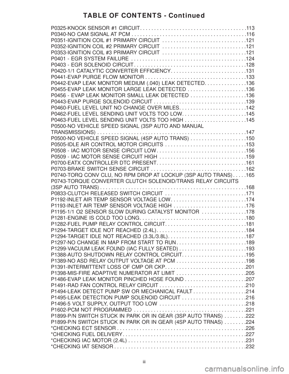
TABLE OF CONTENTS - Continued
P0325-KNOCK SENSOR #1 CIRCUIT......................................113
P0340-NO CAM SIGNAL AT PCM.........................................116
P0351-IGNITION COIL #1 PRIMARY CIRCUIT..............................121
P0352-IGNITION COIL #2 PRIMARY CIRCUIT..............................121
P0353-IGNITION COIL #3 PRIMARY CIRCUIT..............................121
P0401 - EGR SYSTEM FAILURE.........................................124
P0403 - EGR SOLENOID CIRCUIT........................................128
P0420-1/1 CATALYTIC CONVERTER EFFICIENCY...........................131
P0441-EVAP PURGE FLOW MONITOR....................................133
P0442-EVAP LEAK MONITOR MEDIUM (.040) LEAK DETECTED...............136
P0455-EVAP LEAK MONITOR LARGE LEAK DETECTED.....................136
P0456 - EVAP LEAK MONITOR SMALL LEAK DETECTED....................136
P0443-EVAP PURGE SOLENOID CIRCUIT.................................139
P0460-FUEL LEVEL UNIT NO CHANGE OVER MILES........................142
P0462-FUEL LEVEL SENDING UNIT VOLTS TOO LOW.......................145
P0463-FUEL LEVEL SENDING UNIT VOLTS TOO HIGH......................145
P0500-NO VEHICLE SPEED SIGNAL (3SP AUTO AND MANUAL
TRANSMISSIONS).....................................................147
P0500-NO VEHICLE SPEED SIGNAL (4SP AUTO TRANS)....................150
P0505-IDLE AIR CONTROL MOTOR CIRCUITS.............................153
P0508 - IAC MOTOR SENSE CIRCUIT LOW................................156
P0509 - IAC MOTOR SENSE CIRCUIT HIGH...............................159
P0700-EATX CONTROLLER DTC PRESENT................................161
P0703-BRAKE SWITCH SENSE CIRCUIT..................................162
P0740-TORQ CONV CLU, NO RPM DROP AT LOCKUP (3SP AUTO TRANS).....165
P0743-TORQUE CONVERTER CLUTCH SOLENOID/TRANS RELAY CIRCUITS
(3SP AUTO TRANS)....................................................168
P0833-CLUTCH RELEASED SWITCH CIRCUIT.............................171
P1192-INLET AIR TEMP SENSOR VOLTAGE LOW...........................174
P1193-INLET AIR TEMP SENSOR VOLTAGE HIGH..........................176
P1195-1/1 O2 SENSOR SLOW DURING CATALYST MONITOR................178
P1281-ENGINE IS COLD TOO LONG......................................180
P1282-FUEL PUMP RELAY CONTROL CIRCUIT.............................181
P1294-TARGET IDLE NOT REACHED (2.4L)................................184
P1294-TARGET IDLE NOT REACHED (3.3L/3.8L)............................187
P1297-NO CHANGE IN MAP FROM START TO RUN.........................189
P1299-VACUUM LEAK FOUND (IAC FULLY SEATED)........................193
P1388-AUTO SHUTDOWN RELAY CONTROL CIRCUIT.......................195
P1389-NO ASD RELAY OUTPUT VOLTAGE AT PCM.........................198
P1391-INTERMITTENT LOSS OF CMP OR CKP.............................201
P1398-MIS-FIRE ADAPTIVE NUMERATOR AT LIMIT.........................205
P1486-EVAP LEAK MONITOR PINCHED HOSE FOUND......................207
P1491-RAD FAN CONTROL RELAY CIRCUIT...............................210
P1494-LEAK DETECT PUMP SW OR MECHANICAL FAULT...................214
P1495-LEAK DETECTION PUMP SOLENOID CIRCUIT.......................216
P1496-5 VOLT SUPPLY, OUTPUT TOO LOW...............................218
P1602-PCM NOT PROGRAMMED........................................221
P1899-P/N SWITCH STUCK IN PARK OR IN GEAR (3SP AUTO TRANS)........222
P1899-P/N SWITCH STUCK IN PARK OR IN GEAR (4SP AUTO TRNAS)........224
*CHECKING ECT SENSOR..............................................226
*CHECKING FUEL DELIVERY............................................227
*CHECKING IAC MOTOR (2.4L)..........................................231
*CHECKING IAT SENSOR...............................................232
iii
Page 3792 of 4284

TABLE OF CONTENTS - Continued
*CHECKING MAP SENSOR..............................................233
*CHECKING PCM POWER AND GROUND CIRCUITS........................234
*CHECKING RADIATOR FAN RELAY OUTPUT..............................235
*CHECKING THE A/C RELAY OUTPUT....................................236
*CHECKING TP SENSOR...............................................238
HEATING & A/C
P0645-A/C CLUTCH RELAY CKT.........................................239
P1598-A/C PRESSURE SENSOR VOLTS TOO HIGH.........................242
P1599-A/C PRESSURE SENSOR VOLTS TOO LOW.........................245
SPEED CONTROL
P1595-SPEED CONTROL SOLENOID CIRCUITS............................248
P1683-SPD CTRL PWR RELAY; OR S/C 12V DRIVER CKT...................248
STARTING
*ENGINE CRANKS DOES NOT START....................................253
*NO CRANK CONDITION................................................258
*NO RESPONSE FROM PCM WITH A NO START CONDITION................261
*START AND STALL CONDITION.........................................262
VEHICLE THEFT/SECURITY
ANTENNA FAILURE....................................................266
COP FAILURE.........................................................266
EEPROM FAILURE.....................................................266
INTERNAL FAULT......................................................266
RAM FAILURE.........................................................266
SERIAL LINK INTERNAL FAULT..........................................266
STACK OVERFLOW FAILURE............................................266
PCM STATUS FAILURE.................................................268
SERIAL LINK EXTERNAL FAULT.........................................268
ROLLING CODE FAILURE...............................................270
TRANSPONDER COMMUNICATION FAILURE..............................272
TRANSPONDER CYCLIC REDUNDANCY CHECK (CRC) FAILURE.............272
TRANSPONDER ID MISMATCH..........................................272
TRANSPONDER RESPONSE MISMATCH..................................272
VERIFICATION TESTS
VERIFICATION TESTS..................................................275
8.0 COMPONENT LOCATIONS..............................................283
8.1CONTROL MODULES AND FUSE & RELAY CENTER...................283
8.2CONTROLS AND SOLENOID.......................................283
8.3DATA LINK CONNECTOR..........................................285
8.4SENSORS.......................................................286
8.5FUEL SYSTEM...................................................288
8.6SWITCHES......................................................289
9.0 CONNECTOR PINOUTS................................................291
A/C COMPRESSOR CLUTCH - LT. GRAY 2 WAY............................291
A/C PRESSURE TRANSDUCER - GRAY 4 WAY.............................291
AIR TEMPERATRUE SENSOR - BLACK 2 WAY.............................291
iv
Page 3793 of 4284
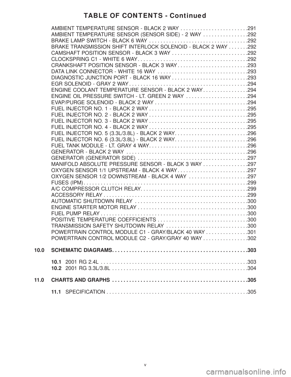
TABLE OF CONTENTS - Continued
AMBIENT TEMPERATURE SENSOR - BLACK 2 WAY........................291
AMBIENT TEMPERATURE SENSOR (SENSOR SIDE)-2WAY................292
BRAKE LAMP SWITCH - BLACK 6 WAY...................................292
BRAKE TRANSMISSION SHIFT INTERLOCK SOLENOID - BLACK 2 WAY.......292
CAMSHAFT POSITION SENSOR - BLACK 3 WAY...........................292
CLOCKSPRING C1 - WHITE 6 WAY.......................................292
CRANKSHAFT POSITION SENSOR - BLACK 3 WAY.........................293
DATA LINK CONNECTOR - WHITE 16 WAY................................293
DIAGNOSTIC JUNCTION PORT - BLACK 16 WAY...........................293
EGR SOLENOID - GRAY 2 WAY..........................................294
ENGINE COOLANT TEMPERATURE SENSOR - BLACK 2 WAY................294
ENGINE OIL PRESSURE SWITCH - LT. GREEN 2 WAY......................294
EVAP/PURGE SOLENOID - BLACK 2 WAY.................................294
FUEL INJECTOR NO. 1 - BLACK 2 WAY...................................295
FUEL INJECTOR NO. 2 - BLACK 2 WAY...................................295
FUEL INJECTOR NO. 3 - BLACK 2 WAY...................................295
FUEL INJECTOR NO. 4 - BLACK 2 WAY...................................295
FUEL INJECTOR NO. 5 (3.3L/3.8L) - BLACK 2 WAY..........................296
FUEL INJECTOR NO. 6 (3.3L/3.8L) - BLACK 2 WAY..........................296
FUEL TANK MODULE - LT. GRAY 4 WAY...................................296
GENERATOR - BLACK 2 WAY...........................................296
GENERATOR (GENERATOR SIDE).......................................297
MANIFOLD ABSOLUTE PRESSURE SENSOR - BLACK 3 WAY................297
OXYGEN SENSOR 1/1 UPSTREAM - BLACK 4 WAY.........................297
OXYGEN SENSOR 1/2 DOWNSTREAM - BLACK 4 WAY.....................297
FUSES (IPM)..........................................................299
A/C COMPRESSOR CLUTCH RELAY......................................299
ACCESSORY RELAY...................................................299
AUTOMATIC SHUTDOWN RELAY........................................300
ENGINE STARTER MOTOR RELAY.......................................300
FUEL PUMP RELAY....................................................300
POSITIVE TEMPERATURE COEFFICIENTS................................300
TRANSMISSION SAFETY SHUTDOWN RELAY.............................300
POWERTRAIN CONTROL MODULE C1 - GRAY/BLACK 40 WAY...............301
POWERTRAIN CONTROL MODULE C2 - GRAY/GRAY 40 WAY................302
10.0 SCHEMATIC DIAGRAMS................................................303
10.12001 RG 2.4L....................................................303
10.22001 RG 3.3L/3.8L................................................304
11.0 CHARTS AND GRAPHS................................................305
11.1SPECIFICATION..................................................305
v
Page 3799 of 4284
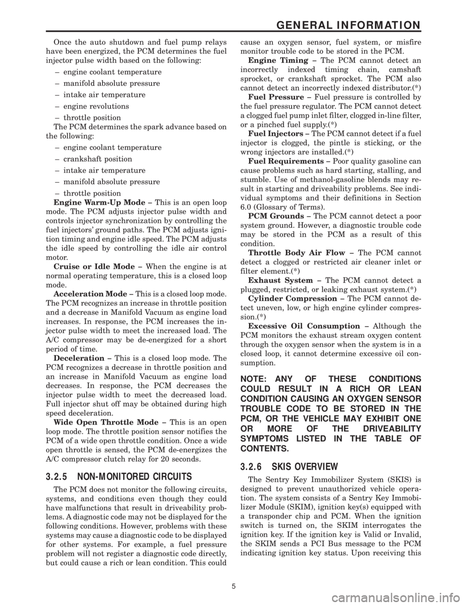
Once the auto shutdown and fuel pump relays
have been energized, the PCM determines the fuel
injector pulse width based on the following:
± engine coolant temperature
± manifold absolute pressure
± intake air temperature
± engine revolutions
± throttle position
The PCM determines the spark advance based on
the following:
± engine coolant temperature
± crankshaft position
± intake air temperature
± manifold absolute pressure
± throttle position
Engine Warm-Up Modeþ This is an open loop
mode. The PCM adjusts injector pulse width and
controls injector synchronization by controlling the
fuel injectors' ground paths. The PCM adjusts igni-
tion timing and engine idle speed. The PCM adjusts
the idle speed by controlling the idle air control
motor.
Cruise or Idle Modeþ When the engine is at
normal operating temperature, this is a closed loop
mode.
Acceleration Modeþ This is a closed loop mode.
The PCM recognizes an increase in throttle position
and a decrease in Manifold Vacuum as engine load
increases. In response, the PCM increases the in-
jector pulse width to meet the increased load. The
A/C compressor may be de-energized for a short
period of time.
Decelerationþ This is a closed loop mode. The
PCM recognizes a decrease in throttle position and
an increase in Manifold Vacuum as engine load
decreases. In response, the PCM decreases the
injector pulse width to meet the decreased load.
Full injector shut off may be obtained during high
speed deceleration.
Wide Open Throttle Modeþ This is an open
loop mode. The throttle position sensor notifies the
PCM of a wide open throttle condition. Once a wide
open throttle is sensed, the PCM de-energizes the
A/C compressor clutch relay for 20 seconds.
3.2.5 NON-MONITORED CIRCUITS
The PCM does not monitor the following circuits,
systems, and conditions even though they could
have malfunctions that result in driveability prob-
lems. A diagnostic code may not be displayed for the
following conditions. However, problems with these
systems may cause a diagnostic code to be displayed
for other systems. For example, a fuel pressure
problem will not register a diagnostic code directly,
but could cause a rich or lean condition. This couldcause an oxygen sensor, fuel system, or misfire
monitor trouble code to be stored in the PCM.
Engine Timingþ The PCM cannot detect an
incorrectly indexed timing chain, camshaft
sprocket, or crankshaft sprocket. The PCM also
cannot detect an incorrectly indexed distributor.(*)
Fuel Pressureþ Fuel pressure is controlled by
the fuel pressure regulator. The PCM cannot detect
a clogged fuel pump inlet filter, clogged in-line filter,
or a pinched fuel supply.(*)
Fuel Injectorsþ The PCM cannot detect if a fuel
injector is clogged, the pintle is sticking, or the
wrong injectors are installed.(*)
Fuel Requirementsþ Poor quality gasoline can
cause problems such as hard starting, stalling, and
stumble. Use of methanol-gasoline blends may re-
sult in starting and driveability problems. See indi-
vidual symptoms and their definitions in Section
6.0 (Glossary of Terms).
PCM Groundsþ The PCM cannot detect a poor
system ground. However, a diagnostic trouble code
may be stored in the PCM as a result of this
condition.
Throttle Body Air Flowþ The PCM cannot
detect a clogged or restricted air cleaner inlet or
filter element.(*)
Exhaust Systemþ The PCM cannot detect a
plugged, restricted, or leaking exhaust system.(*)
Cylinder Compressionþ The PCM cannot de-
tect uneven, low, or high engine cylinder compres-
sion.(*)
Excessive Oil Consumptionþ Although the
PCM monitors the exhaust stream oxygen content
through the oxygen sensor when the system is in a
closed loop, it cannot determine excessive oil con-
sumption.
NOTE: ANY OF THESE CONDITIONS
COULD RESULT IN A RICH OR LEAN
CONDITION CAUSING AN OXYGEN SENSOR
TROUBLE CODE TO BE STORED IN THE
PCM, OR THE VEHICLE MAY EXHIBIT ONE
OR MORE OF THE DRIVEABILITY
SYMPTOMS LISTED IN THE TABLE OF
CONTENTS.
3.2.6 SKIS OVERVIEW
The Sentry Key Immobilizer System (SKIS) is
designed to prevent unauthorized vehicle opera-
tion. The system consists of a Sentry Key Immobi-
lizer Module (SKIM), ignition key(s) equipped with
a transponder chip and PCM. When the ignition
switch is turned on, the SKIM interrogates the
ignition key. If the ignition key is Valid or Invalid,
the SKIM sends a PCI Bus message to the PCM
indicating ignition key status. Upon receiving this
5
GENERAL INFORMATION
Page 3960 of 4284
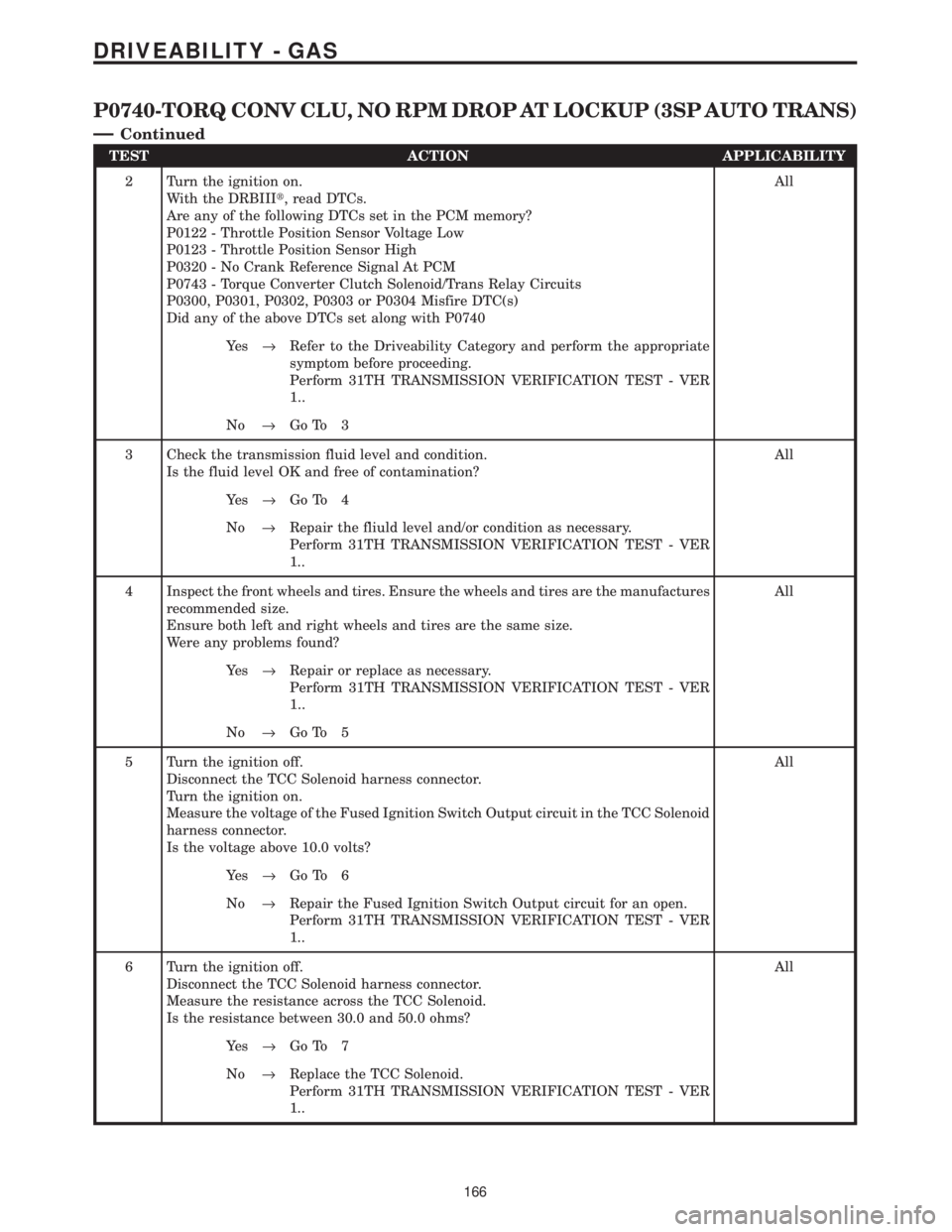
TEST ACTION APPLICABILITY
2 Turn the ignition on.
With the DRBIIIt, read DTCs.
Are any of the following DTCs set in the PCM memory?
P0122 - Throttle Position Sensor Voltage Low
P0123 - Throttle Position Sensor High
P0320 - No Crank Reference Signal At PCM
P0743 - Torque Converter Clutch Solenoid/Trans Relay Circuits
P0300, P0301, P0302, P0303 or P0304 Misfire DTC(s)
Did any of the above DTCs set along with P0740All
Ye s®Refer to the Driveability Category and perform the appropriate
symptom before proceeding.
Perform 31TH TRANSMISSION VERIFICATION TEST - VER
1..
No®Go To 3
3 Check the transmission fluid level and condition.
Is the fluid level OK and free of contamination?All
Ye s®Go To 4
No®Repair the fliuld level and/or condition as necessary.
Perform 31TH TRANSMISSION VERIFICATION TEST - VER
1..
4 Inspect the front wheels and tires. Ensure the wheels and tires are the manufactures
recommended size.
Ensure both left and right wheels and tires are the same size.
Were any problems found?All
Ye s®Repair or replace as necessary.
Perform 31TH TRANSMISSION VERIFICATION TEST - VER
1..
No®Go To 5
5 Turn the ignition off.
Disconnect the TCC Solenoid harness connector.
Turn the ignition on.
Measure the voltage of the Fused Ignition Switch Output circuit in the TCC Solenoid
harness connector.
Is the voltage above 10.0 volts?All
Ye s®Go To 6
No®Repair the Fused Ignition Switch Output circuit for an open.
Perform 31TH TRANSMISSION VERIFICATION TEST - VER
1..
6 Turn the ignition off.
Disconnect the TCC Solenoid harness connector.
Measure the resistance across the TCC Solenoid.
Is the resistance between 30.0 and 50.0 ohms?All
Ye s®Go To 7
No®Replace the TCC Solenoid.
Perform 31TH TRANSMISSION VERIFICATION TEST - VER
1..
166
DRIVEABILITY - GAS
P0740-TORQ CONV CLU, NO RPM DROP AT LOCKUP (3SP AUTO TRANS)
Ð
Continued
Page 3962 of 4284
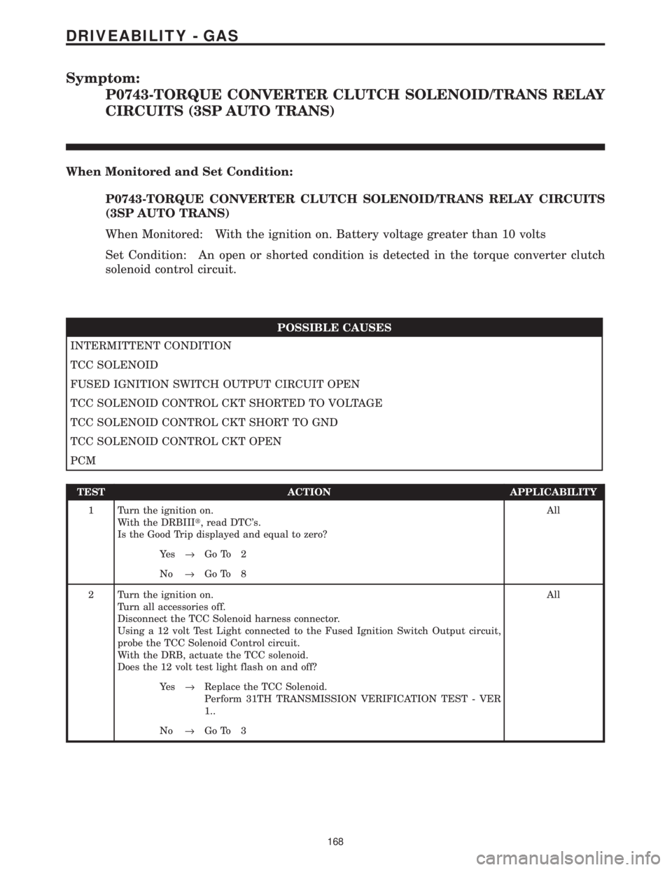
Symptom:
P0743-TORQUE CONVERTER CLUTCH SOLENOID/TRANS RELAY
CIRCUITS (3SP AUTO TRANS)
When Monitored and Set Condition:
P0743-TORQUE CONVERTER CLUTCH SOLENOID/TRANS RELAY CIRCUITS
(3SP AUTO TRANS)
When Monitored: With the ignition on. Battery voltage greater than 10 volts
Set Condition: An open or shorted condition is detected in the torque converter clutch
solenoid control circuit.
POSSIBLE CAUSES
INTERMITTENT CONDITION
TCC SOLENOID
FUSED IGNITION SWITCH OUTPUT CIRCUIT OPEN
TCC SOLENOID CONTROL CKT SHORTED TO VOLTAGE
TCC SOLENOID CONTROL CKT SHORT TO GND
TCC SOLENOID CONTROL CKT OPEN
PCM
TEST ACTION APPLICABILITY
1 Turn the ignition on.
With the DRBIIIt, read DTC's.
Is the Good Trip displayed and equal to zero?All
Ye s®Go To 2
No®Go To 8
2 Turn the ignition on.
Turn all accessories off.
Disconnect the TCC Solenoid harness connector.
Using a 12 volt Test Light connected to the Fused Ignition Switch Output circuit,
probe the TCC Solenoid Control circuit.
With the DRB, actuate the TCC solenoid.
Does the 12 volt test light flash on and off?All
Ye s®Replace the TCC Solenoid.
Perform 31TH TRANSMISSION VERIFICATION TEST - VER
1..
No®Go To 3
168
DRIVEABILITY - GAS
Page 3963 of 4284
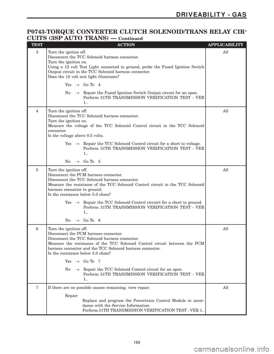
TEST ACTION APPLICABILITY
3 Turn the igntion off.
Disconnect the TCC Solenoid harness connector.
Turn the ignition on.
Using a 12 volt Test Light connected to ground, probe the Fused Ignition Switch
Output circuit in the TCC Solenoid harness connector.
Does the 12 volt test light illuminate?All
Ye s®Go To 4
No®Repair the Fused Ignition Switch Output circuit for an open.
Perform 31TH TRANSMISSION VERIFICATION TEST - VER
1..
4 Turn the ignition off.
Disconnect the TCC Solenoid harness connector.
Turn the ignition on.
Measure the voltage of the TCC Solenoid Control circuit in the TCC Solenoid
connector.
Is the voltage above 0.5 volts.All
Ye s®Repair the TCC Solenoid Control circuit for a short to voltage.
Perform 31TH TRANSMISSION VERIFICATION TEST - VER
1..
No®Go To 5
5 Turn the ignition off.
Disconnect the PCM harness connector.
Disconnect the TCC Solenoid harness connector.
Measure the resistance of the TCC Solenoid Control circuit in the TCC Solenoid
harness connector to ground.
Is the resistance below 5.0 ohms?All
Ye s®Repair the TCC Solenoid Control circuirt for a short to ground.
Perform 31TH TRANSMISSION VERIFICATION TEST - VER
1..
No®Go To 6
6 Turn the ignition off.
Disconnect the PCM harness connector.
Disconnect the TCC Solenoid harness connector.
Measure the resistance of the TCC Solenoid Control circuit between the PCM
harness connector and the TCC Solenoid harness connector.
Is the resistance below 5.0 ohms?All
Ye s®Go To 7
No®Repair the TCC Solenoid Control circuit for an open.
Perform 31TH TRANSMISSION VERIFICATION TEST - VER
1..
7 If there are no possible causes remaining, view repair. All
Repair
Replace and program the Powertrain Control Module in accor-
dance with the Service Information.
Perform 31TH TRANSMISSION VERIFICATION TEST - VER 1..
169
DRIVEABILITY - GAS
P0743-TORQUE CONVERTER CLUTCH SOLENOID/TRANS RELAY CIR-
CUITS (3SP AUTO TRANS) Ð
Continued
Page 3964 of 4284
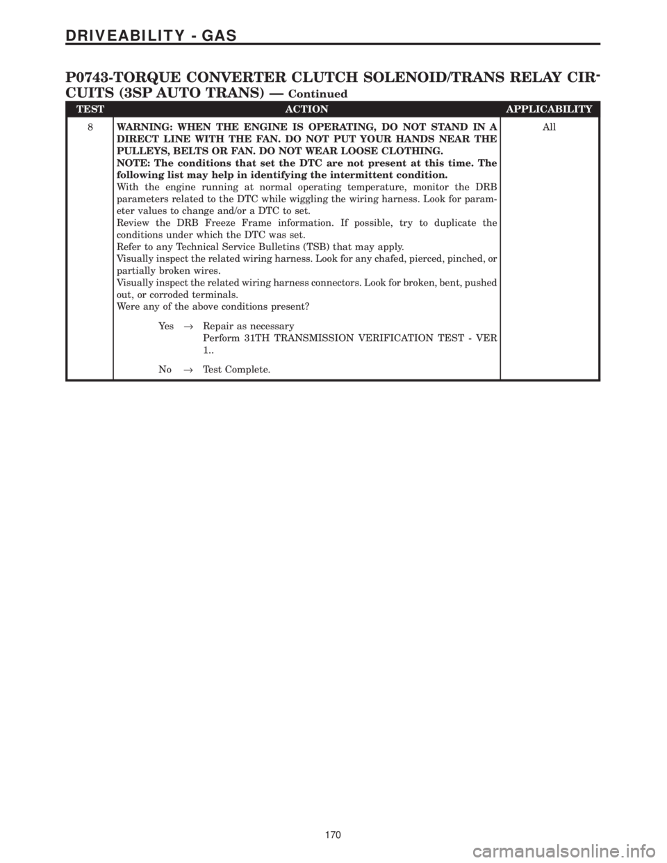
TEST ACTION APPLICABILITY
8WARNING: WHEN THE ENGINE IS OPERATING, DO NOT STAND IN A
DIRECT LINE WITH THE FAN. DO NOT PUT YOUR HANDS NEAR THE
PULLEYS, BELTS OR FAN. DO NOT WEAR LOOSE CLOTHING.
NOTE: The conditions that set the DTC are not present at this time. The
following list may help in identifying the intermittent condition.
With the engine running at normal operating temperature, monitor the DRB
parameters related to the DTC while wiggling the wiring harness. Look for param-
eter values to change and/or a DTC to set.
Review the DRB Freeze Frame information. If possible, try to duplicate the
conditions under which the DTC was set.
Refer to any Technical Service Bulletins (TSB) that may apply.
Visually inspect the related wiring harness. Look for any chafed, pierced, pinched, or
partially broken wires.
Visually inspect the related wiring harness connectors. Look for broken, bent, pushed
out, or corroded terminals.
Were any of the above conditions present?All
Ye s®Repair as necessary
Perform 31TH TRANSMISSION VERIFICATION TEST - VER
1..
No®Test Complete.
170
DRIVEABILITY - GAS
P0743-TORQUE CONVERTER CLUTCH SOLENOID/TRANS RELAY CIR-
CUITS (3SP AUTO TRANS) Ð
Continued
Page 3965 of 4284
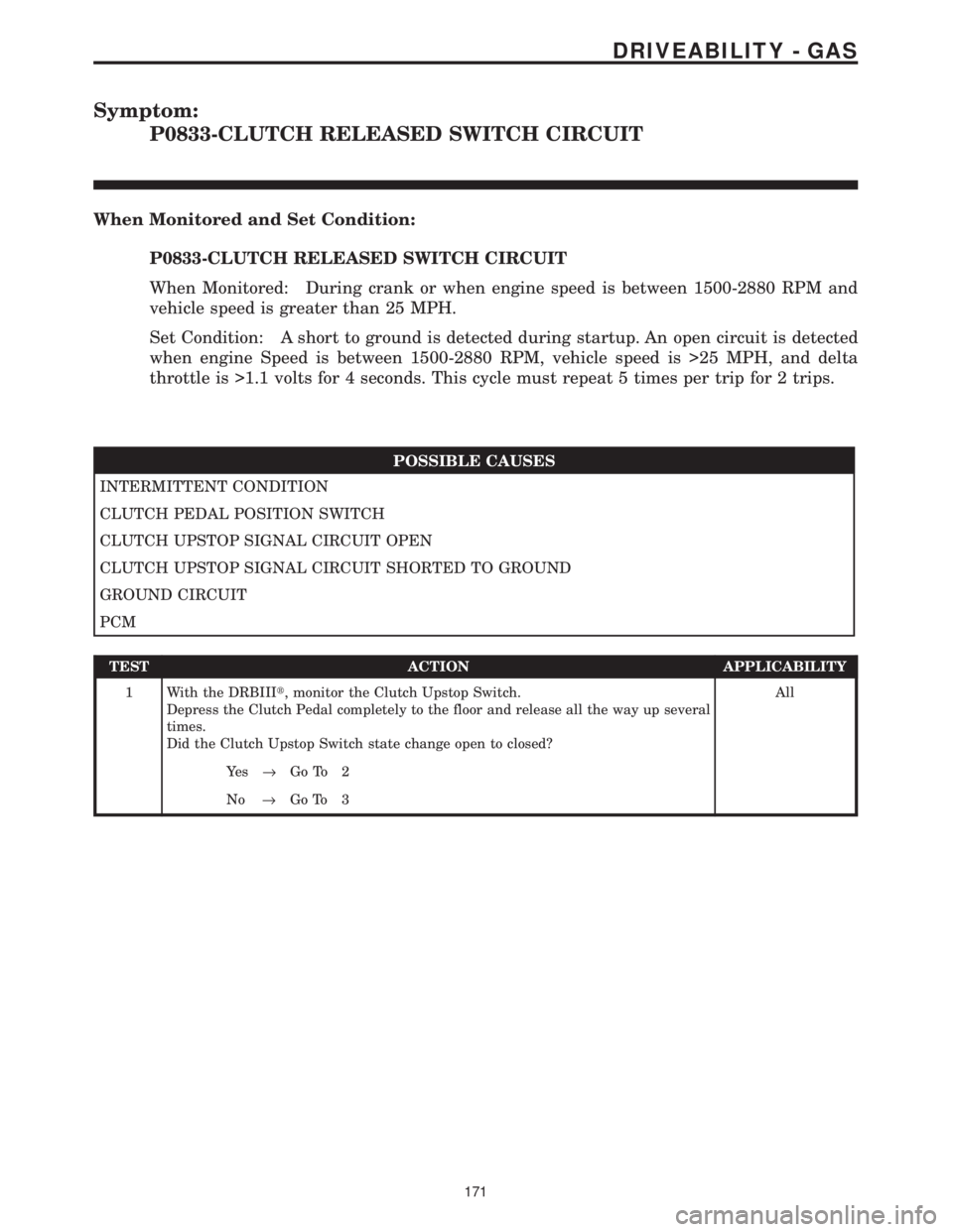
Symptom:
P0833-CLUTCH RELEASED SWITCH CIRCUIT
When Monitored and Set Condition:
P0833-CLUTCH RELEASED SWITCH CIRCUIT
When Monitored: During crank or when engine speed is between 1500-2880 RPM and
vehicle speed is greater than 25 MPH.
Set Condition: A short to ground is detected during startup. An open circuit is detected
when engine Speed is between 1500-2880 RPM, vehicle speed is >25 MPH, and delta
throttle is >1.1 volts for 4 seconds. This cycle must repeat 5 times per trip for 2 trips.
POSSIBLE CAUSES
INTERMITTENT CONDITION
CLUTCH PEDAL POSITION SWITCH
CLUTCH UPSTOP SIGNAL CIRCUIT OPEN
CLUTCH UPSTOP SIGNAL CIRCUIT SHORTED TO GROUND
GROUND CIRCUIT
PCM
TEST ACTION APPLICABILITY
1 With the DRBIIIt, monitor the Clutch Upstop Switch.
Depress the Clutch Pedal completely to the floor and release all the way up several
times.
Did the Clutch Upstop Switch state change open to closed?All
Ye s®Go To 2
No®Go To 3
171
DRIVEABILITY - GAS
Page 3966 of 4284
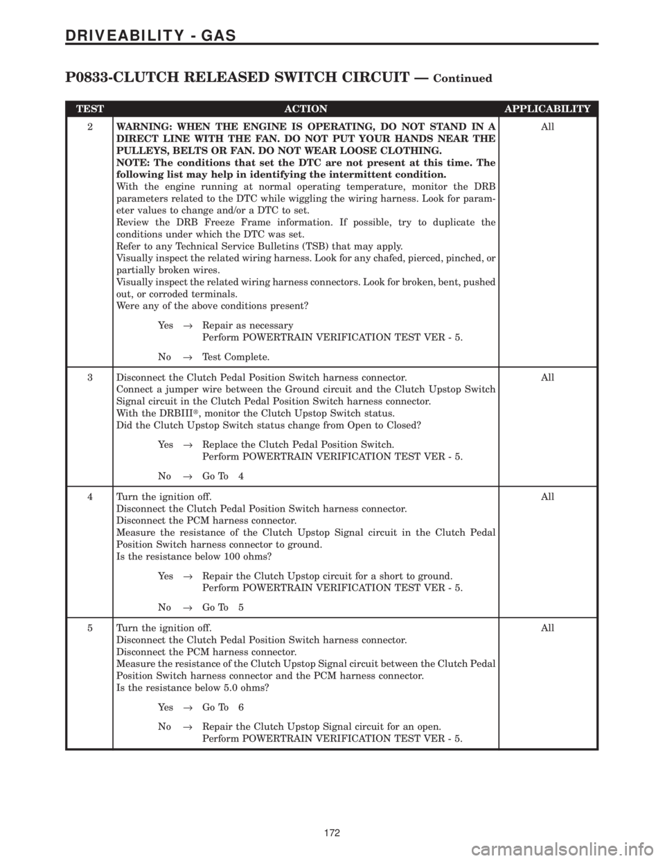
TEST ACTION APPLICABILITY
2WARNING: WHEN THE ENGINE IS OPERATING, DO NOT STAND IN A
DIRECT LINE WITH THE FAN. DO NOT PUT YOUR HANDS NEAR THE
PULLEYS, BELTS OR FAN. DO NOT WEAR LOOSE CLOTHING.
NOTE: The conditions that set the DTC are not present at this time. The
following list may help in identifying the intermittent condition.
With the engine running at normal operating temperature, monitor the DRB
parameters related to the DTC while wiggling the wiring harness. Look for param-
eter values to change and/or a DTC to set.
Review the DRB Freeze Frame information. If possible, try to duplicate the
conditions under which the DTC was set.
Refer to any Technical Service Bulletins (TSB) that may apply.
Visually inspect the related wiring harness. Look for any chafed, pierced, pinched, or
partially broken wires.
Visually inspect the related wiring harness connectors. Look for broken, bent, pushed
out, or corroded terminals.
Were any of the above conditions present?All
Ye s®Repair as necessary
Perform POWERTRAIN VERIFICATION TEST VER - 5.
No®Test Complete.
3 Disconnect the Clutch Pedal Position Switch harness connector.
Connect a jumper wire between the Ground circuit and the Clutch Upstop Switch
Signal circuit in the Clutch Pedal Position Switch harness connector.
With the DRBIIIt, monitor the Clutch Upstop Switch status.
Did the Clutch Upstop Switch status change from Open to Closed?All
Ye s®Replace the Clutch Pedal Position Switch.
Perform POWERTRAIN VERIFICATION TEST VER - 5.
No®Go To 4
4 Turn the ignition off.
Disconnect the Clutch Pedal Position Switch harness connector.
Disconnect the PCM harness connector.
Measure the resistance of the Clutch Upstop Signal circuit in the Clutch Pedal
Position Switch harness connector to ground.
Is the resistance below 100 ohms?All
Ye s®Repair the Clutch Upstop circuit for a short to ground.
Perform POWERTRAIN VERIFICATION TEST VER - 5.
No®Go To 5
5 Turn the ignition off.
Disconnect the Clutch Pedal Position Switch harness connector.
Disconnect the PCM harness connector.
Measure the resistance of the Clutch Upstop Signal circuit between the Clutch Pedal
Position Switch harness connector and the PCM harness connector.
Is the resistance below 5.0 ohms?All
Ye s®Go To 6
No®Repair the Clutch Upstop Signal circuit for an open.
Perform POWERTRAIN VERIFICATION TEST VER - 5.
172
DRIVEABILITY - GAS
P0833-CLUTCH RELEASED SWITCH CIRCUIT ÐContinued