CHRYSLER VOYAGER 2001 Service Manual
Manufacturer: CHRYSLER, Model Year: 2001, Model line: VOYAGER, Model: CHRYSLER VOYAGER 2001Pages: 4284, PDF Size: 83.53 MB
Page 3621 of 4284
PLASTIC GROCERY BAG
RETAINER
REMOVAL
3-PASS BENCH SEAT
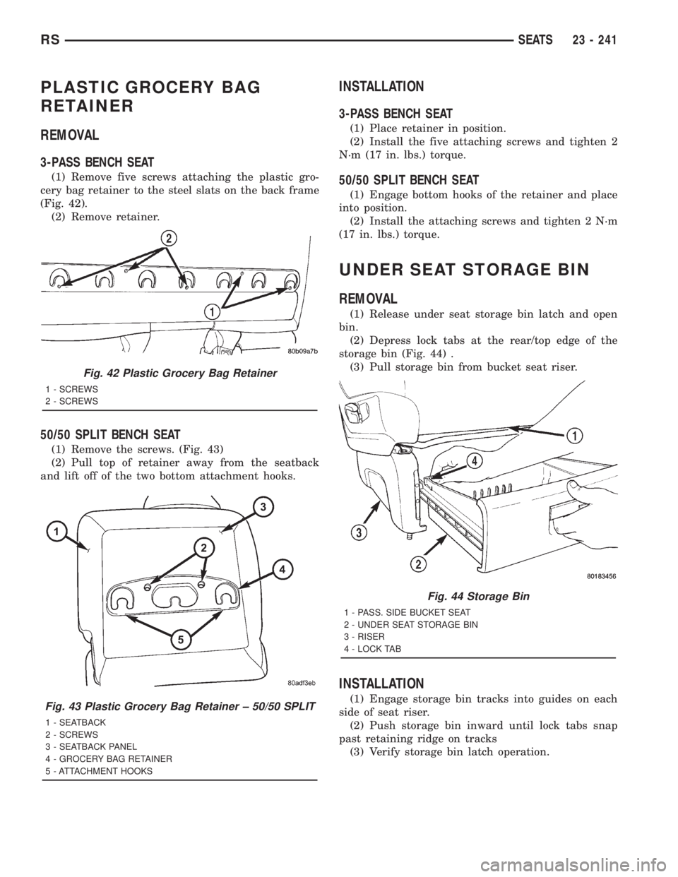
(1) Remove five screws attaching the plastic gro-
cery bag retainer to the steel slats on the back frame
(Fig. 42).
(2) Remove retainer.
50/50 SPLIT BENCH SEAT
(1) Remove the screws. (Fig. 43)
(2) Pull top of retainer away from the seatback
and lift off of the two bottom attachment hooks.
INSTALLATION
3-PASS BENCH SEAT
(1) Place retainer in position.
(2) Install the five attaching screws and tighten 2
N´m (17 in. lbs.) torque.
50/50 SPLIT BENCH SEAT
(1) Engage bottom hooks of the retainer and place
into position.
(2) Install the attaching screws and tighten 2 N´m
(17 in. lbs.) torque.
UNDER SEAT STORAGE BIN
REMOVAL
(1) Release under seat storage bin latch and open
bin.
(2) Depress lock tabs at the rear/top edge of the
storage bin (Fig. 44) .
(3) Pull storage bin from bucket seat riser.
INSTALLATION
(1) Engage storage bin tracks into guides on each
side of seat riser.
(2) Push storage bin inward until lock tabs snap
past retaining ridge on tracks
(3) Verify storage bin latch operation.
Fig. 42 Plastic Grocery Bag Retainer
1 - SCREWS
2 - SCREWS
Fig. 43 Plastic Grocery Bag Retainer ± 50/50 SPLIT
1 - SEATBACK
2 - SCREWS
3 - SEATBACK PANEL
4 - GROCERY BAG RETAINER
5 - ATTACHMENT HOOKS
Fig. 44 Storage Bin
1 - PASS. SIDE BUCKET SEAT
2 - UNDER SEAT STORAGE BIN
3 - RISER
4 - LOCK TAB
RSSEATS23 - 241
Page 3622 of 4284
UNDER SEAT STORAGE BIN
GUIDE
REMOVAL
(1) Remove under seat storage bin. (Refer to 23 -
BODY/SEATS/UNDER SEAT STORAGE BIN -
REMOVAL).
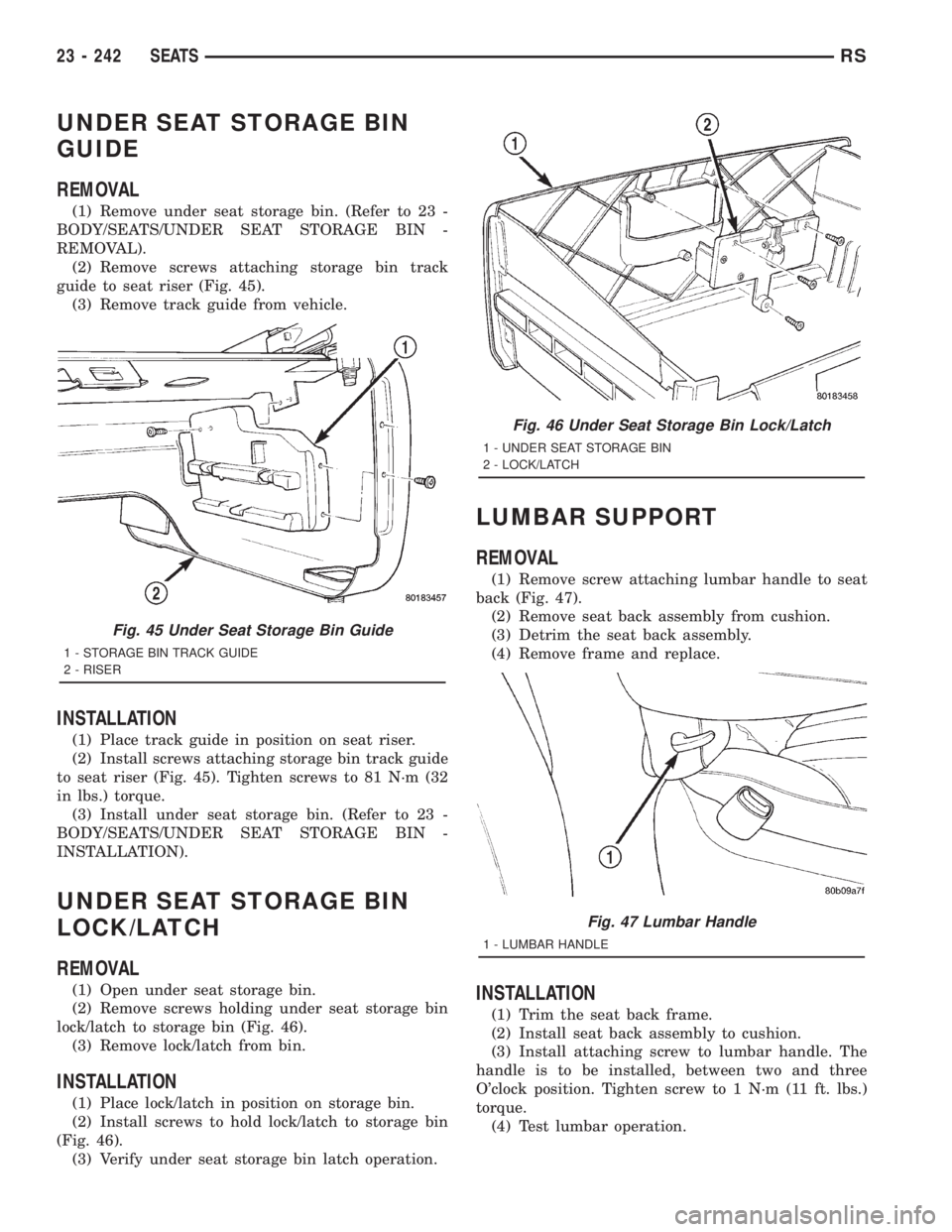
(2) Remove screws attaching storage bin track
guide to seat riser (Fig. 45).
(3) Remove track guide from vehicle.
INSTALLATION
(1) Place track guide in position on seat riser.
(2) Install screws attaching storage bin track guide
to seat riser (Fig. 45). Tighten screws to 81 N´m (32
in lbs.) torque.
(3) Install under seat storage bin. (Refer to 23 -
BODY/SEATS/UNDER SEAT STORAGE BIN -
INSTALLATION).
UNDER SEAT STORAGE BIN
LOCK/LATCH
REMOVAL
(1) Open under seat storage bin.
(2) Remove screws holding under seat storage bin
lock/latch to storage bin (Fig. 46).
(3) Remove lock/latch from bin.
INSTALLATION
(1) Place lock/latch in position on storage bin.
(2) Install screws to hold lock/latch to storage bin
(Fig. 46).
(3) Verify under seat storage bin latch operation.
LUMBAR SUPPORT
REMOVAL
(1) Remove screw attaching lumbar handle to seat
back (Fig. 47).
(2) Remove seat back assembly from cushion.
(3) Detrim the seat back assembly.
(4) Remove frame and replace.
INSTALLATION
(1) Trim the seat back frame.
(2) Install seat back assembly to cushion.
(3) Install attaching screw to lumbar handle. The
handle is to be installed, between two and three
O'clock position. Tighten screw to 1 N´m (11 ft. lbs.)
torque.
(4) Test lumbar operation.
Fig. 45 Under Seat Storage Bin Guide
1 - STORAGE BIN TRACK GUIDE
2 - RISER
Fig. 46 Under Seat Storage Bin Lock/Latch
1 - UNDER SEAT STORAGE BIN
2 - LOCK/LATCH
Fig. 47 Lumbar Handle
1 - LUMBAR HANDLE
23 - 242 SEATSRS
Page 3623 of 4284
STATIONARY GLASS
TABLE OF CONTENTS
page page
WINDSHIELD
DESCRIPTION..........................243
WARNING.............................243
REMOVAL.............................243
INSTALLATION..........................244
SLIDING DOOR GLASS
REMOVAL.............................245INSTALLATION..........................245
QUARTER WINDOW
REMOVAL.............................246
INSTALLATION..........................246
REAR DOOR GLASS
REMOVAL.............................246
INSTALLATION..........................246
WINDSHIELD
DESCRIPTION
The windshield is attached to the window frame
with urethane adhesive. The urethane adhesive is
applied cold and seals the surface area between the
window opening and the glass. The primer adheres
the urethane adhesive to the windshield.
It is difficult to salvage a windshield during the
removal operation. The windshield is part of the
structural support for the roof. The urethane bonding
used to secure the windshield to the fence is difficult
to cut or clean from any surface. If the moldings are
set in urethane, it would also be unlikely they could
be salvaged. Before removing the windshield, check
the availability of the windshield and moldings from
the parts supplier.
WINDSHIELD SAFETY PRECAUTIONS
WARNING: DO NOT OPERATE THE VEHICLE
WITHIN 24 HOURS OF WINDSHIELD INSTALLATION.
IT TAKES AT LEAST 24 HOURS FOR URETHANE
ADHESIVE TO CURE. IF IT IS NOT CURED, THE
WINDSHIELD MAY NOT PERFORM PROPERLY IN
AN ACCIDENT.
URETHANE ADHESIVES ARE APPLIED AS A SYS-
TEM. USE GLASS CLEANER, GLASS PREP SOL-
VENT, GLASS PRIMER, PVC (VINYL) PRIMER AND
PINCH WELD (FENCE) PRIMER PROVIDED BY THE
ADHESIVE MANUFACTURER. IF NOT, STRUCTURAL
INTEGRITY COULD BE COMPROMISED.
DAIMLERCHRYSLER DOES NOT RECOMMEND
GLASS ADHESIVE BY BRAND. TECHNICIANS
SHOULD REVIEW PRODUCT LABELS AND TECHNI-
CAL DATA SHEETS, AND USE ONLY ADHESIVES
THAT THEIR MANUFACTURES WARRANT WILL
RESTORE A VEHICLE TO THE REQUIREMENTS OF
FMVSS 212. TECHNICIANS SHOULD ALSO INSURE
THAT PRIMERS AND CLEANERS ARE COMPATIBLEWITH THE PARTICULAR ADHESIVE USED.
BE SURE TO REFER TO THE URETHANE MANU-
FACTURER'S DIRECTIONS FOR CURING TIME
SPECIFICATIONS, AND DO NOT USE ADHESIVE
AFTER ITS EXPIRATION DATE.
VAPORS THAT ARE EMITTED FROM THE URE-
THANE ADHESIVE OR PRIMER COULD CAUSE
PERSONAL INJURY. USE THEM IN A WELL-VENTI-
LATED AREA.
SKIN CONTACT WITH URETHANE ADHESIVE
SHOULD BE AVOIDED. PERSONAL INJURY MAY
RESULT.
ALWAYS WEAR EYE AND HAND PROTECTION
WHEN WORKING WITH GLASS.
CAUTION: Protect all painted and trimmed surfaces
from coming in contact with urethane or primers.
Be careful not to damage painted surfaces when
removing moldings or cutting urethane around
windshield.
REMOVAL
WINDSHIELD REMOVAL ± EXTERIOR METHOD
The urethane adhesive holding the windshield to
the opening pinch weld (fence) can be cut using a
sharp cold knife from the exterior of the vehicle.
Using the cold knife method is effective if the wind-
shield is already broken. If the glass must be sal-
vaged, cutting the urethane adhesive from the
interior of the vehicle using a reciprocating or oscil-
lating power knife is recommended.
(1) Remove inside rear view mirror.
(2) Remove windshield wiper arms.
(3) Remove cowl cover.
(4) Remove A-pillar trim panels.
(5) Disconnect wire connectors to windshield
defroster grid.
RSSTATIONARY GLASS23 - 243
Page 3624 of 4284
(6) Place protective covers over instrument panel
and hood.
(7) Remove windshield molding. Using pliers, pull
outward on molding at the bottom of A-pillars.
(8) Using a sharp cold knife, cut urethane adhe-
sive holding the windshield to the A-pillars, roof
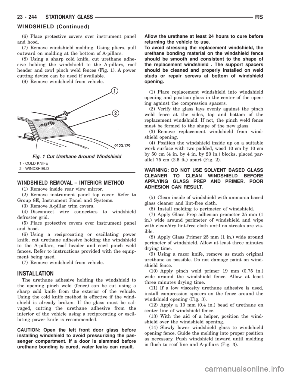
header and cowl pinch weld fences (Fig. 1). A power
cutting device can be used if available.
(9) Remove windshield from vehicle.
WINDSHIELD REMOVAL ± INTERIOR METHOD
(1) Remove inside rear view mirror.
(2) Remove instrument panel top cover. Refer to
Group 8E, Instrument Panel and Systems.
(3) Remove A-pillar trim covers.
(4) Disconnect wire connectors to windshield
defroster grid.
(5) Place protective covers over instrument panel
and hood.
(6) Using a reciprocating or oscillating power
knife, cut urethane adhesive holding the windshield
to the A-pillars, roof header and cowl pinch weld
fences. Refer to instructions provided with the equip-
ment being used.
(7) Remove windshield from vehicle.
INSTALLATION
The urethane adhesive holding the windshield to
the opening pinch weld (fence) can be cut using a
sharp cold knife from the exterior of the vehicle.
Using the cold knife method is effective if the wind-
shield is already broken. If the glass must be sal-
vaged, cutting the urethane adhesive from the
interior of the vehicle using a reciprocating or oscil-
lating power knife is recommended.
CAUTION: Open the left front door glass before
installing windshield to avoid pressurizing the pas-
senger compartment. If a door is slammed before
urethane bonding is cured, water leaks can result.Allow the urethane at least 24 hours to cure before
returning the vehicle to use.
To avoid stressing the replacement windshield, the
urethane bonding material on the windshield fence
should be smooth and consistent to the shape of
the replacement windshield . The support spacers
should be cleaned and properly installed on weld
studs or repair screws at bottom of windshield
opening.
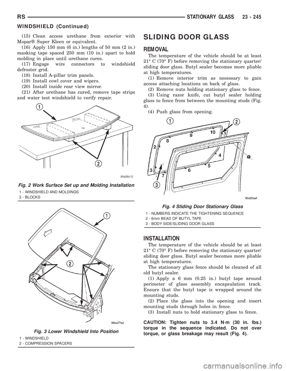
(1) Place replacement windshield into windshield
opening and position glass in the center of the open-
ing against the compression spacers.
(2) Verify the glass lays evenly against the pinch
weld fence at the sides, top and bottom of the
replacement windshield. If not, the pinch weld fence
must be formed to the shape of the new glass.
(3) Remove replacement windshield from wind-
shield opening.
(4) Position the windshield inside up on a suitable
work surface with two padded, wood 10 cm by 10 cm
by 50 cm (4 in. by 4 in. by 20 in.) blocks, placed par-
allel 75 cm (2.5 ft.) apart (Fig. 2).
WARNING: DO NOT USE SOLVENT BASED GLASS
CLEANER TO CLEAN WINDSHIELD BEFORE
APPLYING GLASS PREP AND PRIMER. POOR
ADHESION CAN RESULT.
(5) Clean inside of windshield with ammonia based
glass cleaner and lint-free cloth.
(6) Install molding to perimeter of windshield.
(7) Apply Glass Prep adhesion promoter 25 mm (1
in.) wide around perimeter of windshield and wipe
with clean/dry lint-free cloth until no streaks are vis-
ible.
(8) Apply Glass Primer 25 mm (1 in.) wide around
perimeter of windshield. Allow at least three minutes
drying time.
(9) Using a razor knife, remove as much original
urethane as possible. Do not damage paint on wind-
shield fence.
(10) Apply pinch weld primer 19 mm (0.75 in.)
wide around the windshield fence. Allow at least
three minutes drying time.
(11) If a low viscosity urethane adhesive is used,
install compression spacers on the fence around the
windshield opening (Fig. 3).
(12) Apply a 10 mm (0.4 in.) bead of urethane on
center line of windshield fence.
(13) With the aid of a helper, position the wind-
shield over the windshield opening.
(14) Slowly lower windshield glass to windshield
opening fence. Guide the molding into proper position
as necessary. Push windshield inward until molding
is flush to roof line and A-pillars (Fig. 3).
Fig. 1 Cut Urethane Around Windshield
1 - COLD KNIFE
2 - WINDSHIELD
23 - 244 STATIONARY GLASSRS
WINDSHIELD (Continued)
Page 3625 of 4284
(15) Clean access urethane from exterior with
Moparž Super Kleen or equivalent.
(16) Apply 150 mm (6 in.) lengths of 50 mm (2 in.)
masking tape spaced 250 mm (10 in.) apart to hold
molding in place until urethane cures.
(17) Engage wire connectors to windshield
defroster grid.
(18) Install A-pillar trim panels.
(19) Install cowl cover and wipers.
(20) Install inside rear view mirror.
(21) After urethane has cured, remove tape strips
and water test windshield to verify repair.SLIDING DOOR GLASS
REMOVAL
The temperature of the vehicle should be at least
21É C (70É F) before removing the stationary quarter/
sliding door glass. Butyl sealer becomes more pliable
at high temperatures.
(1) Remove interior trim as necessary to gain
access attaching locations on back of glass.
(2) Remove nuts holding stationary glass to fence.
(3) Using razor knife, cut butyl sealer holding
glass to fence from between the mounting studs (Fig.
4).
(4) Push glass from opening.
INSTALLATION
The temperature of the vehicle should be at least
21É C (70É F) before removing the stationary quarter/
sliding door glass. Butyl sealer becomes more pliable
at high temperatures.
The stationary glass fence should be cleaned of all
old butyl sealer.
(1) Applya6mm(0.25 in.) butyl tape around
perimeter of glass assembly encapsulation track.
Ensure that the butyl tape is wrapped around the
mounting studs.
(2) Place the glass into the opening and insert
mounting studs through holes in fence.
(3) Install nuts to hold stationary glass to fence.
CAUTION: Tighten nuts to 3.4 N´m (30 in. lbs.)
torque in the sequence indicated. Do not over
torque, or glass breakage may result (Fig. 4).
Fig. 2 Work Surface Set up and Molding Installation
1 - WINDSHIELD AND MOLDINGS
2 - BLOCKS
Fig. 3 Lower Windshield Into Position
1 - WINDSHIELD
2 - COMPRESSION SPACERS
Fig. 4 Sliding Door Stationary Glass
1 - NUMBERS INDICATE THE TIGHTENING SEQUENCE
2 - 6mm BEAD OF BUTYL TAPE
3 - BODY SIDE/SLIDING DOOR GLASS
RSSTATIONARY GLASS23 - 245
WINDSHIELD (Continued)
Page 3626 of 4284
(4) Install interior trim. (Refer to 23 - BODY/
DOORS - SLIDING/TRIM PANEL - INSTALLATION)
(5) Verify alignment and flushness.
QUARTER WINDOW
REMOVAL
(1) Remove C-pillar trim.
(2) Open quarter glass to vent position.
(3) Disengage quarter window retainer from vent
motor arm.
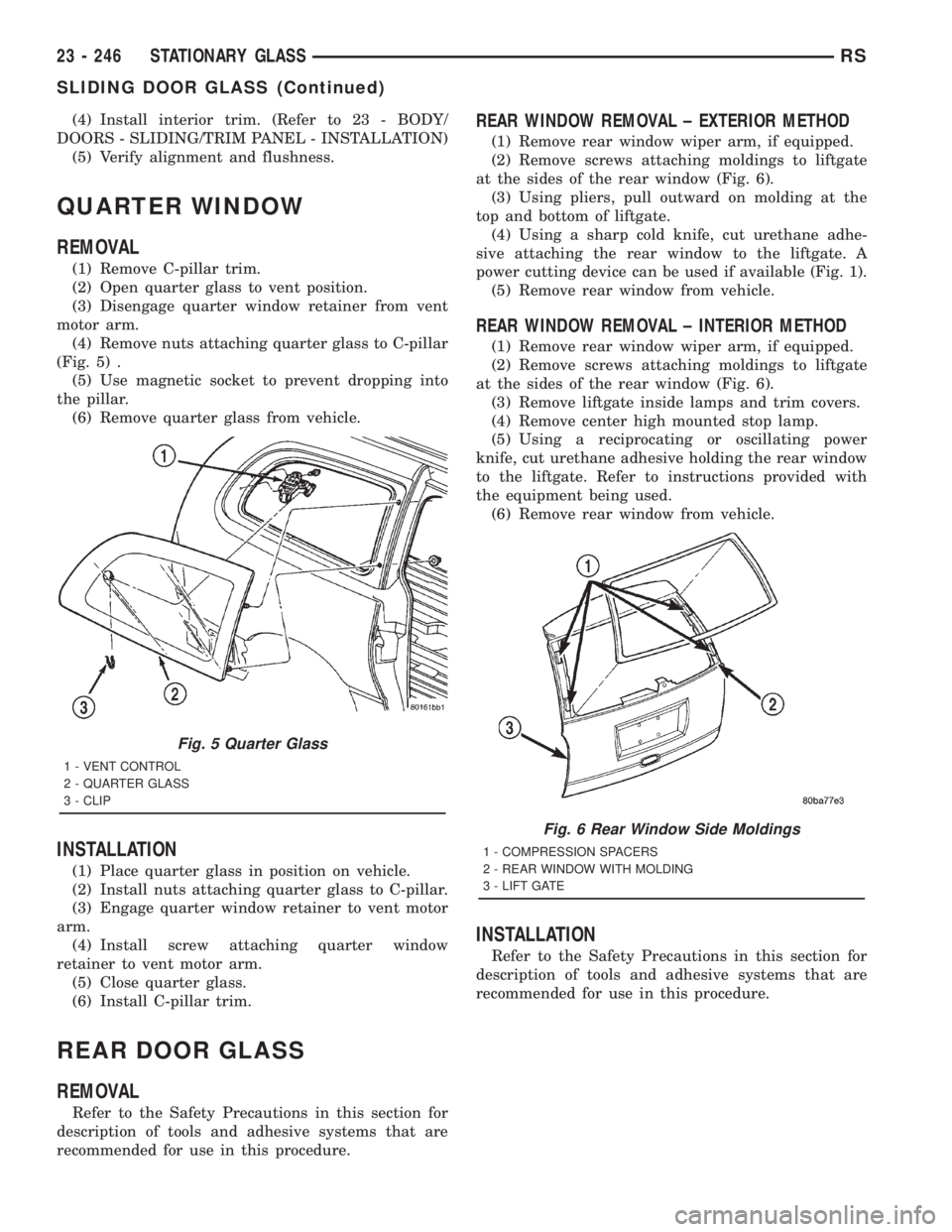
(4) Remove nuts attaching quarter glass to C-pillar
(Fig. 5) .
(5) Use magnetic socket to prevent dropping into
the pillar.
(6) Remove quarter glass from vehicle.
INSTALLATION
(1) Place quarter glass in position on vehicle.
(2) Install nuts attaching quarter glass to C-pillar.
(3) Engage quarter window retainer to vent motor
arm.
(4) Install screw attaching quarter window
retainer to vent motor arm.
(5) Close quarter glass.
(6) Install C-pillar trim.
REAR DOOR GLASS
REMOVAL
Refer to the Safety Precautions in this section for
description of tools and adhesive systems that are
recommended for use in this procedure.
REAR WINDOW REMOVAL ± EXTERIOR METHOD
(1) Remove rear window wiper arm, if equipped.
(2) Remove screws attaching moldings to liftgate
at the sides of the rear window (Fig. 6).
(3) Using pliers, pull outward on molding at the
top and bottom of liftgate.
(4) Using a sharp cold knife, cut urethane adhe-
sive attaching the rear window to the liftgate. A
power cutting device can be used if available (Fig. 1).
(5) Remove rear window from vehicle.
REAR WINDOW REMOVAL ± INTERIOR METHOD
(1) Remove rear window wiper arm, if equipped.
(2) Remove screws attaching moldings to liftgate
at the sides of the rear window (Fig. 6).
(3) Remove liftgate inside lamps and trim covers.
(4) Remove center high mounted stop lamp.
(5) Using a reciprocating or oscillating power
knife, cut urethane adhesive holding the rear window
to the liftgate. Refer to instructions provided with
the equipment being used.
(6) Remove rear window from vehicle.
INSTALLATION
Refer to the Safety Precautions in this section for
description of tools and adhesive systems that are
recommended for use in this procedure.
Fig. 5 Quarter Glass
1 - VENT CONTROL
2 - QUARTER GLASS
3 - CLIP
Fig. 6 Rear Window Side Moldings
1 - COMPRESSION SPACERS
2 - REAR WINDOW WITH MOLDING
3 - LIFT GATE
23 - 246 STATIONARY GLASSRS
SLIDING DOOR GLASS (Continued)
Page 3627 of 4284
CAUTION: Open the left front door glass before
installing rear window to avoid pressurizing the
passenger compartment. If a door is slammed
before urethane bonding is cured, water leaks can
result.
Allow the urethane at least 24 hours to cure before
returning the vehicle to use.
To avoid stressing the replacement rear window,
the urethane bonding material on the rear window
fence should be smooth and consistent to the
shape of the replacement glass .
(1) Place replacement glass into rear window open-
ing.
(2) Verify the glass lays evenly against the pinch
weld fence at the sides, top and bottom of the
replacement rear window. If not, the fence must be
formed to the shape of the new glass.
(3) Using a grease pencil, mark the glass and lift-
gate in several locations to aid installation.
(4) Remove replacement glass from liftgate open-
ing.
(5) Position the rear window inside up on a suit-
able work surface with two padded, wood 10 cm by
10 cm by 50 cm (4 in. by 4 in. by 20 in.) blocks,
placed parallel 75 cm (2.5 ft.) apart (Fig. 2).
WARNING: DO NOT USE SOLVENT BASED GLASS
CLEANER TO CLEAN REAR WINDOW BEFORE
APPLYING GLASS PREP AND PRIMER. POOR
ADHESION CAN RESULT.
(6) Clean inside of rear window with ammonia
based glass cleaner and lint-free cloth.
(7) Apply molding to top and bottom of rear win-
dow.
(8) Apply Glass Prep adhesion promoter 25 mm (1
in.) wide around perimeter of rear window and wipe
with clean/dry lint-free cloth until no streaks are vis-
ible.
(9) Apply Glass Primer 25 mm (1 in.) wide around
perimeter of rear window. Allow at least three min-
utes drying time.
(10) Apply Pinch weld Primer 19 mm (0.75 in.)
wide around the rear window fence. Allow at least
three minutes drying time.(11) If a low viscosity urethane adhesive is used,
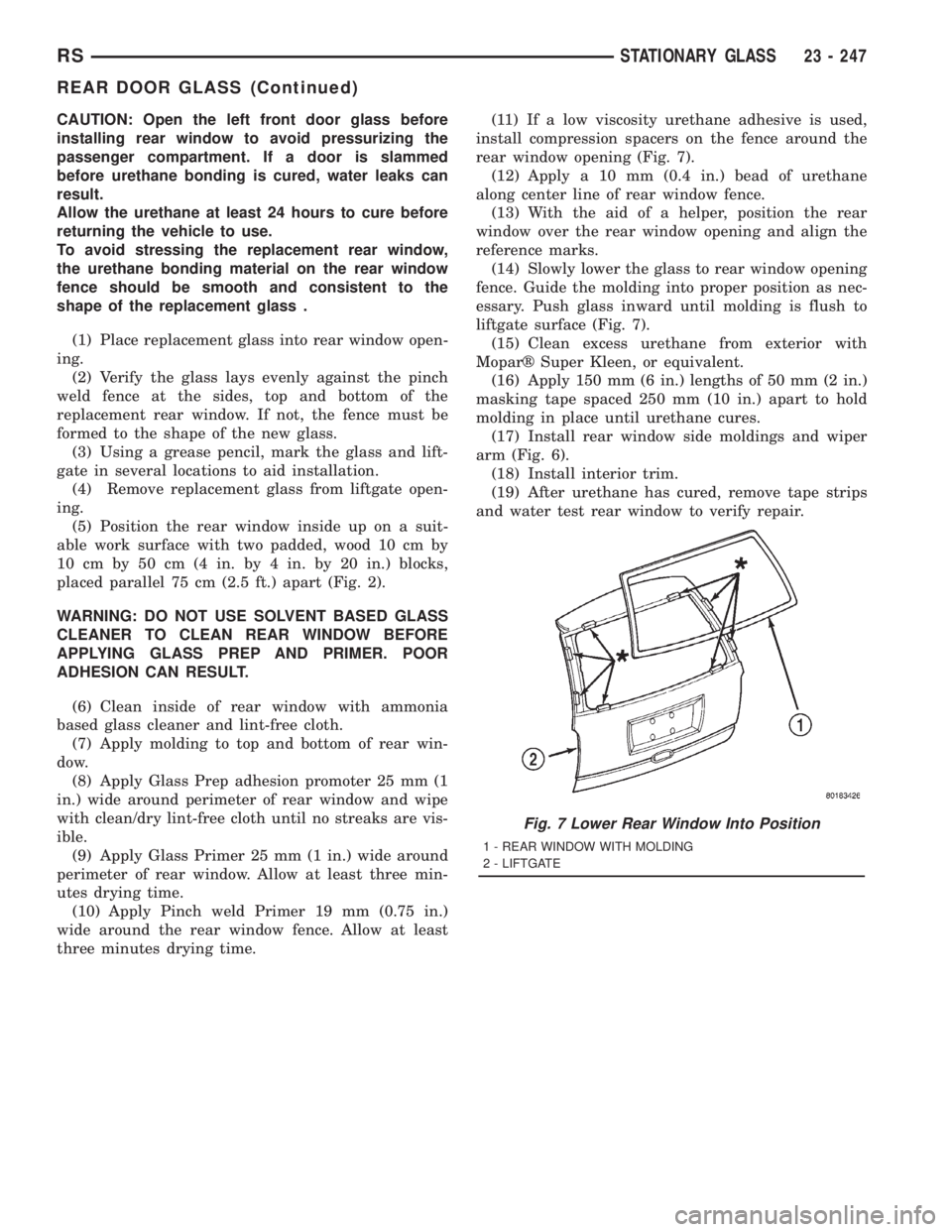
install compression spacers on the fence around the
rear window opening (Fig. 7).
(12) Apply a 10 mm (0.4 in.) bead of urethane
along center line of rear window fence.
(13) With the aid of a helper, position the rear
window over the rear window opening and align the
reference marks.
(14) Slowly lower the glass to rear window opening
fence. Guide the molding into proper position as nec-
essary. Push glass inward until molding is flush to
liftgate surface (Fig. 7).
(15) Clean excess urethane from exterior with
Moparž Super Kleen, or equivalent.
(16) Apply 150 mm (6 in.) lengths of 50 mm (2 in.)
masking tape spaced 250 mm (10 in.) apart to hold
molding in place until urethane cures.
(17) Install rear window side moldings and wiper
arm (Fig. 6).
(18) Install interior trim.
(19) After urethane has cured, remove tape strips
and water test rear window to verify repair.
Fig. 7 Lower Rear Window Into Position
1 - REAR WINDOW WITH MOLDING
2 - LIFTGATE
RSSTATIONARY GLASS23 - 247
REAR DOOR GLASS (Continued)
Page 3628 of 4284
WEATHERSTRIP/SEALS
TABLE OF CONTENTS
page page
FRONT DOOR GLASS RUN WEATHERSTRIP
REMOVAL.............................248
INSTALLATION..........................248
FRONT DOOR OUTER BELT MOLDING
REMOVAL.............................249
INSTALLATION..........................249
FRONT DOOR WEATHERSTRIP
REMOVAL.............................249INSTALLATION..........................249
SLIDING DOOR WEATHERSTRIP
REMOVAL.............................249
INSTALLATION..........................249
FRONT DOOR INNER BELT MOLDING
REMOVAL.............................250
INSTALLATION..........................250
FRONT DOOR GLASS RUN
WEATHERSTRIP
REMOVAL
(1) Remove door frame closeout moldings.
(2) Pull weatherstrip from glass run channel at
rear of door frame, working from the bottom to the
top.
(3) Disengage clip attaching weatherstrip to door
frame.
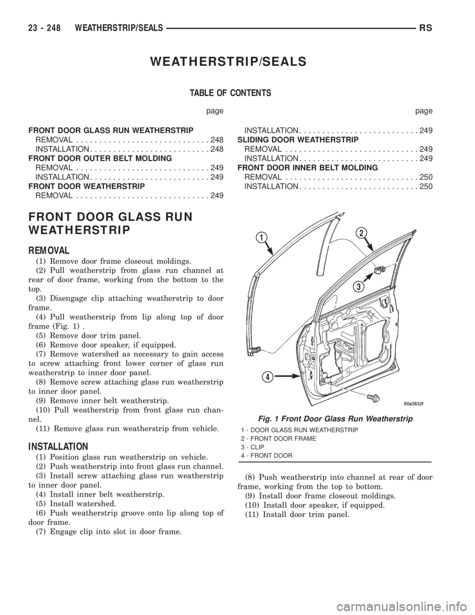
(4) Pull weatherstrip from lip along top of door
frame (Fig. 1) .
(5) Remove door trim panel.
(6) Remove door speaker, if equipped.
(7) Remove watershed as necessary to gain access
to screw attaching front lower corner of glass run
weatherstrip to inner door panel.
(8) Remove screw attaching glass run weatherstrip
to inner door panel.
(9) Remove inner belt weatherstrip.
(10) Pull weatherstrip from front glass run chan-
nel.
(11) Remove glass run weatherstrip from vehicle.
INSTALLATION
(1) Position glass run weatherstrip on vehicle.
(2) Push weatherstrip into front glass run channel.
(3) Install screw attaching glass run weatherstrip
to inner door panel.
(4) Install inner belt weatherstrip.
(5) Install watershed.
(6) Push weatherstrip groove onto lip along top of
door frame.
(7) Engage clip into slot in door frame.(8) Push weatherstrip into channel at rear of door
frame, working from the top to bottom.
(9) Install door frame closeout moldings.
(10) Install door speaker, if equipped.
(11) Install door trim panel.
Fig. 1 Front Door Glass Run Weatherstrip
1 - DOOR GLASS RUN WEATHERSTRIP
2 - FRONT DOOR FRAME
3 - CLIP
4 - FRONT DOOR
23 - 248 WEATHERSTRIP/SEALSRS
Page 3629 of 4284
FRONT DOOR OUTER BELT
MOLDING
REMOVAL
(1) Remove the side veiw mirror. (Refer to 23 -
BODY/EXTERIOR/SIDE VIEW MIRROR -
REMOVAL)
(2) Remove door trim panel.
(3) Roll door glass down.
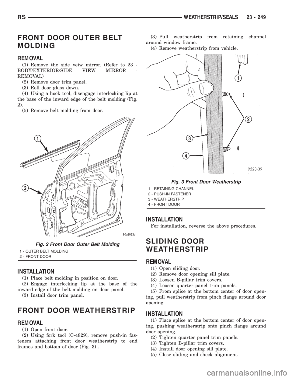
(4) Using a hook tool, disengage interlocking lip at
the base of the inward edge of the belt molding (Fig.
2).
(5) Remove belt molding from door.
INSTALLATION
(1) Place belt molding in position on door.
(2) Engage interlocking lip at the base of the
inward edge of the belt molding on door panel.
(3) Install door trim panel.
FRONT DOOR WEATHERSTRIP
REMOVAL
(1) Open front door.
(2) Using fork tool (C-4829), remove push-in fas-
teners attaching front door weatherstrip to end
frames and bottom of door (Fig. 3) .(3) Pull weatherstrip from retaining channel
around window frame.
(4) Remove weatherstrip from vehicle.
INSTALLATION
For installation, reverse the above procedures.
SLIDING DOOR
WEATHERSTRIP
REMOVAL
(1) Open sliding door.
(2) Remove door opening sill plate.
(3) Loosen B-pillar trim covers.
(4) Loosen quarter panel trim panels.
(5) From splice at the bottom center of door open-
ing, pull weatherstrip from pinch flange around door
opening.
INSTALLATION
(1) Place splice at the bottom center of door open-
ing, pushing weatherstrip onto pinch flange around
door opening.
(2) Tighten quarter panel trim panels.
(3) Tighten B-pillar trim covers.
(4) Install door opening sill plate.
(5) Close sliding and check alignment.
Fig. 2 Front Door Outer Belt Molding
1 - OUTER BELT MOLDING
2 - FRONT DOOR
Fig. 3 Front Door Weatherstrip
1 - RETAINING CHANNEL
2 - PUSH-IN FASTENER
3 - WEATHERSTRIP
4 - FRONT DOOR
RSWEATHERSTRIP/SEALS23 - 249
Page 3630 of 4284
FRONT DOOR INNER BELT
MOLDING
REMOVAL
(1) Remove door trim panel.
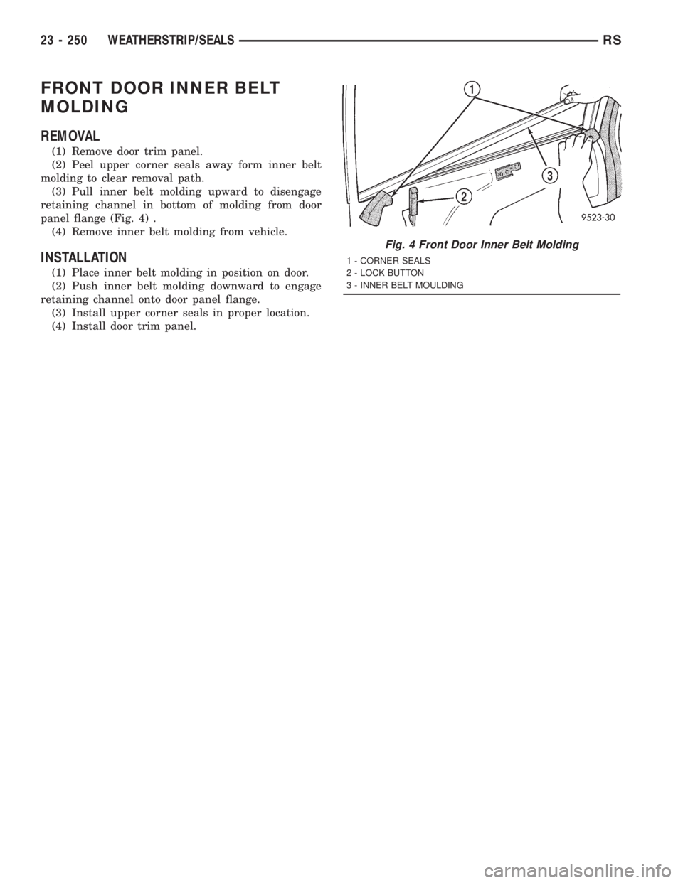
(2) Peel upper corner seals away form inner belt
molding to clear removal path.
(3) Pull inner belt molding upward to disengage
retaining channel in bottom of molding from door
panel flange (Fig. 4) .
(4) Remove inner belt molding from vehicle.
INSTALLATION
(1) Place inner belt molding in position on door.
(2) Push inner belt molding downward to engage
retaining channel onto door panel flange.
(3) Install upper corner seals in proper location.
(4) Install door trim panel.
Fig. 4 Front Door Inner Belt Molding
1 - CORNER SEALS
2 - LOCK BUTTON
3 - INNER BELT MOULDING
23 - 250 WEATHERSTRIP/SEALSRS