radio controls CHRYSLER VOYAGER 2001 Service Manual
[x] Cancel search | Manufacturer: CHRYSLER, Model Year: 2001, Model line: VOYAGER, Model: CHRYSLER VOYAGER 2001Pages: 4284, PDF Size: 83.53 MB
Page 4 of 4284
TABLE OF CONTENTS
1.0 INTRODUCTION.........................................................1
1.1SYSTEM COVERAGE...............................................1
1.2SIX-STEP TROUBLESHOOTING PROCEDURE..........................1
2.0 IDENTIFICATION OF SYSTEM.............................................1
3.0 SYSTEM DESCRIPTION AND FUNCTIONAL OPERATION......................1
3.1AIRBAG SYSTEM/OCCUPANT RESTRAINT CONTROLLER SYSTEM........2
3.1.1DRIVER AIRBAG...........................................3
3.1.2CLOCKSPRING............................................4
3.1.3PASSENGER AIRBAG......................................4
3.1.4SEAT BELT TENSIONER (SBT)...............................5
3.1.5SEAT BELT SWITCHES (SBS)................................5
3.1.6SIDE IMPACT AIRBAG CONTROL MODULE (SIACM)............5
3.1.7SEAT AIRBAGS (SAB)......................................6
3.1.8ORC/SIACM DIAGNOSTIC TROUBLE CODES..................6
3.1.9ACTIVE CODES...........................................7
3.1.10STORED CODES..........................................7
3.2AUDIO SYSTEM....................................................7
3.2.1REMOTE RADIO CONTROLS................................8
3.2.2CD CHANGER.............................................8
3.3BODY CONTROL MODULE...........................................8
3.4CHIME WARNING SYSTEM...........................................9
3.4.1CHIME PRIORITY..........................................9
3.4.2CHIME ON CONDITIONS....................................9
3.4.3WARNING LAMP ANNOUNCEMENT.........................10
3.4.4OTHER CHIME ON CONDITIONS............................10
3.5COMMUNICATION.................................................11
3.6DOOR AJAR SYSTEM..............................................12
3.7EXTERIOR LIGHTING SYSTEM......................................12
3.7.1HEADLAMP POWER......................................12
3.7.2HEADLAMP SWITCH......................................12
3.7.3PARK LAMP RELAY.......................................12
3.7.4FOG LAMP RELAY........................................12
3.7.5FOG LAMPS.............................................12
3.7.6EXTERIOR LIGHTING BATTERY SAVER......................13
3.7.7AUTO HEADLAMPS.......................................13
3.8FRONT CONTROL MODULE.........................................13
3.8.1CONTROLLED POWER FEEDS.............................13
3.8.2RELAY CONTROLS.......................................14
3.8.3ELECTRICAL INPUTS.....................................15
3.9HEATING & A/C...................................................16
3.9.1AUTOMATIC TEMPERATURE CONTROL (ATC)................16
3.9.1.1CABIN HEATER..........................................16
3.9.1.2SYSTEM OPERATION.....................................16
3.9.1.3BLOWER MOTOR OPERATION.............................16
3.9.1.4INFRARED SENSORS.....................................16
3.9.1.5REAR ATC SWITCH.......................................16
3.9.1.6COOLDOWN TESTING....................................16
3.9.1.7ACTIVE AND STORED TROUBLE CODES....................17
3.9.2MANUAL TEMPERATURE CONTROL.........................17
i
Page 11 of 4284
TABLE OF CONTENTS - Continued
REMOTE RADIO SWITCH OPEN OR *REMOTE RADIO CONTROLS
INOPERATIVE.........................................................217
REMOTE RADIO SWITCH STUCK........................................219
RIGHT OUTPUT SHORT................................................222
AUTOMATIC TEMPERATURE CONTROL
AC PRESSURE TOO HIGH (ACTIVE)......................................225
AC PRESSURE TOO LOW (ACTIVE)......................................225
AC PRESSURE TOO HIGH (STORED).....................................226
AC PRESSURE TOO LOW (STORED).....................................226
DRIVER BLEND DOOR NOT RESPONDING (STORED)......................226
DRIVER BLEND DOOR RANGE TOO LARGE (STORED).....................226
DRIVER BLEND DOOR TRAVEL TOO SMALL (STORED).....................226
FRONT IR SENSOR AND CONTROL HEAD MISMATCH (STORED).............226
FRONT IR SENSOR CHANGE TOO LARGE (STORED).......................226
FRONT IR SENSOR HIGH (STORED).....................................226
FRONT IR SENSOR LOW (STORED)......................................226
FRONT IR SENSOR NOT CALIBRATED (STORED)..........................226
FRONT KEYBOARD COMMUNICATION FAULT (STORED)....................226
FRONT KEYBOARD FAULT (STORED)....................................226
FRONT MODE DOOR NOT RESPONDING (STORED)........................226
FRONT MODE DOOR TRAVEL TOO LARGE (STORED)......................226
FRONT MODE DOOR TRAVEL TOO SMALL (STORED)......................226
PASS BLEND DOOR NOT RESPONDING (STORED).........................226
PASS BLEND DOOR TRAVEL TOO LARGE (STORED).......................226
PASS BLEND DOOR TRAVEL TOO SMALL (STORED).......................226
PCI BUS SHORTED HIGH (STORED).....................................226
PCI BUS SHORTED LOW (STORED)......................................226
REAR BLEND DOOR NOT RESPONDING (STORED)........................226
REAR BLEND DOOR RANGE TOO LARGE (STORED).......................226
REAR BLEND DOOR TRAVEL TOO SMALL (STORED).......................226
REAR FAN POT OPEN (STORED)........................................226
REAR FAN POT SHORTED (STORED)....................................226
REAR IR SENSOR HIGH (STORED)......................................226
REAR IR SENSOR LOW (STORED).......................................226
REAR IR SENSOR NOT CALIBRATED (STORED)...........................226
REAR KEYBOARD FAULT (STORED).....................................226
REAR MODE DOOR NOT RESPONDING (STORED).........................226
REAR MODE DOOR TRAVEL TOO LARGE (STORED).......................226
REAR MODE DOOR TRAVEL TOO SMALL (STORED)........................226
REAR MODE POT OPEN (STORED)......................................226
REAR MODE POT SHORTED (STORED)..................................226
RECIRC DOOR NOT RESPONDING (STORED).............................226
RECIRC DOOR TRAVEL TOO LARGE (STORED)............................226
RECIRC DOOR TRAVEL TOO SMALL (STORED)............................226
COOLDOWN TEST FAILED..............................................232
DRIVER BLEND DOOR NOT RESPONDING (ACTIVE).......................234
DRIVER BLEND DOOR TRAVEL TOO LARGE (ACTIVE)......................236
DRIVER BLEND DOOR TRAVEL TOO SMALL (ACTIVE)......................238
EEPROM CHECKSUM ERROR (ACTIVE)..................................240
EVAP TEMP SENSOR OPEN............................................241
EVAP TEMP SENSOR SHORTED.........................................243
FRONT IR SENSOR AND CONTROL HEAD MISMATCH (ACTIVE)..............245
viii
Page 27 of 4284
TABLE OF CONTENTS - Continued
RIGHT SLIDING DOOR CONTROL MODULE C1 (POWER SLIDING DOOR) - BLACK
8 WAY ..............................................................1082
RIGHT SLIDING DOOR CONTROL MODULE C2 (POWER SLIDING DOOR) -
BLACK/RED 20 WAY..................................................1082
RIGHT SLIDING DOOR LATCH SENSING SWITCH (POWER SLIDING DOOR) -
BLACK 6 WAY........................................................1082
RIGHT SLIDING DOOR LOCK MOTOR (POWER SLIDING DOOR) - BLACK 4
WAY................................................................1083
RIGHT SLIDING DOOR LOCK MOTOR/AJAR SWITCH (MANUAL SLIDING DOOR) -
BLACK 4 WAY........................................................1083
RIGHT SLIDING DOOR MOTOR (POWER SLIDING DOOR) - BLACK 8 WAY. . . .1083
SENTRY KEY IMMOBILIZER MODULE - BLACK 6 WAY.....................1083
SIREN (UNITED KINGDOM) - BLACK 4 WAY..............................1083
THATCHAM ALARM MODULE C1 (UNITED KINGDOM) - BLACK 16 WAY.......1084
THATCHAM ALARM MODULE C2 (UNITED KINGDOM) - WHITE 4 WAY........1084
TRANSMISSION CONTROL MODULE (EATX) - BLACK 60 WAY..............1085
TXV SOLENOID (ATC)-2WAY.........................................1086
10.0 SCHEMATIC DIAGRAMS...............................................1087
10.1AIRBAG SYSTEM................................................1087
10.2AUDIO SYSTEM.................................................1088
10.2.1PREMIUM.............................................1088
10.2.2BASE.................................................1089
10.2.3CD CHANGER.........................................1090
10.2.4REMOTE RADIO CONTROLS.............................1091
10.3CABIN HEATER.................................................1092
10.4AUTOMATIC TEMPERATURE CONTROL SYSTEM....................1093
10.4.1FRONT ATC............................................1093
10.4.2REAR ATC.............................................1094
10.5COMMUNICATION...............................................1095
10.5.1PCM COMMUNICATION.................................1096
10.5.2ECM & CABIN HEATER ASSIST COMMUNICATION - DIESEL
ONLY.................................................1096
10.6DOOR AJAR WITH POWER SLIDING DOORS........................1097
10.7DOOR AJAR WITHOUT POWER SLIDING DOORS....................1098
10.8EXTERIOR LIGHTING............................................1099
10.9IGNITION SWITCH...............................................1100
10.10INSTRUMENT CLUSTER Ð BASE..................................1101
10.11INSTRUMENT CLUSTER & MESSAGE CENTER......................1102
10.12INTELLIGENT POWER MODULE/BODY CONTROL MODULE POWER AND
GROUNDS......................................................1103
10.13INTERIOR LIGHTING.............................................1104
10.14MANUAL TEMPERATURE CONTROLS..............................1105
10.14.1BASE MANUAL TEMPERATURE CONTROL SYSTEM LHD.....1105
10.14.2BASE MANUAL TEMPERATURE CONTROL SYSTEM RHD....1106
10.14.3DUAL-ZONE MANUAL TEMPERATURE CONTROL SYSTEM
LHD ..................................................1107
10.14.4DUAL-ZONE MANUAL TEMPERATURE CONTROL SYSTEM
RHD..................................................1108
10.14.5BLOWER MOTOR.......................................1109
10.15MEMORY SYSTEM...............................................1110
10.16OVERHEAD CONSOLE...........................................1111
xxiv
Page 37 of 4284
this type of system would only refer to this circuit.
A faulty speaker could not cause this DTC.
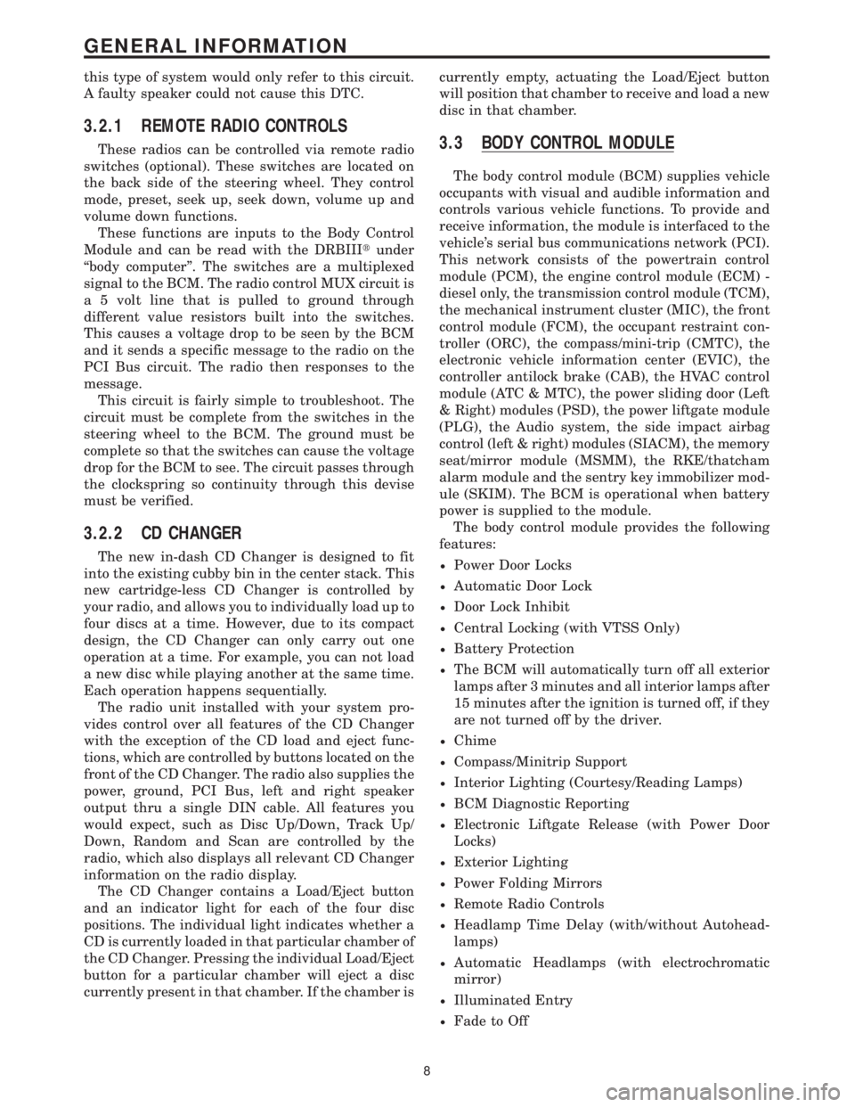
3.2.1 REMOTE RADIO CONTROLS
These radios can be controlled via remote radio
switches (optional). These switches are located on
the back side of the steering wheel. They control
mode, preset, seek up, seek down, volume up and
volume down functions.
These functions are inputs to the Body Control
Module and can be read with the DRBIIItunder
ªbody computerº. The switches are a multiplexed
signal to the BCM. The radio control MUX circuit is
a 5 volt line that is pulled to ground through
different value resistors built into the switches.
This causes a voltage drop to be seen by the BCM
and it sends a specific message to the radio on the
PCI Bus circuit. The radio then responses to the
message.
This circuit is fairly simple to troubleshoot. The
circuit must be complete from the switches in the
steering wheel to the BCM. The ground must be
complete so that the switches can cause the voltage
drop for the BCM to see. The circuit passes through
the clockspring so continuity through this devise
must be verified.
3.2.2 CD CHANGER
The new in-dash CD Changer is designed to fit
into the existing cubby bin in the center stack. This
new cartridge-less CD Changer is controlled by
your radio, and allows you to individually load up to
four discs at a time. However, due to its compact
design, the CD Changer can only carry out one
operation at a time. For example, you can not load
a new disc while playing another at the same time.
Each operation happens sequentially.
The radio unit installed with your system pro-
vides control over all features of the CD Changer
with the exception of the CD load and eject func-
tions, which are controlled by buttons located on the
front of the CD Changer. The radio also supplies the
power, ground, PCI Bus, left and right speaker
output thru a single DIN cable. All features you
would expect, such as Disc Up/Down, Track Up/
Down, Random and Scan are controlled by the
radio, which also displays all relevant CD Changer
information on the radio display.
The CD Changer contains a Load/Eject button
and an indicator light for each of the four disc
positions. The individual light indicates whether a
CD is currently loaded in that particular chamber of
the CD Changer. Pressing the individual Load/Eject
button for a particular chamber will eject a disc
currently present in that chamber. If the chamber iscurrently empty, actuating the Load/Eject button
will position that chamber to receive and load a new
disc in that chamber.
3.3 BODY CONTROL MODULE
The body control module (BCM) supplies vehicle
occupants with visual and audible information and
controls various vehicle functions. To provide and
receive information, the module is interfaced to the
vehicle's serial bus communications network (PCI).
This network consists of the powertrain control
module (PCM), the engine control module (ECM) -
diesel only, the transmission control module (TCM),
the mechanical instrument cluster (MIC), the front
control module (FCM), the occupant restraint con-
troller (ORC), the compass/mini-trip (CMTC), the
electronic vehicle information center (EVIC), the
controller antilock brake (CAB), the HVAC control
module (ATC & MTC), the power sliding door (Left
& Right) modules (PSD), the power liftgate module
(PLG), the Audio system, the side impact airbag
control (left & right) modules (SIACM), the memory
seat/mirror module (MSMM), the RKE/thatcham
alarm module and the sentry key immobilizer mod-
ule (SKIM). The BCM is operational when battery
power is supplied to the module.
The body control module provides the following
features:
²Power Door Locks
²Automatic Door Lock
²Door Lock Inhibit
²Central Locking (with VTSS Only)
²Battery Protection
²The BCM will automatically turn off all exterior
lamps after 3 minutes and all interior lamps after
15 minutes after the ignition is turned off, if they
are not turned off by the driver.
²Chime
²Compass/Minitrip Support
²Interior Lighting (Courtesy/Reading Lamps)
²BCM Diagnostic Reporting
²Electronic Liftgate Release (with Power Door
Locks)
²Exterior Lighting
²Power Folding Mirrors
²Remote Radio Controls
²Headlamp Time Delay (with/without Autohead-
lamps)
²Automatic Headlamps (with electrochromatic
mirror)
²Illuminated Entry
²Fade to Off
8
GENERAL INFORMATION
Page 43 of 4284
EATX power
The electronic automatic 4 speed transmission
module is powered when the ignition switch is in
the UNLOCK, RUN or START positions. This cir-
cuit is electronically controlled and continuously
monitored for malfunctions. Power is supplied
through pin 27 of the FCM connector.
Front washer motor
The front washer switch is a direct input to the
BCM. The BCM sends a PCI Bus message to the
FCM informing it of a request to wash. The front
washer motor is then powered through low side
control inside the FCM. This circuit is electronically
controlled and continuously monitored for malfunc-
tions. In addition, the FCM electronically protects
the washer motor from system voltages higher than
16 volts by automatically switching off the low side
circuit. The low side circuit is connected to pin 45 in
the FCM connector.
Rear washer motor
The rear washer switch is a direct input to the
BCM. The BCM sends a PCI Bus message to the
FCM informing it of a request to wash. The rear
washer motor is then powered through low side
control inside the FCM. This circuit is electronically
controlled and continuously monitored for malfunc-
tions. In addition, the FCM electronically protects
the washer motor from system voltages higher than
16 volts by automatically switching off the low side
circuit. The low side circuit is connected to pin 46 in
the FCM connector.
Brake shift interlock system
The brake shift interlock solenoid receives power
from both high side and low side controls inside the
FCM. The high side control is on the same circuit as
the EATX module power, and the low side control
comes through pin 47 of the FCM connector. The
solenoid is controlled by the low side driver when
the brake pedal is pressed. Both circuits are contin-
uously monitored for malfunctions.
3.8.2 RELAY CONTROLS
Fog lamp relay
The fog lamp switch is a direct input to the BCM.
The BCM sends a PCI Bus message to the FCM
informing it to turn on the fog lamp relay. The fog
lamp relay is then powered through low side control
on pin 33 of the FCM. This circuit is electronically
controlled and continuously monitored for malfunc-
tions. Fog lamp functionality is not equipped on all
vehicles. The FCM ªlearnsº that the vehicle is
equipped with fog lamps by reading the BCM PCI
Bus message.
Park lamp relay
The park lamp switch is a direct input to the
BCM. The BCM sends a PCI Bus message to the
FCM informing it to turn on the park lamp relay.
The park lamp relay is then powered through lowside control on pin 13 of the FCM. This circuit is
electronically controlled and continuously moni-
tored for malfunctions.
Front wiper on relay
The front wiper switch is a direct input to the
BCM. The BCM sends a PCI Bus message to the
FCM informing it to turn on the front wiper on
relay. The front wiper on relay is then powered
through low side control on pin 14 of the FCM. This
circuit is electronically controlled and continuously
monitored for malfunctions.
Front wiper high/low relay
The front wiper switch is a direct input to the
BCM. The BCM sends a PCI Bus message to the
FCM informing it to turn on the front wiper high/
low relay. The relay switches power between the low
speed and high speed windings of the wiper motor.
The front wiper high/low relay is powered through
low side control on pin 34 of the FCM. This circuit is
electronically controlled and continuously moni-
tored for malfunctions.
Accessory relay
The accessory relay works in conjunction with the
FCM's power accessory delay feature to control the
operation of the radio, power windows, washer
motors, wiper motors and power outlet. The acces-
sory relay is turned on through low side control on
pin 35 of the FCM. This circuit is electronically
controlled and continuously monitored for malfunc-
tions. Depending on the ignition switch position,
the accessory relay will remain on or will time-out
and turn off. The accessory relay remains on in the
RUN and ACCY positions of the ignition switch. In
the UNLK and OFF positions, the relay will remain
energized for 45 seconds then turn off. During this
time-out period, if the driver or passenger doors are
opened, the relay will turn off immediately. While
the ignition switch is in the START position, the
relay will also drop-out, then resume operation.
Accessory relay operation is most noticeable by
observing the operation of the radio or blower
functions.
Horn relay
The horn relay operates through a direct wire
input to the FCM from the horn switch (FCM pin
17) , or a PCI Bus message from the BCM. The relay
responds to the horn switch, remote door lock and
VTA alarm functions. The horn relay is powered
through low side control on pin 10 of the FCM.
Under normal operating conditions, if the horn is
pressed for longer than 30 seconds, the FCM will
automatically deactivate the horn to prevent dam-
age to it. The FCM will re-activate control of the
relay after a 25 second cool-down period. This
circuit is electronically controlled and continuously
monitored for malfunctions.
14
GENERAL INFORMATION
Page 51 of 4284
On vehicles equipped with AutoStick, the display
includes an O/D OFF indicator that is illuminated
when the driver presses the Overdrive Off button
on the transaxle shifter.
3.11.1 INSTRUMENT CLUSTER SELF TEST
1. Depress and hold the Odometer Reset button.
2. Turn the ignition switch to the RUN/START
position.
3. Release the Odometer reset button.
The Instrument Cluster will illuminate all indi-
cators and step the gauges through several calibra-
tion points. Also, the odometer will display any
stored codes that may have set.
3.11.2 MESSAGE CENTER
The Message Center is located above the brow of
the Instrument Cluster. It houses the following
warning indicators: Check Engine/Service Engine
Soon, high beam, left and right turn signals, Secu-
rity Alarm Set, and low oil pressure. On base
models equipped with the three-speed transaxle,
these indicators appear in the face of the cluster.
The Security Alarm set indicator is a red circle.
Activation of Instrument Cluster indicators is
coordinated with indicators in the message center
and EVIC to avoid redundancy. A revised safety
standard now requires that the seat belt warning
lamp in the Instrument Cluster remain lit if the
driver seat belt is not buckled. A headlamp out ISO
indicator has been added to the Instrument Cluster
to alert the driver when a headlamp is not function-
ing.
3.12 INTERIOR LIGHTING
3.12.1 COURTESY LAMP CONTROL
The body controller has direct control over all of
the vehicle's courtesy lamps. The body computer
will illuminate the courtesy lamps under any of the
following conditions:
1. Any door ajar and courtesy lamp switch on the
headlamp switch is not in the dome off position.
2. The courtesy lamp switch on the headlamp
switch is in the dome on position.
3. A Remote Keyless Entry unlock message is re-
ceived.
4. Driver door unlocked with key (with VTSS only).
3.12.2 ILLUMINATED ENTRY
Illuminated entry will be initiated when the cus-
tomer enters the vehicle by unlocking the doors
with the key fob, or with the key if the vehicle is
equipped with vehicle theft alarm. Upon exiting thevehicle, if the lock button is pressed with a door
open, illuminated entry will cancel when the door
closes. If the doors are closed and the ignition
switch is turned on, the illuminated entry also
cancels. The illuminated entry feature will not
operate if the courtesy lamp switch is in the dome
off position.
3.12.3 INTERIOR LIGHTING BATTERY
SAVER
If any of the interior lamps are left on after the
ignition is turned off, the BCM will turn them off
after 8 minutes. To return to normal operation, the
courtesy lamps will operate after the dome lamp
switch or door ajar switch changes state. The glove
box and switched reading lamps require that the
ignition be turned to the on/acc position.
3.13 MEMORY SYSTEM
The memory system consists of power driver 's
seat, power mirrors and radio presets. The Memory
Seat/Mirror Module (MSMM) is located under the
driver 's seat. It receives input from the following:
driver 's manual 8-way seat switch, driver 's seat
position sensors, PCI bus circuits, and the power
mirror sensors. The module uses these inputs to
perform the following functions: position the driv-
er 's memory seat, both exterior mirrors (during
recalls), and send/receive the memory system infor-
mation over the PCI bus.
The Memory Set Switch is wired to the Body
Control Module (BCM). When a button (either #1 or
#2) is pressed on the set switch causes the to BCM
send a message to the MSMM which in turn sends
a motion status messages to the BCM. If the BCM
receives no motion from the MSMM it will send a
recall message to the MSMM and radio (once igni-
tion is in run or accessory). The MSMM will in turn
position the drivers seat, both mirrors along with
recalling the radio presets. If the drivers seat or
either exterior mirror is inoperative from its own
respective switches, use the service information
and schematic to diagnose the problem. This man-
ual addresses the memory problems only and it is
assumed there is not a basic component failure.
3.13.1 POWER SEAT
The memory power seat provides the driver with
2 position settings for the driver 's seat. Each power
seat motor is connected to the MSMM with two
motor drive circuits. Each circuit is switched be-
tween battery and ground. By being able to bi-
directionally drive the circuits, the MSMM controls
the movement of the motors based on input from
the power seat switch or from the position sensors
when performing a memory recall. Each motor
22
GENERAL INFORMATION
Page 246 of 4284
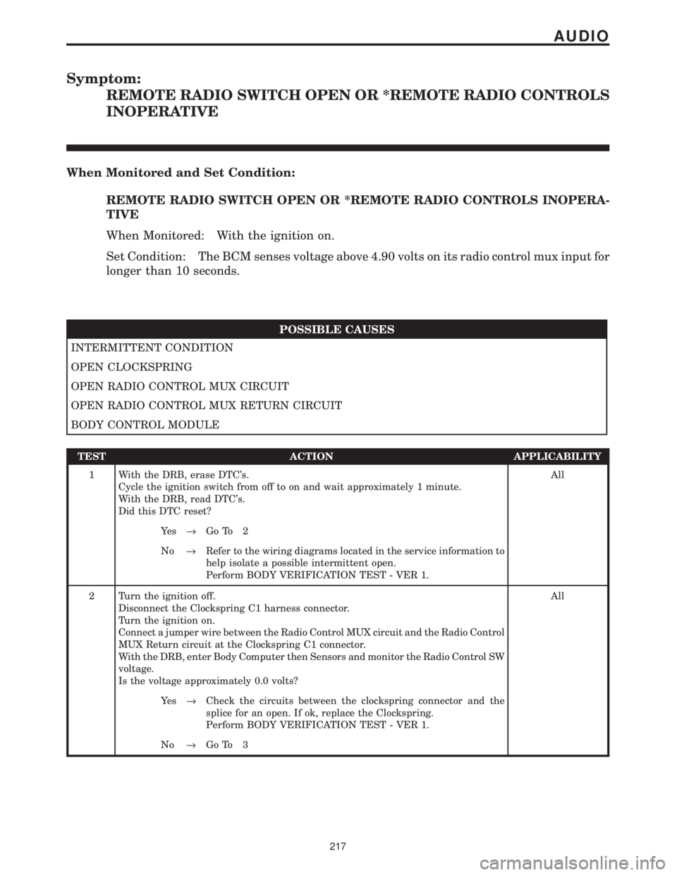
Symptom:
REMOTE RADIO SWITCH OPEN OR *REMOTE RADIO CONTROLS
INOPERATIVE
When Monitored and Set Condition:
REMOTE RADIO SWITCH OPEN OR *REMOTE RADIO CONTROLS INOPERA-
TIVE
When Monitored: With the ignition on.
Set Condition: The BCM senses voltage above 4.90 volts on its radio control mux input for
longer than 10 seconds.
POSSIBLE CAUSES
INTERMITTENT CONDITION
OPEN CLOCKSPRING
OPEN RADIO CONTROL MUX CIRCUIT
OPEN RADIO CONTROL MUX RETURN CIRCUIT
BODY CONTROL MODULE
TEST ACTION APPLICABILITY
1 With the DRB, erase DTC's.
Cycle the ignition switch from off to on and wait approximately 1 minute.
With the DRB, read DTC's.
Did this DTC reset?All
Ye s®Go To 2
No®Refer to the wiring diagrams located in the service information to
help isolate a possible intermittent open.
Perform BODY VERIFICATION TEST - VER 1.
2 Turn the ignition off.
Disconnect the Clockspring C1 harness connector.
Turn the ignition on.
Connect a jumper wire between the Radio Control MUX circuit and the Radio Control
MUX Return circuit at the Clockspring C1 connector.
With the DRB, enter Body Computer then Sensors and monitor the Radio Control SW
voltage.
Is the voltage approximately 0.0 volts?All
Ye s®Check the circuits between the clockspring connector and the
splice for an open. If ok, replace the Clockspring.
Perform BODY VERIFICATION TEST - VER 1.
No®Go To 3
217
AUDIO
Page 247 of 4284
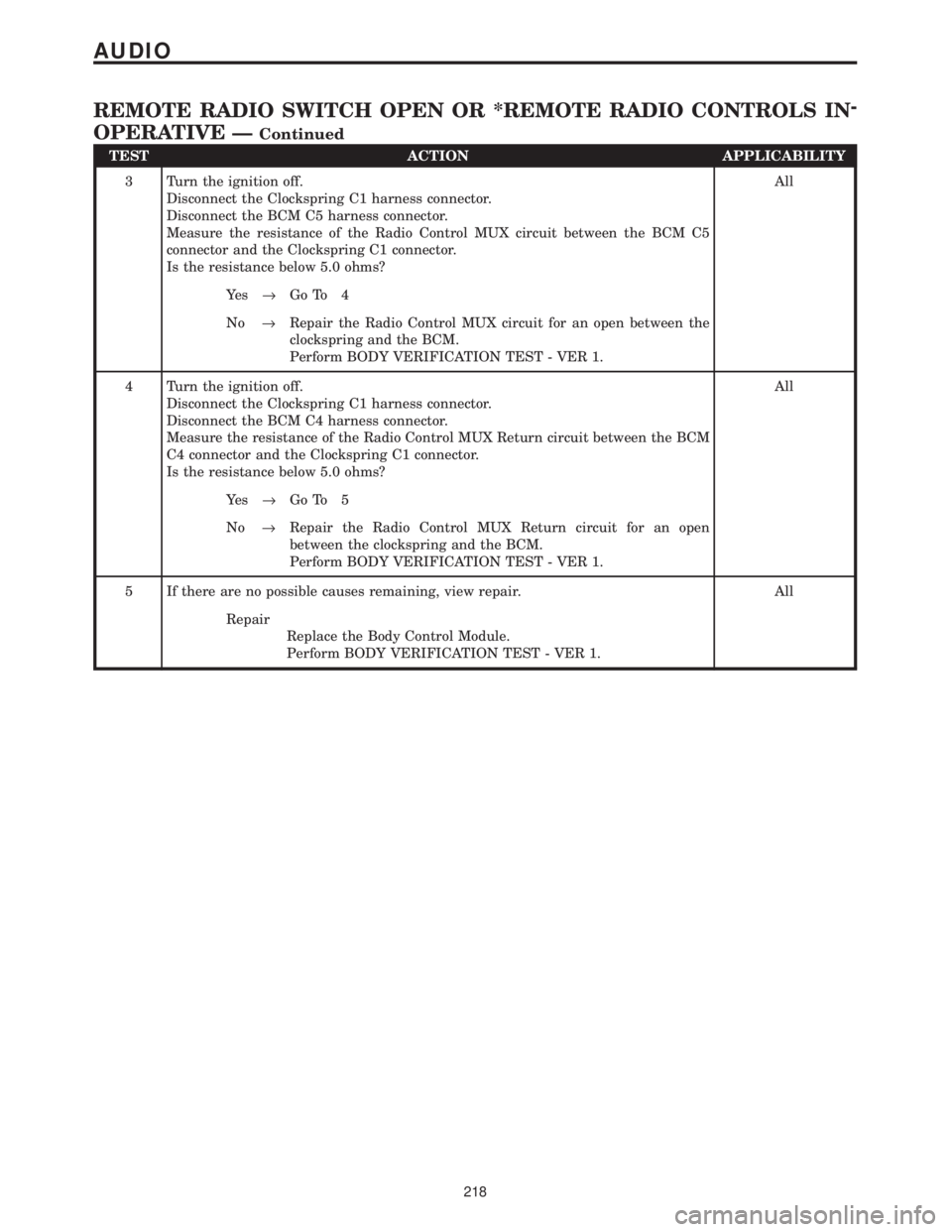
TEST ACTION APPLICABILITY
3 Turn the ignition off.
Disconnect the Clockspring C1 harness connector.
Disconnect the BCM C5 harness connector.
Measure the resistance of the Radio Control MUX circuit between the BCM C5
connector and the Clockspring C1 connector.
Is the resistance below 5.0 ohms?All
Ye s®Go To 4
No®Repair the Radio Control MUX circuit for an open between the
clockspring and the BCM.
Perform BODY VERIFICATION TEST - VER 1.
4 Turn the ignition off.
Disconnect the Clockspring C1 harness connector.
Disconnect the BCM C4 harness connector.
Measure the resistance of the Radio Control MUX Return circuit between the BCM
C4 connector and the Clockspring C1 connector.
Is the resistance below 5.0 ohms?All
Ye s®Go To 5
No®Repair the Radio Control MUX Return circuit for an open
between the clockspring and the BCM.
Perform BODY VERIFICATION TEST - VER 1.
5 If there are no possible causes remaining, view repair. All
Repair
Replace the Body Control Module.
Perform BODY VERIFICATION TEST - VER 1.
218
AUDIO
REMOTE RADIO SWITCH OPEN OR *REMOTE RADIO CONTROLS IN-
OPERATIVE Ð
Continued
Page 1120 of 4284
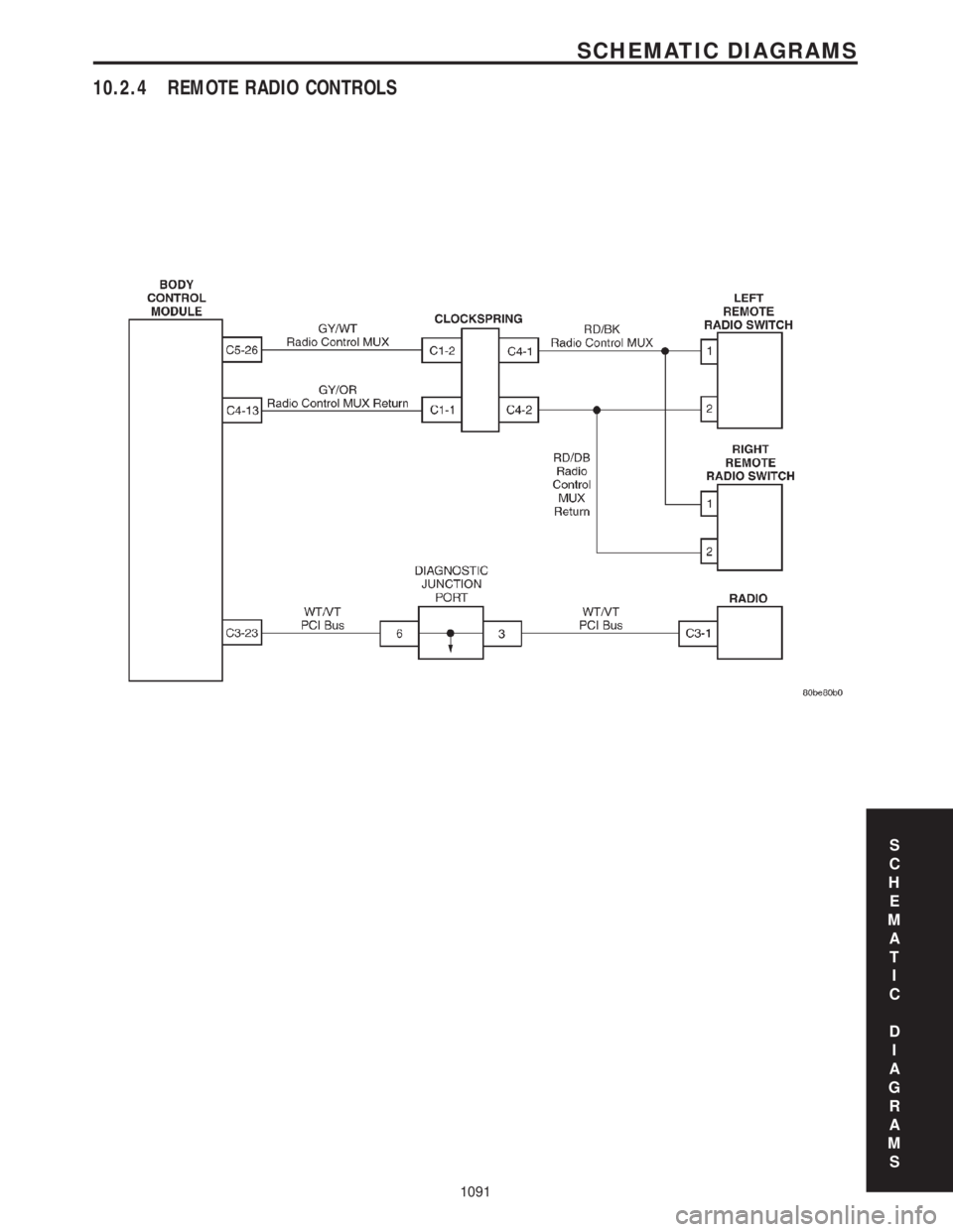
10.2.4 REMOTE RADIO CONTROLS
S
C
H
E
M
A
T
I
C
D
I
A
G
R
A
M
S
1091
SCHEMATIC DIAGRAMS
Page 1814 of 4284
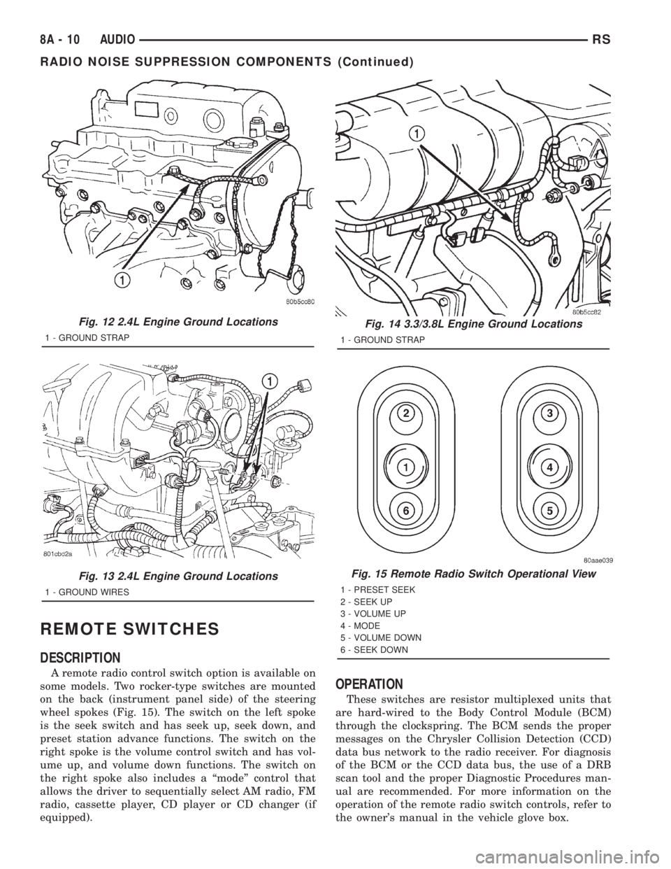
REMOTE SWITCHES
DESCRIPTION
A remote radio control switch option is available on
some models. Two rocker-type switches are mounted
on the back (instrument panel side) of the steering
wheel spokes (Fig. 15). The switch on the left spoke
is the seek switch and has seek up, seek down, and
preset station advance functions. The switch on the
right spoke is the volume control switch and has vol-
ume up, and volume down functions. The switch on
the right spoke also includes a ªmodeº control that
allows the driver to sequentially select AM radio, FM
radio, cassette player, CD player or CD changer (if
equipped).
OPERATION
These switches are resistor multiplexed units that
are hard-wired to the Body Control Module (BCM)
through the clockspring. The BCM sends the proper
messages on the Chrysler Collision Detection (CCD)
data bus network to the radio receiver. For diagnosis
of the BCM or the CCD data bus, the use of a DRB
scan tool and the proper Diagnostic Procedures man-
ual are recommended. For more information on the
operation of the remote radio switch controls, refer to
the owner's manual in the vehicle glove box.
Fig. 12 2.4L Engine Ground Locations
1 - GROUND STRAP
Fig. 13 2.4L Engine Ground Locations
1 - GROUND WIRES
Fig. 14 3.3/3.8L Engine Ground Locations
1 - GROUND STRAP
Fig. 15 Remote Radio Switch Operational View
1 - PRESET SEEK
2 - SEEK UP
3 - VOLUME UP
4 - MODE
5 - VOLUME DOWN
6 - SEEK DOWN
8A - 10 AUDIORS
RADIO NOISE SUPPRESSION COMPONENTS (Continued)