CHRYSLER VOYAGER 2001 Service Manual
Manufacturer: CHRYSLER, Model Year: 2001, Model line: VOYAGER, Model: CHRYSLER VOYAGER 2001Pages: 4284, PDF Size: 83.53 MB
Page 4251 of 4284
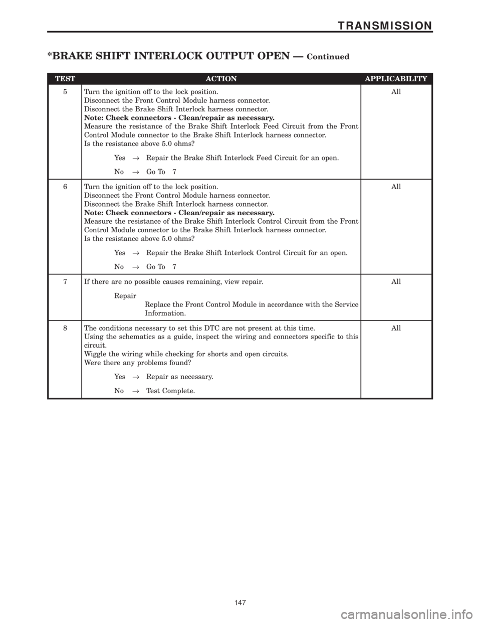
TEST ACTION APPLICABILITY
5 Turn the ignition off to the lock position.
Disconnect the Front Control Module harness connector.
Disconnect the Brake Shift Interlock harness connector.
Note: Check connectors - Clean/repair as necessary.
Measure the resistance of the Brake Shift Interlock Feed Circuit from the Front
Control Module connector to the Brake Shift Interlock harness connector.
Is the resistance above 5.0 ohms?All
Ye s®Repair the Brake Shift Interlock Feed Circuit for an open.
No®Go To 7
6 Turn the ignition off to the lock position.
Disconnect the Front Control Module harness connector.
Disconnect the Brake Shift Interlock harness connector.
Note: Check connectors - Clean/repair as necessary.
Measure the resistance of the Brake Shift Interlock Control Circuit from the Front
Control Module connector to the Brake Shift Interlock harness connector.
Is the resistance above 5.0 ohms?All
Ye s®Repair the Brake Shift Interlock Control Circuit for an open.
No®Go To 7
7 If there are no possible causes remaining, view repair. All
Repair
Replace the Front Control Module in accordance with the Service
Information.
8 The conditions necessary to set this DTC are not present at this time.
Using the schematics as a guide, inspect the wiring and connectors specific to this
circuit.
Wiggle the wiring while checking for shorts and open circuits.
Were there any problems found?All
Ye s®Repair as necessary.
No®Test Complete.
147
TRANSMISSION
*BRAKE SHIFT INTERLOCK OUTPUT OPEN ÐContinued
Page 4252 of 4284
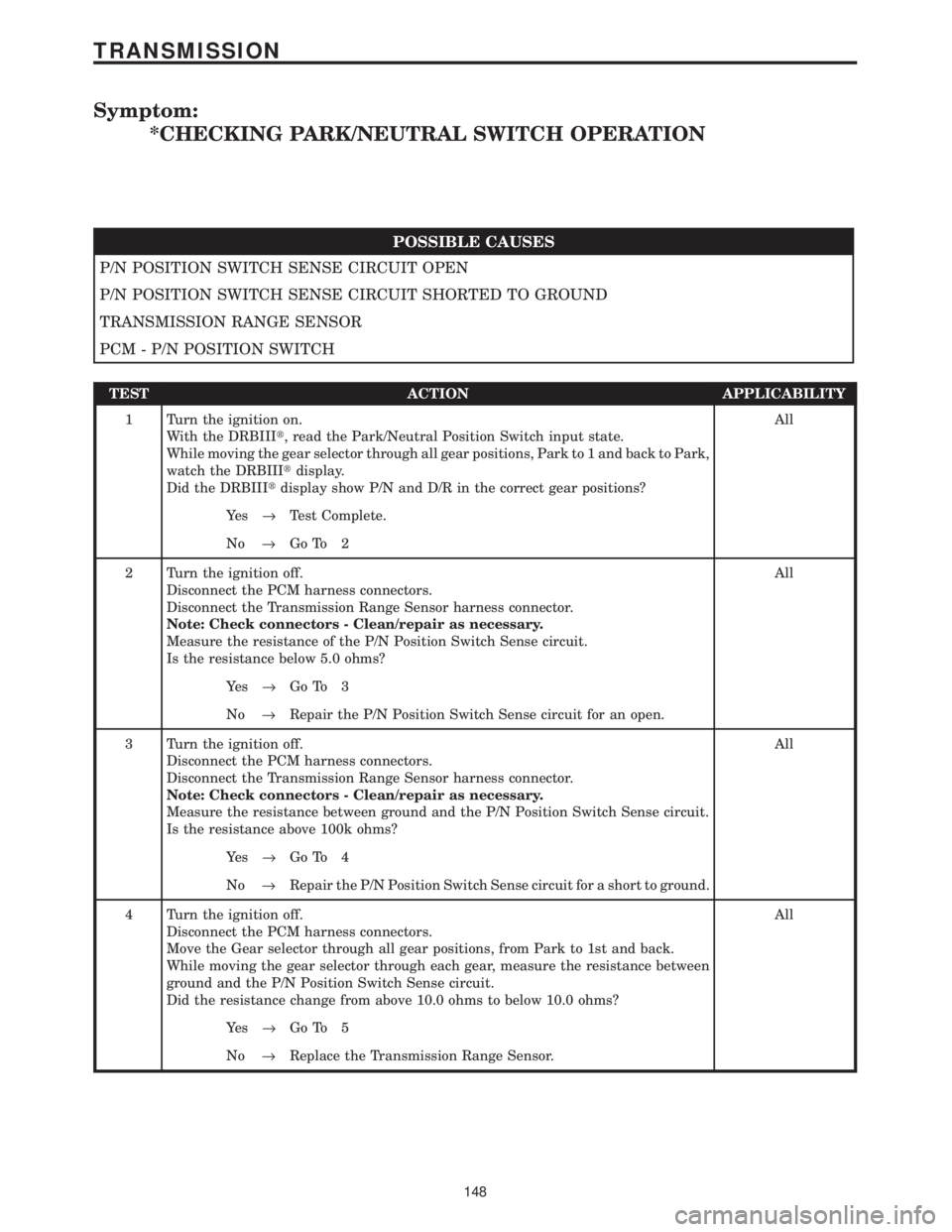
Symptom:
*CHECKING PARK/NEUTRAL SWITCH OPERATION
POSSIBLE CAUSES
P/N POSITION SWITCH SENSE CIRCUIT OPEN
P/N POSITION SWITCH SENSE CIRCUIT SHORTED TO GROUND
TRANSMISSION RANGE SENSOR
PCM - P/N POSITION SWITCH
TEST ACTION APPLICABILITY
1 Turn the ignition on.
With the DRBIIIt, read the Park/Neutral Position Switch input state.
While moving the gear selector through all gear positions, Park to 1 and back to Park,
watch the DRBIIItdisplay.
Did the DRBIIItdisplay show P/N and D/R in the correct gear positions?All
Ye s®Test Complete.
No®Go To 2
2 Turn the ignition off.
Disconnect the PCM harness connectors.
Disconnect the Transmission Range Sensor harness connector.
Note: Check connectors - Clean/repair as necessary.
Measure the resistance of the P/N Position Switch Sense circuit.
Is the resistance below 5.0 ohms?All
Ye s®Go To 3
No®Repair the P/N Position Switch Sense circuit for an open.
3 Turn the ignition off.
Disconnect the PCM harness connectors.
Disconnect the Transmission Range Sensor harness connector.
Note: Check connectors - Clean/repair as necessary.
Measure the resistance between ground and the P/N Position Switch Sense circuit.
Is the resistance above 100k ohms?All
Ye s®Go To 4
No®Repair the P/N Position Switch Sense circuit for a short to ground.
4 Turn the ignition off.
Disconnect the PCM harness connectors.
Move the Gear selector through all gear positions, from Park to 1st and back.
While moving the gear selector through each gear, measure the resistance between
ground and the P/N Position Switch Sense circuit.
Did the resistance change from above 10.0 ohms to below 10.0 ohms?All
Ye s®Go To 5
No®Replace the Transmission Range Sensor.
148
TRANSMISSION
Page 4253 of 4284

TEST ACTION APPLICABILITY
5 If there are no possible causes remaining, view repair. All
Repair
Replace and program the Powertrain Control Module in accor-
dance with the Service Information.
Perform POWERTRAIN VERIFICATION TEST VER - 2.
149
TRANSMISSION
*CHECKING PARK/NEUTRAL SWITCH OPERATION ÐContinued
Page 4254 of 4284
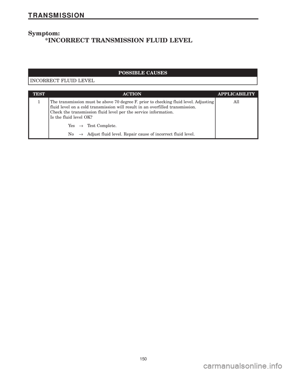
Symptom:
*INCORRECT TRANSMISSION FLUID LEVEL
POSSIBLE CAUSES
INCORRECT FLUID LEVEL
TEST ACTION APPLICABILITY
1 The transmission must be above 70 degree F. prior to checking fluid level. Adjusting
fluid level on a cold transmission will result in an overfilled transmission.
Check the transmission fluid level per the service information.
Is the fluid level OK?All
Ye s®Test Complete.
No®Adjust fluid level. Repair cause of incorrect fluid level.
150
TRANSMISSION
Page 4255 of 4284
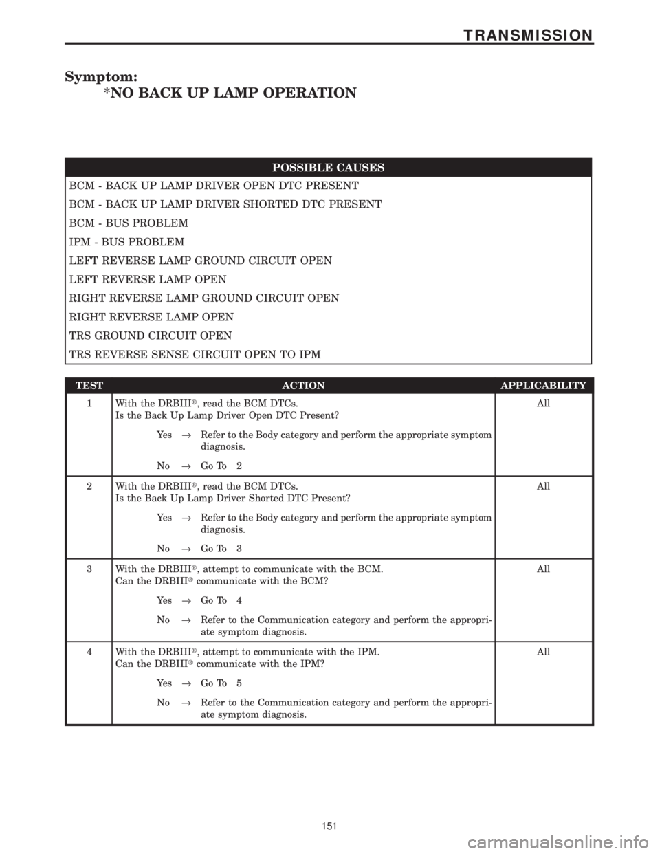
Symptom:
*NO BACK UP LAMP OPERATION
POSSIBLE CAUSES
BCM - BACK UP LAMP DRIVER OPEN DTC PRESENT
BCM - BACK UP LAMP DRIVER SHORTED DTC PRESENT
BCM - BUS PROBLEM
IPM - BUS PROBLEM
LEFT REVERSE LAMP GROUND CIRCUIT OPEN
LEFT REVERSE LAMP OPEN
RIGHT REVERSE LAMP GROUND CIRCUIT OPEN
RIGHT REVERSE LAMP OPEN
TRS GROUND CIRCUIT OPEN
TRS REVERSE SENSE CIRCUIT OPEN TO IPM
TEST ACTION APPLICABILITY
1 With the DRBIIIt, read the BCM DTCs.
Is the Back Up Lamp Driver Open DTC Present?All
Ye s®Refer to the Body category and perform the appropriate symptom
diagnosis.
No®Go To 2
2 With the DRBIIIt, read the BCM DTCs.
Is the Back Up Lamp Driver Shorted DTC Present?All
Ye s®Refer to the Body category and perform the appropriate symptom
diagnosis.
No®Go To 3
3 With the DRBIIIt, attempt to communicate with the BCM.
Can the DRBIIItcommunicate with the BCM?All
Ye s®Go To 4
No®Refer to the Communication category and perform the appropri-
ate symptom diagnosis.
4 With the DRBIIIt, attempt to communicate with the IPM.
Can the DRBIIItcommunicate with the IPM?All
Ye s®Go To 5
No®Refer to the Communication category and perform the appropri-
ate symptom diagnosis.
151
TRANSMISSION
Page 4256 of 4284
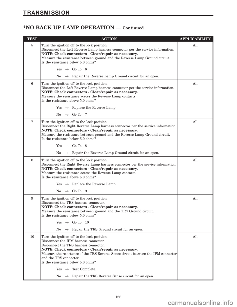
TEST ACTION APPLICABILITY
5 Turn the ignition off to the lock position.
Disconnect the Left Reverse Lamp harness connector per the service information.
NOTE: Check connectors - Clean/repair as necessary.
Measure the resistance between ground and the Reverse Lamp Ground circuit.
Is the resistance below 5.0 ohms?All
Ye s®Go To 6
No®Repair the Reverse Lamp Ground circuit for an open.
6 Turn the ignition off to the lock position.
Disconnect the Left Reverse Lamp harness connector per the service information.
NOTE: Check connectors - Clean/repair as necessary.
Measure the resistance across the Reverse Lamp contacts.
Is the resistance above 5.0 ohms?All
Ye s®Replace the Reverse Lamp.
No®Go To 7
7 Turn the ignition off to the lock position.
Disconnect the Right Reverse Lamp harness connector per the service information.
NOTE: Check connectors - Clean/repair as necessary.
Measure the resistance between ground and the Reverse Lamp Ground circuit.
Is the resistance below 5.0 ohms?All
Ye s®Go To 8
No®Repair the Reverse Lamp Ground circuit for an open.
8 Turn the ignition off to the lock position.
Disconnect the Right Reverse Lamp harness connector per the service information.
NOTE: Check connectors - Clean/repair as necessary.
Measure the resistance across the Reverse Lamp contacts.
Is the resistance above 5.0 ohms?All
Ye s®Replace the Reverse Lamp.
No®Go To 9
9 Turn the ignition off to the lock position.
Disconnect the TRS harness connector.
NOTE: Check connectors - Clean/repair as necessary.
Measure the resistance between ground and the TRS Ground circuit.
Is the resistance below 5.0 ohms?All
Ye s®Go To 10
No®Repair the TRS Ground circuit for an open.
10 Turn the ignition off to the lock position.
Disconnect the IPM harness connector.
Disconnect the TRS harness connector.
NOTE: Check connectors - Clean/repair as necessary.
Measure the resistance of the TRS Reverse Sense circuit between the IPM connector
and the TRS connector.
Is the resistance below 5.0 ohms?All
Ye s®Test Complete.
No®Repair the TRS Reverse Sense circuit for an open.
152
TRANSMISSION
*NO BACK UP LAMP OPERATION ÐContinued
Page 4257 of 4284
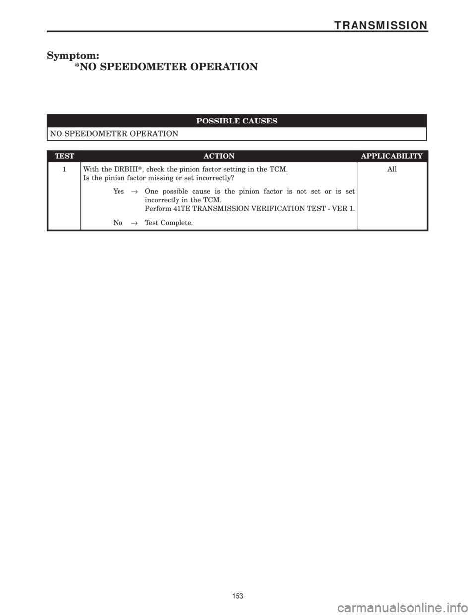
Symptom:
*NO SPEEDOMETER OPERATION
POSSIBLE CAUSES
NO SPEEDOMETER OPERATION
TEST ACTION APPLICABILITY
1 With the DRBIIIt, check the pinion factor setting in the TCM.
Is the pinion factor missing or set incorrectly?All
Ye s®One possible cause is the pinion factor is not set or is set
incorrectly in the TCM.
Perform 41TE TRANSMISSION VERIFICATION TEST - VER 1.
No®Test Complete.
153
TRANSMISSION
Page 4258 of 4284
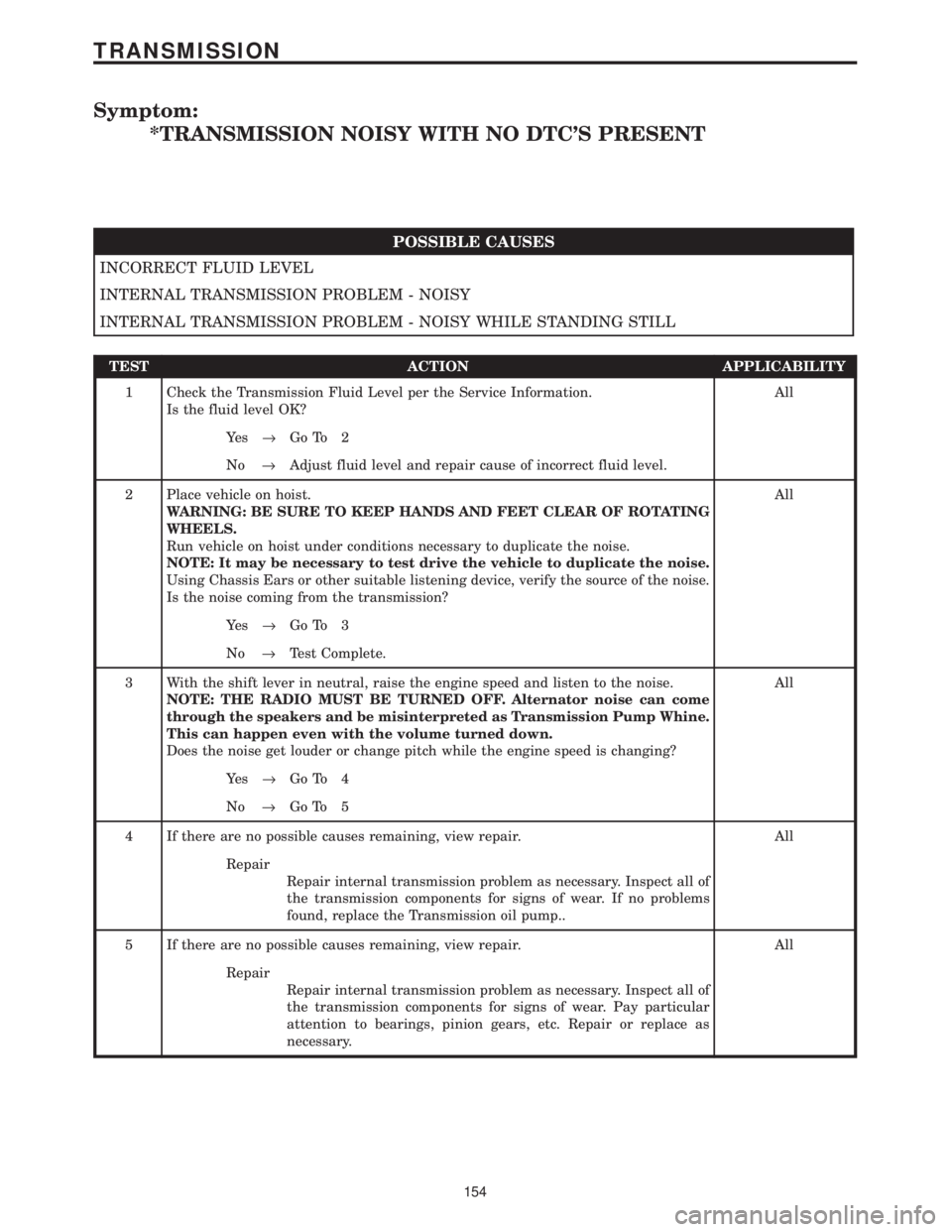
Symptom:
*TRANSMISSION NOISY WITH NO DTC'S PRESENT
POSSIBLE CAUSES
INCORRECT FLUID LEVEL
INTERNAL TRANSMISSION PROBLEM - NOISY
INTERNAL TRANSMISSION PROBLEM - NOISY WHILE STANDING STILL
TEST ACTION APPLICABILITY
1 Check the Transmission Fluid Level per the Service Information.
Is the fluid level OK?All
Ye s®Go To 2
No®Adjust fluid level and repair cause of incorrect fluid level.
2 Place vehicle on hoist.
WARNING: BE SURE TO KEEP HANDS AND FEET CLEAR OF ROTATING
WHEELS.
Run vehicle on hoist under conditions necessary to duplicate the noise.
NOTE: It may be necessary to test drive the vehicle to duplicate the noise.
Using Chassis Ears or other suitable listening device, verify the source of the noise.
Is the noise coming from the transmission?All
Ye s®Go To 3
No®Test Complete.
3 With the shift lever in neutral, raise the engine speed and listen to the noise.
NOTE: THE RADIO MUST BE TURNED OFF. Alternator noise can come
through the speakers and be misinterpreted as Transmission Pump Whine.
This can happen even with the volume turned down.
Does the noise get louder or change pitch while the engine speed is changing?All
Ye s®Go To 4
No®Go To 5
4 If there are no possible causes remaining, view repair. All
Repair
Repair internal transmission problem as necessary. Inspect all of
the transmission components for signs of wear. If no problems
found, replace the Transmission oil pump..
5 If there are no possible causes remaining, view repair. All
Repair
Repair internal transmission problem as necessary. Inspect all of
the transmission components for signs of wear. Pay particular
attention to bearings, pinion gears, etc. Repair or replace as
necessary.
154
TRANSMISSION
Page 4259 of 4284
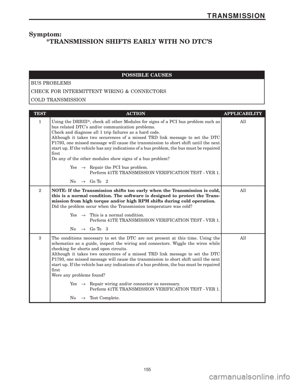
Symptom:
*TRANSMISSION SHIFTS EARLY WITH NO DTC'S
POSSIBLE CAUSES
BUS PROBLEMS
CHECK FOR INTERMITTENT WIRING & CONNECTORS
COLD TRANSMISSION
TEST ACTION APPLICABILITY
1 Using the DRBIIIt, check all other Modules for signs of a PCI bus problem such as
bus related DTC's and/or communication problems.
Check and diagnose all 1 trip failures as a hard code.
Although it takes two occurences of a missed TRD link message to set the DTC
P1793, one missed message will cause the transmission to short shift until the next
start up. If the vehicle has any indications of a bus problem, the bus must be repaired
first
Do any of the other modules show signs of a bus problem?All
Ye s®Repair the PCI bus problem.
Perform 41TE TRANSMISSION VERIFICATION TEST - VER 1.
No®Go To 2
2NOTE: If the Transmission shifts too early when the Transmission is cold,
this is a normal condition. The software is designed to protect the Trans-
mission from high torque and/or high RPM shifts during cold operation.
Did the problem occur when the Transmission temperature was cold?All
Ye s®This is a normal condition.
Perform 41TE TRANSMISSION VERIFICATION TEST - VER 1.
No®Go To 3
3 The conditions necessary to set the DTC are not present at this time. Using the
schematics as a guide, inspect the wiring and connectors. Wiggle the wires while
checking for shorts and open circuits.
Although it takes two occurences of a missed TRD link message to set the DTC
P1793, one missed message will cause the transmission to short shift until the next
start up. If the vehicle has any indications of a bus problem, the bus must be repaired
first
Were any problems found?All
Ye s®Repair wiring and/or connector as necessary.
Perform 41TE TRANSMISSION VERIFICATION TEST - VER 1.
No®Test Complete.
155
TRANSMISSION
Page 4260 of 4284
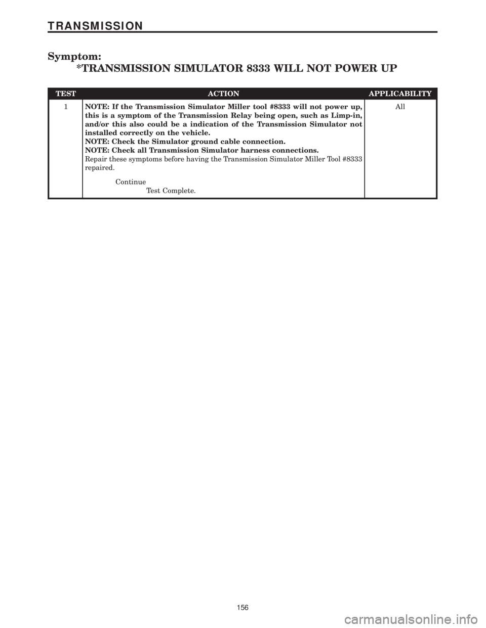
Symptom:
*TRANSMISSION SIMULATOR 8333 WILL NOT POWER UP
TEST ACTION APPLICABILITY
1NOTE: If the Transmission Simulator Miller tool #8333 will not power up,
this is a symptom of the Transmission Relay being open, such as Limp-in,
and/or this also could be a indication of the Transmission Simulator not
installed correctly on the vehicle.
NOTE: Check the Simulator ground cable connection.
NOTE: Check all Transmission Simulator harness connections.
Repair these symptoms before having the Transmission Simulator Miller Tool #8333
repaired.All
Continue
Test Complete.
156
TRANSMISSION