display CHRYSLER VOYAGER 2001 Service Manual
[x] Cancel search | Manufacturer: CHRYSLER, Model Year: 2001, Model line: VOYAGER, Model: CHRYSLER VOYAGER 2001Pages: 4284, PDF Size: 83.53 MB
Page 3918 of 4284

Symptom:
P0401 - EGR SYSTEM FAILURE
When Monitored and Set Condition:
P0401 - EGR SYSTEM FAILURE
When Monitored: With the ignition on and the battery voltage greater than 10.4 volts.
Set Condition: Conditions are met, the EGR is turned off and on momentarily. The
oxygen sensor signal is monitor for changes in its output signal during this test. If no
significant change or too much change is seen, a flag is set.
POSSIBLE CAUSES
INTERMITTENT CONDITION
EGR SOLENOID VACUUM SUPPLY
EGR VALVE OPERATION (CLOSED)
EGR VALVE OPERATION (OPEN)
FUSED IGNITION SWITCH OUTPUT CIRCUIT OPEN
EGR SOLENOID CONTROL CKT SHORTED TO VOLTAGE
EGR SOLENOID CONTROL CKT OPEN
EGR SOLENOID (CLOSED)
EGR SOLENOID CONTROL CKT SHORT TO GND
EGR SOLENOID (OPEN)
PCM
PCM (CLOSED)
TEST ACTION APPLICABILITY
1 Turn the ignition on.
With the DRBIIIt, read DTC's.
Is the Good Trip displayed and equal to zero?All
Ye s®Go To 2
No®Go To 12
2 Start the engine.
Allow the engine to reach operating temperature.
Does the engine run rough or stall at idle?All
Ye s®Go To 3
No®Go To 6
124
DRIVEABILITY - GAS
Page 3922 of 4284

Symptom:
P0403 - EGR SOLENOID CIRCUIT
When Monitored and Set Condition:
P0403 - EGR SOLENOID CIRCUIT
When Monitored: Engine running. Battery voltage greater than 10 volts.
Set Condition: The EGR solenoid control circuit is not in the expected state when
requested to operate by the PCM.
POSSIBLE CAUSES
INTERMITTENT CONDITION
EGR SOLENOID
FUSED IGNITION SWITCH OUTPUT CIRCUIT OPEN
EGR SOLENOID CONTROL CKT SHORTED TO VOLTAGE
EGR SOLENOID CONTROL CKT SHORT TO GND
EGR SOLENOID CONTROL CKT OPEN
PCM
TEST ACTION APPLICABILITY
1 Turn the ignition on.
With the DRBIIIt, read DTC's.
Is the Good Trip displayed and equal to zero?All
Ye s®Go To 2
No®Go To 8
2 Turn the ignition off.
Disconnect the EGR Solenoid harness connector.
Turn the ignition on.
Turn all accessories off.
Using a 12 volt Test Light connected to the Fused Ignition Switch Output circuit,
probe the EGR Solenoid Control circuit.
With the DRB, actuate the EGR solenoid.
Does the 12 volt test light flash on and off?All
Ye s®Inspect the EGR Valve Back Pressure hose and tube for obstruc-
tions or damage. If OK, replace the EGR Solenoid.
Perform POWERTRAIN VERIFICATION TEST VER - 5.
No®Go To 3
128
DRIVEABILITY - GAS
Page 3925 of 4284

Symptom:
P0420-1/1 CATALYTIC CONVERTER EFFICIENCY
When Monitored and Set Condition:
P0420-1/1 CATALYTIC CONVERTER EFFICIENCY
When Monitored: After engine warm up to 70ÉC (158ÉF), 180 seconds of open throttle
operation, at a speed greater than 18 mph and less than 55 mph, with the engine at
1200-1700 rpm and MAP vacuum between 15.0 and 21.0 inches of mercury (Hg).
Set Condition: As catalyst efficiency deteriorates, the switch rate of the downstream O2
sensor approaches that of the upstream O2 sensor. If at any point during the test the
switch ratio reaches a predetermined value a counter is incremented by one.
POSSIBLE CAUSES
INTERMITTENT CONDITION
VISUALLY INSPECT CATALYTIC CONVERTER
EXHAUST LEAK
ENGINE MECHANICAL CONDITION
AGING O2 SENSOR
CATALYTIC CONVERTER
TEST ACTION APPLICABILITY
1NOTE: If a O2 Sensor DTC(s) set along with the Catalytic Converter
Efficiency DTC diagnose the O2 Sensor DTC(s) before continuing.
NOTE: Check for contaminates that may have damaged the O2 Sensor and
Catalytic Converter: contaminated fuel, unapproved silicone, oil and cool-
ant, repair necessary.
Turn the ignition on.
With the DRBIIIt, read DTC's.
Is the Good Trip displayed and equal to zero?All
Ye s®Go To 2
No®Go To 7
2 Inspect the Catalytic Converter for the following damage.
Damage Catalytic Converter, dent and holes.
Severe discoloration caused by overheating the Catalytic Converter.
Catalytic Converter broke internally.
Leaking Catalytic Converter.
Were any problems found?All
Ye s®Replace the Catalytic Converter. Repair the condition that may
have caused the failure.
Perform POWERTRAIN VERIFICATION TEST VER - 5.
No®Go To 3
131
DRIVEABILITY - GAS
Page 3927 of 4284

Symptom:
P0441-EVAP PURGE FLOW MONITOR
When Monitored and Set Condition:
P0441-EVAP PURGE FLOW MONITOR
When Monitored: With engine temperature greater than 71ÉC (160ÉF), fuel control in
closed loop, engine idling for 200 seconds, no low fuel, MAP less than 23.6 inches mercury
and barometric altitude less than 8,000 feet.
Set Condition: After having passed the Leak Detection Pump (LDP) test, no air flow
through the evaporative system is detected by the evap monitor.
POSSIBLE CAUSES
INTERMITTENT CONDITION
EVAP PURGE SOLENOID LEAKS/STUCK OPEN
EVAP PURGE SOLENOID STUCK CLOSED
EVAP PURGE SOLENOID VACUUM SUPPLY
EVAP PURGE HOSE SOLENOID TO CANISTER
EVAP PURGE HOSE CANISTER TO FUEL TANK
EVAP CANISTER
TEST ACTION APPLICABILITY
1 Turn the ignition on.
With the DRBIIIt, read DTC's.
Is the Good Trip Counter displayed and equal to zero?All
Ye s®Go To 2
No®Go To 8
2NOTE: After disconnecting the Evap Purge Solenoid vacuum connections,
inspect the lines and solenoid for any signs of contamination from the EVAP
Canister. This may indicate a faulty rollover valve. Replace/repair as
necessary.
Turn the ignition off.
Disconnect the vacuum hoses at the Evap Purge Solenoid.
Using a hand vacuum pump, apply 10 inches of vacuum to the Evap Purge Solenoid
vacuum source port on the component side.
Does the Evap Purge Solenoid hold vacuum?All
Ye s®Go To 3
No®Replace the Evap Purge Solenoid.
Perform POWERTRAIN VERIFICATION TEST VER - 5.
133
DRIVEABILITY - GAS
Page 3931 of 4284

TEST ACTION APPLICABILITY
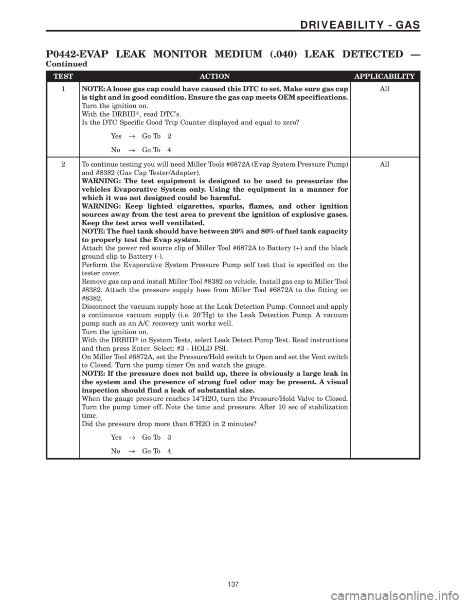
1NOTE: A loose gas cap could have caused this DTC to set. Make sure gas cap
is tight and in good condition. Ensure the gas cap meets OEM specifications.
Turn the ignition on.
With the DRBIIIt, read DTC's.
Is the DTC Specific Good Trip Counter displayed and equal to zero?All
Ye s®Go To 2
No®Go To 4
2 To continue testing you will need Miller Tools #6872A (Evap System Pressure Pump)
and #8382 (Gas Cap Tester/Adapter).
WARNING: The test equipment is designed to be used to pressurize the
vehicles Evaporative System only. Using the equipment in a manner for
which it was not designed could be harmful.
WARNING: Keep lighted cigarettes, sparks, flames, and other ignition
sources away from the test area to prevent the ignition of explosive gases.
Keep the test area well ventilated.
NOTE: The fuel tank should have between 20% and 80% of fuel tank capacity
to properly test the Evap system.
Attach the power red source clip of Miller Tool #6872A to Battery (+) and the black
ground clip to Battery (-).
Perform the Evaporative System Pressure Pump self test that is specified on the
tester cover.
Remove gas cap and install Miller Tool #8382 on vehicle. Install gas cap to Miller Tool
#8382. Attach the pressure supply hose from Miller Tool #6872A to the fitting on
#8382.
Disconnect the vacuum supply hose at the Leak Detection Pump. Connect and apply
a continuous vacuum supply (i.e. 209Hg) to the Leak Detection Pump. A vacuum
pump such as an A/C recovery unit works well.
Turn the ignition on.
With the DRBIIItin System Tests, select Leak Detect Pump Test. Read instructions
and then press Enter. Select: #3 - HOLD PSI.
On Miller Tool #6872A, set the Pressure/Hold switch to Open and set the Vent switch
to Closed. Turn the pump timer On and watch the gauge.
NOTE: If the pressure does not build up, there is obviously a large leak in
the system and the presence of strong fuel odor may be present. A visual
inspection should find a leak of substantial size.
When the gauge pressure reaches 149H2O, turn the Pressure/Hold Valve to Closed.
Turn the pump timer off. Note the time and pressure. After 10 sec of stabilization
time.
Did the pressure drop more than 69H2O in 2 minutes?All
Ye s®Go To 3
No®Go To 4
137
DRIVEABILITY - GAS
P0442-EVAP LEAK MONITOR MEDIUM (.040) LEAK DETECTED Ð
Continued
Page 3933 of 4284

Symptom:
P0443-EVAP PURGE SOLENOID CIRCUIT
When Monitored and Set Condition:
P0443-EVAP PURGE SOLENOID CIRCUIT
When Monitored: The ignition on or engine running. Battery voltage greater than 10
volts.
Set Condition: The PCM will set a trouble code if the actual state of the solenoid does not
match the intended state.
POSSIBLE CAUSES
INTERMITTENT CONDITION
EVAP PURGE SOLENOID CONTROL CIRCUIT OPEN
EVAP PURGE SOLENOID CONTROL CIRCUIT SHORTED TO GROUND
EVAP PURGE SOLENOID SENSE CIRCUIT OPEN
EVAP PURGE SOLENOID SENSE CIRCUIT SHORTED TO GROUND
EVAP PURGE SOLENOID
EVAP PURGE SOLENOID LEAKS/STUCK OPEN
EVAP PURGE SOLENOID STUCK CLOSED
POWERTRAIN CONTROL MODULE
TEST ACTION APPLICABILITY
1 Turn the ignition on.
With the DRBIIIt, read DTC's.
Is the Good Trip Counter displayed and equal to zero for P0443?All
Ye s®Go To 2
No®Go To 10
2 Turn the ignition off.
Disconnect the Evap Purge Solenoid harness connector.
Disconnect the Powertrain Control Module harness connectors.
Measure the resistance of the Evap Purge Solenoid Control circuit from the PCM
harness connector to the Evap Purge Solenoid harness connector.
Is the resistance below 5.0 ohms?All
Ye s®Go To 3
No®Repair the Evap Purge Solenoid Control circuit for an open.
Perform POWERTRAIN VERIFICATION TEST VER - 5.
139
DRIVEABILITY - GAS
Page 3936 of 4284

Symptom:
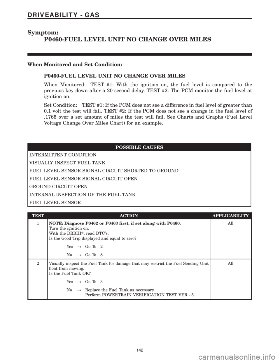
P0460-FUEL LEVEL UNIT NO CHANGE OVER MILES
When Monitored and Set Condition:
P0460-FUEL LEVEL UNIT NO CHANGE OVER MILES
When Monitored: TEST #1: With the ignition on, the fuel level is compared to the
previuos key down after a 20 second delay. TEST #2: The PCM monitor the fuel level at
ignition on.
Set Condition: TEST #1: If the PCM does not see a difference in fuel level of greater than
0.1 volt the test will fail. TEST #2: If the PCM does not see a change in the fuel level of
.1765 over a set amount of miles the test will fail. See Charts and Graphs (Fuel Level
Voltage Change Over Miles Chart) for an example.
POSSIBLE CAUSES
INTERMITTENT CONDITION
VISUALLY INSPECT FUEL TANK
FUEL LEVEL SENSOR SIGNAL CIRCUIT SHORTED TO GROUND
FUEL LEVEL SENSOR SIGNAL CIRCUIT OPEN
GROUND CIRCUIT OPEN
INTERNAL INSPECTION OF THE FUEL TANK
FUEL LEVEL SENSOR
TEST ACTION APPLICABILITY
1NOTE: Diagnose P0462 or P0463 first, if set along with P0460.
Turn the ignition on.
With the DRBIIIt, read DTC's.
Is the Good Trip displayed and equal to zero?All
Ye s®Go To 2
No®Go To 8
2 Visually inspect the Fuel Tank for damage that may restrict the Fuel Sending Unit
float from moving.
Is the Fuel Tank OK?All
Ye s®Go To 3
No®Replace the Fuel Tank as necessary.
Perform POWERTRAIN VERIFICATION TEST VER - 5.
142
DRIVEABILITY - GAS
Page 3939 of 4284

Symptom List:
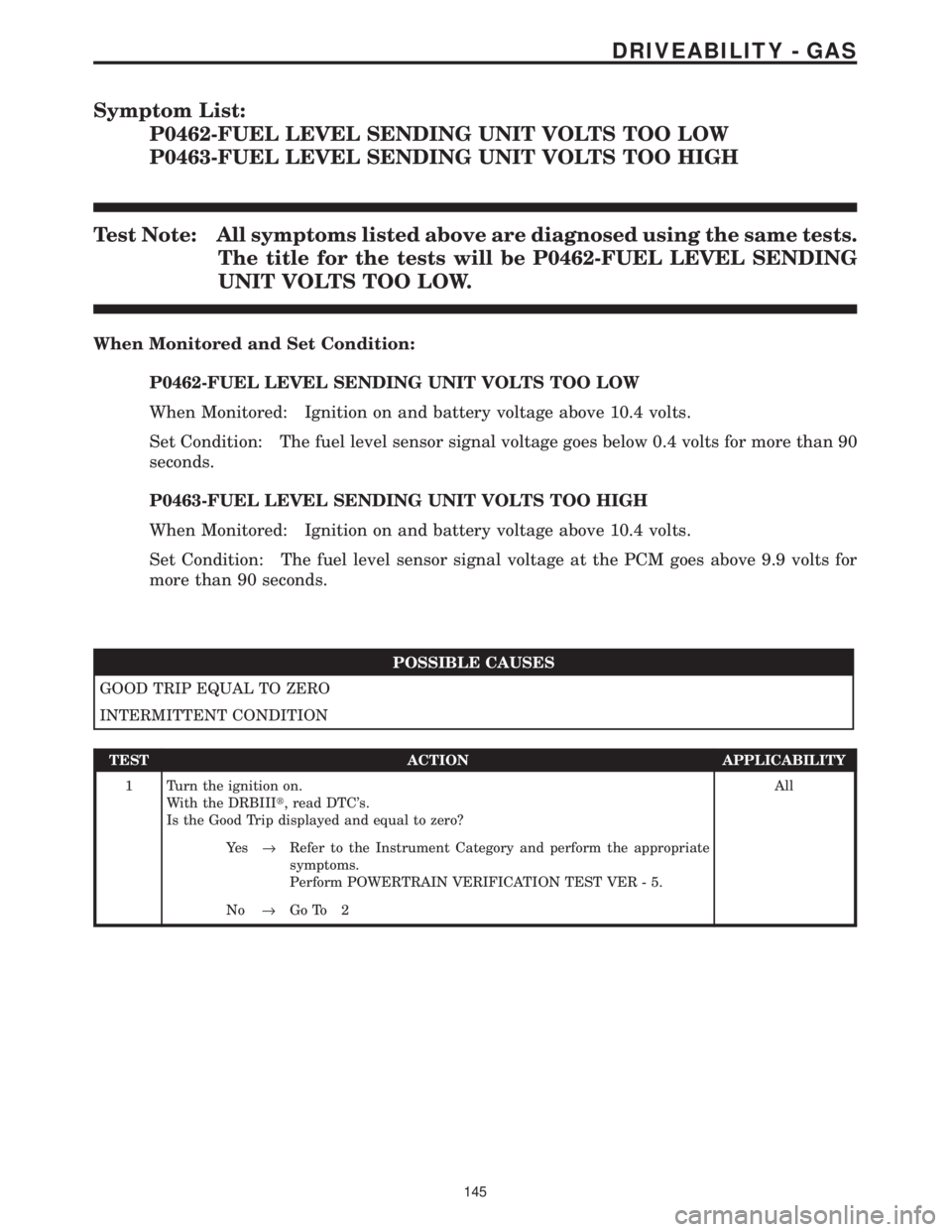
P0462-FUEL LEVEL SENDING UNIT VOLTS TOO LOW
P0463-FUEL LEVEL SENDING UNIT VOLTS TOO HIGH
Test Note: All symptoms listed above are diagnosed using the same tests.
The title for the tests will be P0462-FUEL LEVEL SENDING
UNIT VOLTS TOO LOW.
When Monitored and Set Condition:
P0462-FUEL LEVEL SENDING UNIT VOLTS TOO LOW
When Monitored: Ignition on and battery voltage above 10.4 volts.
Set Condition: The fuel level sensor signal voltage goes below 0.4 volts for more than 90
seconds.
P0463-FUEL LEVEL SENDING UNIT VOLTS TOO HIGH
When Monitored: Ignition on and battery voltage above 10.4 volts.
Set Condition: The fuel level sensor signal voltage at the PCM goes above 9.9 volts for
more than 90 seconds.
POSSIBLE CAUSES
GOOD TRIP EQUAL TO ZERO
INTERMITTENT CONDITION
TEST ACTION APPLICABILITY
1 Turn the ignition on.
With the DRBIIIt, read DTC's.
Is the Good Trip displayed and equal to zero?All
Ye s®Refer to the Instrument Category and perform the appropriate
symptoms.
Perform POWERTRAIN VERIFICATION TEST VER - 5.
No®Go To 2
145
DRIVEABILITY - GAS
Page 3941 of 4284

Symptom:
P0500-NO VEHICLE SPEED SIGNAL (3SP AUTO AND MANUAL
TRANSMISSIONS)
When Monitored and Set Condition:
P0500-NO VEHICLE SPEED SIGNAL (3SP AUTO AND MANUAL TRANSMIS-
SIONS)
When Monitored: With the engine running, transmission not in park or neutral, brakes
not applied, and engine rpm greater than 1800.
Set Condition: This code will set if no vehicle speed signal is received from the Vehicle
Speed Sensor for more than 7.2 seconds for 2 consecutive trips.
POSSIBLE CAUSES
INTERMITTENT CONDITION
8 VOLT SUPPLY CIRCUIT OPEN
VEHICLE SPEED SENSOR SIGNAL CIRCUIT SHORTED TO GROUND
VEHICLE SPEED SENSOR SIGNAL CIRCUIT OPEN
PCM VSS SIGNAL
SENSOR GROUND CIRCUIT OPEN
VEHICLE SPEED SENSOR
TEST ACTION APPLICABILITY
1 Raise the drive wheels off the ground.
WARNING: BE SURE TO KEEP HANDS AND FEET CLEAR OF ROTATING
WHEELS.
Start the engine.
With the DRBIIIt, monitor the Vehicle Speed Sensor
Place the transmission in any forward gear.
Allow the wheels to rotate.
Does the DRBIIItdisplay vehicle speed above 0 MPH/KMH?All
Ye s®Go To 2
No®Go To 3
147
DRIVEABILITY - GAS
Page 3944 of 4284

Symptom:
P0500-NO VEHICLE SPEED SIGNAL (4SP AUTO TRANS)
When Monitored and Set Condition:
P0500-NO VEHICLE SPEED SIGNAL (4SP AUTO TRANS)
When Monitored: With the engine running, transmission not in park or neutral, brakes
not applied, and engine rpm greater than 1800.
Set Condition: This code will set if no vehicle speed signal is received from the TCM
(transmission control module) for more than 7.2 seconds for 2 consecutive trips.
POSSIBLE CAUSES
INTERMITTENT CONDITION
VEHICLE SPEED SENSOR SIGNAL SHORTED VOLTAGE
VSS SIGNAL FROM TCM
VEHICLE SPEED SENSOR SIGNAL SHORTED TO GROUND
VEHICLE SPEED SENSOR SIGNAL OPEN
PCM VSS SIGNAL
TEST ACTION APPLICABILITY
1 Turn the ignition on.
With the DRBIIIt, read DTC's.
Is the Good Trip displayed and equal to zero?All
Ye s®Go To 2
No®Go To 7
2 Turn the ignition off.
Disconnect the TCM harness connector.
Turn the ignition on.
Measure the voltage of the VSS Signal circuit in the TCM harness connector.
Is the voltage above 6.0 volts?All
Ye s®Repair the Vehicle Speed Sensor Signal circuit for a short to
voltage.
Perform POWERTRAIN VERIFICATION TEST VER - 5.
No®Go To 3
150
DRIVEABILITY - GAS