display CHRYSLER VOYAGER 2001 Service Manual
[x] Cancel search | Manufacturer: CHRYSLER, Model Year: 2001, Model line: VOYAGER, Model: CHRYSLER VOYAGER 2001Pages: 4284, PDF Size: 83.53 MB
Page 3635 of 4284
MANUAL TEMPERATURE CONTROL
The front blower speed must be set to High and
the evaporator temperature sensor must be greater
than 55É F or the test will fail immediately. The test
is activated by depressing the A/C and PWR buttons
simultaneously and holding them depressed for no
less than five seconds. The PWR and A/C LEDs will
blink on and off until the test is complete. If the
LEDs stop blinking after two minutes, then the cool
down test has been completed successfully. If the two
minutes expire without the evaporator temperature
reaching 20É F less than the outside air temperature,
then the cool down test has been failed and further
A/C system diagnosis is required. If the test is failed,
the LEDs will continue to blink across ignition cycles
until the vehicle has been driven for greater than (3
miles).
AUTOMATIC TEMPERATURE CONTROL
The outside air temperature shown in the ATC dis-
play must not be lower than 53É F or the test will not
begin. The ambient air temperature in the room
where the vehicle will be tested must be a minimum
of 21É C (70ÉF) for this test.The test is activated by
depressing the A/C and PWR buttons simultaneously
and holding them depressed for no less than four sec-
onds. The snowflake icon and the DELAY text in the
ATC display will blink on and off alternately until
the test is complete. If the snowflake icon and the
DELAY text stop blinking after two minutes, then
the cool down test has been completed successfully. If
the two minutes expire without the evaporator tem-
perature reaching 20É F less than the evaporator ini-
tial temperature, then the cool down test has been
failed and further A/C system diagnosis is required.
If the test is failed, the snowflake icon and the
DELAY text will continue to blink across ignition
cycles until the vehicle has been driven for greater
than (3 miles).
DIAGNOSIS AND TESTING - A/C
PERFORMANCE TEST
An air conditioning performance test is the best
way to determine whether the system is performing
up to standard. This test also provides valuable clues
as to the possible cause of trouble with the air con-
ditioning system. The ambient air temperature in the
location where the vehicle will be tested must be a
minimum of 21É C (70ÉF) for this test.
WARNING: REFER TO THE APPLICABLE WARN-
INGS AND CAUTIONS FOR THIS SYSTEM BEFORE
PERFORMING THE FOLLOWING OPERATION.(Refer to 24 - HEATING & AIR CONDITIONING/
PLUMBING - FRONT - WARNING - A/C PLUMBING)
and (Refer to 24 - HEATING & AIR CONDITIONING/
PLUMBING - FRONT - CAUTION - A/C PLUMBING).
NOTE: When connecting the service equipment
coupling to the line fitting, verify that the valve of
the coupling is fully closed. This will reduce the
amount of effort required to make the connection.
(1) Connect a tachometer to monitor the engine
speed.
(2) Remove the caps from the refrigerant system
service ports and attach a manifold gauge set to
monitor the refrigerant system pressures.
(3) Set the heater-air conditioner controls so that
the compressor is engaged, the air within the vehicle
is being recirculated, the output air is directed
through the panel outlets, the temperature control is
in the full cool position, and the blower motor is oper-
ating at its highest speed.
(4) Start the engine and allow the engine to oper-
ate for about five minutes or until it reaches normal
operating temperature. Then hold the engine speed
at 1000 rpm with the compressor clutch engaged. If
the compressor clutch does not engage, proceed with
diagnosis of the compressor clutch coil. (Refer to 24 -
HEATING & AIR CONDITIONING/CONTROLS -
FRONT/COMPRESSOR CLUTCH COIL - DIAGNO-
SIS AND TESTING).
(5) Close all the vehicle windows and doors.
(6) Insert a thermometer in the left center panel
outlet and operate the engine for five minutes.
(7) With the compressor clutch engaged, record the
left center panel outlet discharge air temperature,
the discharge pressure (high side service port), and
the suction pressure (low side service port). The com-
pressor clutch may cycle, depending upon the ambi-
ent temperature and humidity. If the clutch cycles,
use the readings obtained before the clutch disen-
gaged.
(8) Compare the discharge air temperature read-
ing to the Performance Temperature and Pressure
chart. If the temperature reading is high, check the
refrigerant system for leaks and proper refrigerant
charge level. (Refer to 24 - HEATING & AIR CONDI-
TIONING/PLUMBING - FRONT/REFRIGERANT -
DIAGNOSIS AND TESTING - REFRIGERANT SYS-
TEM LEAKS) and (Refer to 24 - HEATING & AIR
CONDITIONING/PLUMBING - FRONT/REFRIGER-
ANT - DIAGNOSIS AND TESTING - REFRIGER-
ANT SYSTEM CHARGE LEVEL).
RSHEATING & AIR CONDITIONING24-5
HEATING & AIR CONDITIONING (Continued)
Page 3759 of 4284
speed above the maximum threshold (2000 rpm), the
PCM will not store a DTC.
There are several operating conditions for which
the PCM monitors and sets DTC's. Refer to Moni-
tored Systems, Components, and Non-Monitored Cir-
cuits in this section.
NOTE: Various diagnostic procedures may actually
cause a diagnostic monitor to set a DTC. For
instance, pulling a spark plug wire to perform a
spark test may set the misfire code. When a repair
is completed and verified, use the DRBIIITscan tool
to erase all DTC's and extinguish the MIL.
Technicians can display stored DTC's. Refer to
Diagnostic Trouble Codes in this section. For DTC
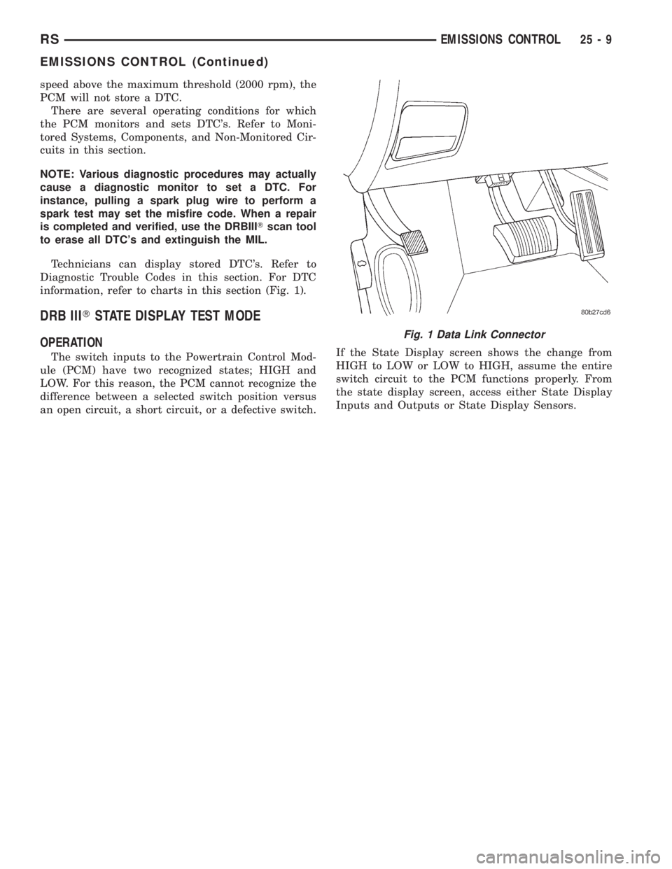
information, refer to charts in this section (Fig. 1).
DRB IIITSTATE DISPLAY TEST MODE
OPERATION
The switch inputs to the Powertrain Control Mod-
ule (PCM) have two recognized states; HIGH and
LOW. For this reason, the PCM cannot recognize the
difference between a selected switch position versus
an open circuit, a short circuit, or a defective switch.If the State Display screen shows the change from
HIGH to LOW or LOW to HIGH, assume the entire
switch circuit to the PCM functions properly. From
the state display screen, access either State Display
Inputs and Outputs or State Display Sensors.
Fig. 1 Data Link Connector
RSEMISSIONS CONTROL25-9
EMISSIONS CONTROL (Continued)
Page 3774 of 4284
The Task Manager Screen shows both a Requested
MIL state and an Actual MIL state. When the MIL is
illuminated upon completion of a test for a third trip,
the Requested MIL state changes to OFF. However,
the MIL remains illuminated until the next key
cycle. (On some vehicles, the MIL will actually turn
OFF during the third key cycle) During the key cycle
for the third good trip, the Requested MIL state is
OFF, while the Actual MILL state is ON. After the
next key cycle, the MIL is not illuminated and both
MIL states read OFF.
Diagnostic Trouble Codes (DTCs)
With OBD II, different DTC faults have different
priorities according to regulations. As a result, the
priorities determine MIL illumination and DTC era-
sure. DTCs are entered according to individual prior-
ity. DTCs with a higher priority overwrite lower
priority DTCs.
Priorities
²Priority 0 ÐNon-emissions related trouble codes
²Priority 1 Ð One trip failure of a two trip fault
for non-fuel system and non-misfire.
²Priority 2 Ð One trip failure of a two trip fault
for fuel system (rich/lean) or misfire.
²Priority3ÐTwotrip failure for a non-fuel sys-
tem and non-misfire or matured one trip comprehen-
sive component fault.
²Priority4ÐTwotrip failure or matured fault
for fuel system (rich/lean) and misfire or one trip cat-
alyst damaging misfire.
Non-emissions related failures have no priority.
One trip failures of two trip faults have low priority.
Two trip failures or matured faults have higher pri-
ority. One and two trip failures of fuel system and
misfire monitor take precedence over non-fuel system
and non-misfire failures.
DTC Self Erasure
With one trip components or systems, the MIL is
illuminated upon test failure and DTCs are stored.
Two trip monitors are components requiring failure
in two consecutive trips for MIL illumination. Upon
failure of the first test, the Task Manager enters a
maturing code. If the component fails the test for a
second time the code matures and a DTC is set.
After three good trips the MIL is extinguished and
the Task Manager automatically switches the trip
counter to a warm-up cycle counter. DTCs are auto-
matically erased following 40 warm-up cycles if the
component does not fail again.
For misfire and fuel system monitors, the compo-
nent must pass the test under a Similar Conditions
Window in order to record a good trip. A Similar Con-
ditions Window is when engine RPM is within6375RPM and load is within610% of when the fault
occurred.
NOTE: It is important to understand that a compo-
nent does not have to fail under a similar window of
operation to mature. It must pass the test under a
Similar Conditions Window when it failed to record
a Good Trip for DTC erasure for misfire and fuel
system monitors.
DTCs can be erased anytime with a DRBIIIt.
Erasing the DTC with the DRBIIIterases all OBD II
information. The DRBIIItautomatically displays a
warning that erasing the DTC will also erase all
OBD II monitor data. This includes all counter infor-
mation for warm-up cycles, trips and Freeze Frame.
Trip Indicator
TheTripis essential for running monitors and
extinguishing the MIL. In OBD II terms, a trip is a
set of vehicle operating conditions that must be met
for a specific monitor to run. All trips begin with a
key cycle.
Good Trip
The Good Trip counters are as follows:
²Global Good Trip
²Fuel System Good Trip
²Misfire Good Trip
²Alternate Good Trip (appears as a Global Good
Trip on DRBIIIt)
²Comprehensive Components
²Major Monitor
²Warm-Up Cycles
Global Good Trip
To increment a Global Good Trip, the Oxygen sen-
sor and Catalyst efficiency monitors must have run
and passed.
Fuel System Good Trip
To count a good trip (three required) and turn off
the MIL, the following conditions must occur:
²Engine in closed loop
²Operating in Similar Conditions Window
²Short Term multiplied by Long Term less than
threshold
²Less than threshold for a predetermined time
If all of the previous criteria are met, the PCM will
count a good trip (three required) and turn off the
MIL.
Misfire Good Trip
If the following conditions are met the PCM will
count one good trip (three required) in order to turn
off the MIL:
²Operating in Similar Condition Window
²1000 engine revolutions with no misfire
Alternate Good Trip
Alternate Good Trips are used in place of Global
Good Trips for Comprehensive Components and
25 - 24 ON-BOARD DIAGNOSTICSRS
TASK MANAGER (Continued)
Page 3775 of 4284
Major Monitors. If the Task Manager cannot run a
Global Good Trip because a component fault is stop-
ping the monitor from running, it will attempt to
count an Alternate Good Trip.
The Task Manager counts an Alternate Good Trip
for Comprehensive components when the following
conditions are met:
²Two minutes of engine run time
²No other faults occur
The Task Manager counts an Alternate Good Trip
for a Major Monitor when the monitor runs and
passes. Only the Major Monitor that failed needs to
pass to count an Alternate Good Trip.
Warm-Up Cycles
Once the MIL has been extinguished by the Good
Trip Counter, the PCM automatically switches to a
Warm-Up Cycle Counter that can be viewed on the
DRBIIIt. Warm-Up Cycles are used to erase DTCs
and Freeze Frames. Forty Warm-Up cycles must
occur in order for the PCM to self-erase a DTC and
Freeze Frame. A Warm-Up Cycle is defined as fol-
lows:
²Engine coolant temperature must start below
and rise above 160É F
²Engine coolant temperature must rise by 40É F
²No further faults occur
Freeze Frame Data Storage
Once a failure occurs, the Task Manager records
several engine operating conditions and stores it in a
Freeze Frame. The Freeze Frame is considered one
frame of information taken by an on-board data
recorder. When a fault occurs, the PCM stores the
input data from various sensors so that technicians
can determine under what vehicle operating condi-
tions the failure occurred.
The data stored in Freeze Frame is usually
recorded when a system fails the first time for two
trip faults. Freeze Frame data will only be overwrit-
ten by a different fault with a higher priority.
CAUTION: Erasing DTCs, either with the DRBIIIT;or
by disconnecting the battery, also clears all Freeze
Frame data.
Similar Conditions Window
The Similar Conditions Window displays informa-
tion about engine operation during a monitor. Abso-
lute MAP (engine load) and Engine RPM are stored
in this window when a failure occurs. There are two
different Similar conditions Windows: Fuel System
and Misfire.
FUEL SYSTEM
²Fuel System Similar Conditions WindowÐ
An indicator that 'Absolute MAP When Fuel Sys Fail'
and 'RPM When Fuel Sys Failed' are all in the samerange when the failure occurred. Indicated by switch-
ing from 'NO' to 'YES'.
²Absolute MAP When Fuel Sys FailÐ The
stored MAP reading at the time of failure. Informs
the user at what engine load the failure occurred.
²Absolute MAPÐ A live reading of engine load
to aid the user in accessing the Similar Conditions
Window.
²RPM When Fuel Sys FailÐ The stored RPM
reading at the time of failure. Informs the user at
what engine RPM the failure occurred.
²Engine RPMÐ A live reading of engine RPM
to aid the user in accessing the Similar Conditions
Window.
²Adaptive Memory FactorÐ The PCM utilizes
both Short Term Compensation and Long Term Adap-
tive to calculate the Adaptive Memory Factor for
total fuel correction.
²Upstream O2S VoltsÐ A live reading of the
Oxygen Sensor to indicate its performance. For
example, stuck lean, stuck rich, etc.
²SCW Time in Window (Similar Conditions
Window Time in Window)Ð A timer used by the
PCM that indicates that, after all Similar Conditions
have been met, if there has been enough good engine
running time in the SCW without failure detected.
This timer is used to increment a Good Trip.
²Fuel System Good Trip CounterÐATrip
Counter used to turn OFF the MIL for Fuel System
DTCs. To increment a Fuel System Good Trip, the
engine must be in the Similar Conditions Window,
Adaptive Memory Factor must be less than cali-
brated threshold and the Adaptive Memory Factor
must stay below that threshold for a calibrated
amount of time.
²Test Done This TripÐ Indicates that the
monitor has already been run and completed during
the current trip.
MISFIRE
²Same Misfire Warm-Up StateÐ Indicates if
the misfire occurred when the engine was warmed up
(above 160É F).
²In Similar Misfire WindowÐ An indicator
that 'Absolute MAP When Misfire Occurred' and
'RPM When Misfire Occurred' are all in the same
range when the failure occurred. Indicated by switch-
ing from 'NO' to 'YES'.
²Absolute MAP When Misfire OccurredÐ
The stored MAP reading at the time of failure.
Informs the user at what engine load the failure
occurred.
²Absolute MAPÐ A live reading of engine load
to aid the user in accessing the Similar Conditions
Window.
RSON-BOARD DIAGNOSTICS25-25
TASK MANAGER (Continued)
Page 3777 of 4284

EMISSIONS CONTROL 2.5L TURBO DIESEL
TABLE OF CONTENTS
page page
EMISSIONS CONTROL 2.5L TURBO DIESEL
DESCRIPTION............................1
SPECIFICATIONS.........................2EXHAUST GAS RECIRCULATION.............3
ON-BOARD DIAGNOSTICS..................6
EMISSIONS CONTROL 2.5L
TURBO DIESEL
DESCRIPTION
The 2.5L diesel Engine Control Module (ECM) con-
trols many different circuits in the fuel injection
pump and engine systems. If the ECM senses a prob-
lem with a monitored circuit that indicates an actual
problem, a Diagnostic Trouble Code (DTC) will be
stored in the ECM's memory, and eventually may
illuminate the MIL (Malfunction Indicator Lamp)
constantly while the key is on. If the problem is
repaired, or is intermittent, the ECM will erase the
DTC after 40 warm-up cycles without the the fault
detected. A warm-up cycle consists of starting the
vehicle when the engine is cold, then the engine is
warmed up to a certain temperature, and finally, the
engine temperature falls to a normal operating tem-
perature, then the key is turned off.
Certain criteria must be met for a DTC to be
entered into ECM memory. The criteria may be a
specific range of engine rpm, engine or fuel tempera-
ture and/or input voltage to the ECM. A DTC indi-
cates that the ECM has identified an abnormal
signal in a circuit or the system.
There are several operating conditions that the
ECM does not monitor and set a DTC for. Refer to
the following Monitored Circuits and Non±Monitored
Circuits in this section.
ECM MONITORED SYSTEMS
The ECM can detect certain problems in the elec-
trical system.
Open or Shorted Circuit± The ECM will not
distinguish between an open or a short to ground,
however the ECM can determine if there is excessive
current on a circuit, such as a short to voltage or a
decrease in component resistance.
Output Device Current Flow± The ECM senses
whether the output devices are electrically connected.
If there is a problem with the circuit, the ECM
senses whether the circuit is open, shorted to ground
(±), or shorted to (+) voltage.Fuel Pressure:Fuel pressure is controlled by the
fuel injection pump and fuel pressure solenoid. The
ECM uses a fuel pressure sensor to determine if a
fuel pressure problem exists.
Fuel Injector Malfunctions:The ECM can deter-
mine if a fuel injector has an electrical problem. The
fuel injectors on the diesel engine arecontrolledby
the ECM.
ECM NON±MONITORED SYSTEMS
The ECM does not monitor the following circuits,
systems or conditions that could have malfunctions
that result in driveability problems. A DTC will not
be displayed for these conditions.
Cylinder Compression:The ECM cannot detect
uneven, low, or high engine cylinder compression.
Exhaust System:The ECM cannot detect a
plugged, restricted or leaking exhaust system.
Vacuum Assist:Leaks or restrictions in the vac-
uum circuits of the Exhaust Gas Recirculation Sys-
tem (EGR) are not monitored by the ECM.
ECM System Ground:The ECM cannot deter-
mine a poor system ground. However, a DTC may be
generated as a result of this condition.
ECM/PCM Connector Engagement:The ECM
cannot determine spread or damaged connector pins.
However, a DTC may be generated as a result of this
condition.
HIGH AND LOW LIMITS
The ECM compares input signals from each input
device. It has high and low limits that are pro-
grammed into it for that device. If the inputs are not
within specifications and other DTC criteria are met,
a DTC will be stored in memory. Other DTC criteria
might include engine rpm limits or input voltages
from other sensors or switches. The other inputs
might have to be sensed by the ECM when it senses
a high or low input voltage from the control system
device in question.
RGEMISSIONS CONTROL 2.5L TURBO DIESEL25a-1
Page 3782 of 4284
ON-BOARD DIAGNOSTICS
TABLE OF CONTENTS
page
ON-BOARD DIAGNOSTICS
DESCRIPTION............................6
ON-BOARD DIAGNOSTICS
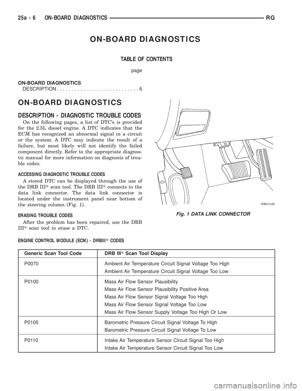
DESCRIPTION - DIAGNOSTIC TROUBLE CODES
On the following pages, a list of DTC's is provided
for the 2.5L diesel engine. A DTC indicates that the
ECM has recognized an abnormal signal in a circuit
or the system. A DTC may indicate the result of a
failure, but most likely will not identify the failed
component directly. Refer to the appropriate diagnos-
tic manual for more information on diagnosis of trou-
ble codes.
ACCESSING DIAGNOSTIC TROUBLE CODES
A stored DTC can be displayed through the use of
the DRB IIItscan tool. The DRB IIItconnects to the
data link connector. The data link connector is
located under the instrument panel near bottom of
the steering column (Fig. 1).
ERASING TROUBLE CODES
After the problem has been repaired, use the DRB
IIItscan tool to erase a DTC.
ENGINE CONTROL MODULE (ECM) - DRBIIITCODES
Generic Scan Tool Code DRB IIITScan Tool Display
P0070 Ambient Air Temperature Circuit Signal Voltage Too High
Ambient Air Temperature Circuit Signal Voltage Too Low
P0100 Mass Air Flow Sensor Plausibility
Mass Air Flow Sensor Plausibility Positive Area
Mass Air Flow Sensor Signal Voltage Too High
Mass Air Flow Sensor Signal Voltage Too Low
Mass Air Flow Sensor Supply Voltage Too High Or Low
P0105 Barometric Pressure Circuit Signal Voltage To High
Barometric Pressure Circuit Signal Voltage To Low
P0110 Intake Air Temperature Sensor Circuit Signal Too High
Intake Air Temperature Sensor Circuit Signal Too Low
Fig. 1 DATA LINK CONNECTOR
25a - 6 ON-BOARD DIAGNOSTICSRG
Page 3783 of 4284

Generic Scan Tool Code DRB IIITScan Tool Display
P0115 Engine Coolant Temperature Sensor Circuit Engine Is Cold Too Long
Engine Coolant Temperature Sensor Circuit Voltage To Low
Engine Coolant Temperature Sensor Circuit Voltage To High
P0190 Fuel Pressure Sensor Circuit MALF Signal Voltage Too High
Fuel Pressure Sensor Circuit MALF Signal Voltage Too Low
P0195 Oil Temperature Sensor Circuit MALF Signal Voltage Too High
Oil Temperature Sensor Circuit MALF Signal Voltage Too Low
P0201 Cylinder 1 Injector Circuit Current Decrease
Cylinder 1 Injector Circuit Load Drop
Cylinder 1 Injector Circuit Overcurrent High Side
Cylinder 1 Injector Circuit Overcurrent Low Side
P0202 Cylinder 2 Injector Circuit Current Decrease
Cylinder 2 Injector Circuit Load Drop
Cylinder 2 Injector Circuit Overcurrent High Side
Cylinder 2 Injector Circuit Overcurrent Low Side
P0203 Cylinder 3 Injector Circuit Current Decrease
Cylinder 3 Injector Circuit Load Drop
Cylinder 3 Injector Circuit Overcurrent High Side
Cylinder 3 Injector Circuit Overcurrent Low Side
P0204 Cylinder 4 Injector Circuit Current Decrease
Cylinder 4 Injector Circuit Load Drop
Cylinder 4 Injector Circuit Overcurrent High Side
Cylinder 4 Injector Circuit Overcurrent Low Side
P0235 Boost Pressure Sensor Plausibility
Boost Pressure Sensor Signal Voltage Too Low
Boost Pressure Sensor Signal Voltage Too High
Boost Pressure Sensor Signal Voltage Too High Or Low
P0335 CKP Position Sensor Circuit Dynamic Plausibility
CKP Position Sensor Circuit Overspeed Recognition
CKP Position Sensor Circuit Static Plausibility
P0340 CMP Position Sensor Circuit CMP/CKP Sync. Failure
CMP Position Sensor Circuit Dynamic Plausibility
CMP Position Sensor Circuit Fuel Shut-Off Activated
CMP Position Sensor Circuit Signal Frequency Too High
CMP Position Sensor Circuit Static Plausibility
P0380 Glow Plug Circuit A Open Circuit
Glow Plug Circuit A Short Circuit
RGON-BOARD DIAGNOSTICS25a-7
ON-BOARD DIAGNOSTICS (Continued)
Page 3784 of 4284
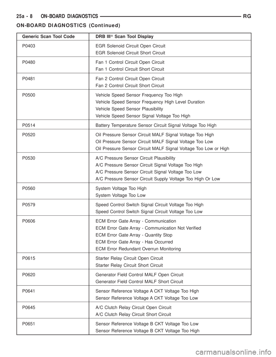
Generic Scan Tool Code DRB IIITScan Tool Display
P0403 EGR Solenoid Circuit Open Circuit
EGR Solenoid Circuit Short Circuit
P0480 Fan 1 Control Circuit Open Circuit
Fan 1 Control Circuit Short Circuit
P0481 Fan 2 Control Circuit Open Circuit
Fan 2 Control Circuit Short Circuit
P0500 Vehicle Speed Sensor Frequency Too High
Vehicle Speed Sensor Frequency High Level Duration
Vehicle Speed Sensor Plausibility
Vehicle Speed Sensor Signal Voltage Too High
P0514 Battery Temperature Sensor Circuit Signal Voltage Too High
P0520 Oil Pressure Sensor Circuit MALF Signal Voltage Too High
Oil Pressure Sensor Circuit MALF Signal Voltage Too Low
Oil Pressure Sensor Circuit MALF Signal Voltage Too Low or High
P0530 A/C Pressure Sensor Circuit Plausibility
A/C Pressure Sensor Circuit Signal Voltage Too High
A/C Pressure Sensor Circuit Signal Voltage Too Low
A/C Pressure Sensor Circuit Supply Voltage Too High Or Low
P0560 System Voltage Too High
System Voltage Too Low
P0579 Speed Control Switch Signal Circuit Voltage Too High
Speed Control Switch Signal Circuit Voltage Too Low
P0606 ECM Error Gate Array - Communication
ECM Error Gate Array - Communication Not Verified
ECM Error Gate Array - Quantity Stop
ECM Error Gate Array - Has Occurred
ECM Error Redundant Overrun Monitoring
P0615 Starter Relay Circuit Open Circuit
Starter Relay Circuit Short Circuit
P0620 Generator Field Control MALF Open Circuit
Generator Field Control MALF Short Circuit
P0641 Sensor Reference Voltage A CKT Voltage Too High
Sensor Reference Voltage A CKT Voltage Too Low
P0645 A/C Clutch Relay Circuit Open Circuit
A/C Clutch Relay Circuit Short Circuit
P0651 Sensor Reference Voltage B CKT Voltage Too Low
Sensor Reference Voltage B CKT Voltage Too High
25a - 8 ON-BOARD DIAGNOSTICSRG
ON-BOARD DIAGNOSTICS (Continued)
Page 3785 of 4284
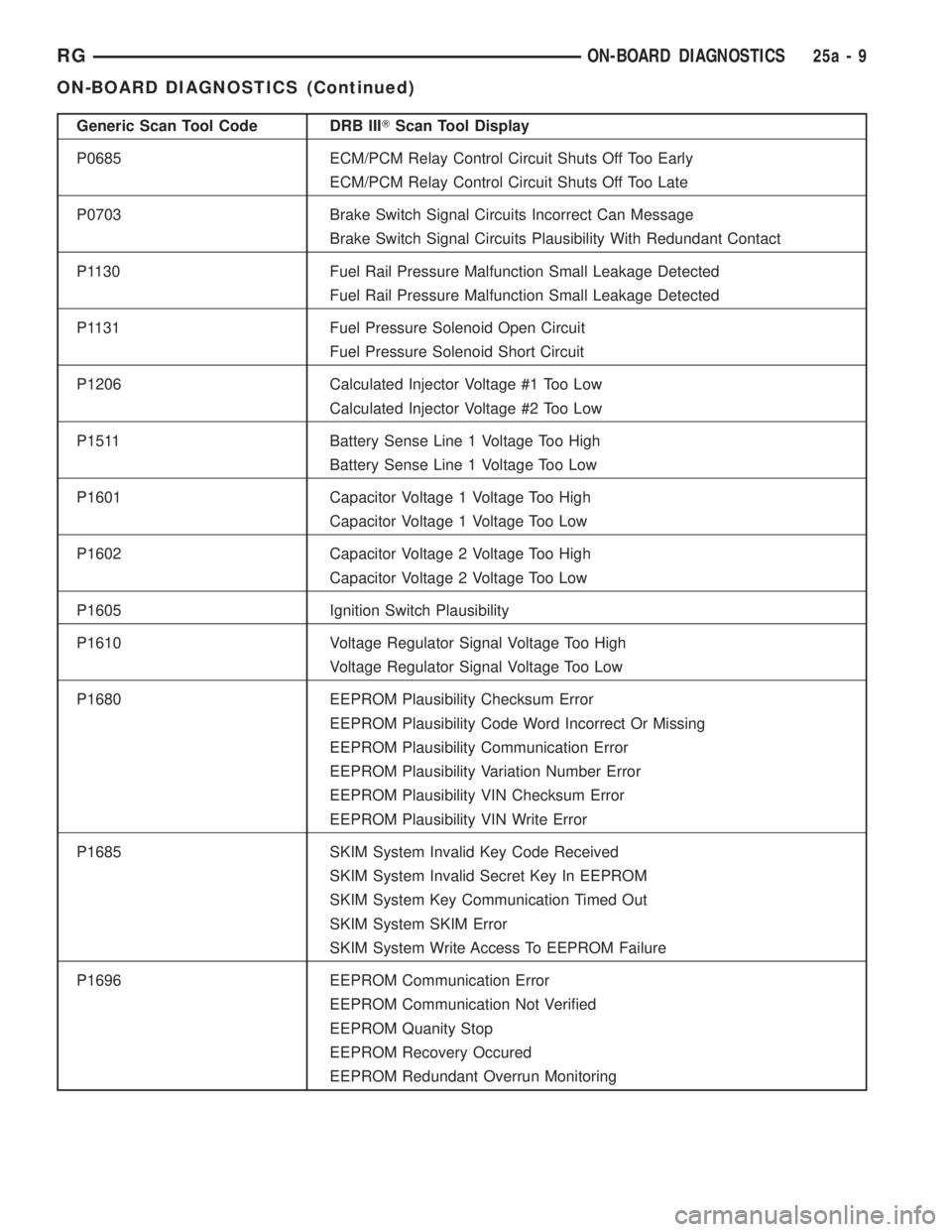
Generic Scan Tool Code DRB IIITScan Tool Display
P0685 ECM/PCM Relay Control Circuit Shuts Off Too Early
ECM/PCM Relay Control Circuit Shuts Off Too Late
P0703 Brake Switch Signal Circuits Incorrect Can Message
Brake Switch Signal Circuits Plausibility With Redundant Contact
P1130 Fuel Rail Pressure Malfunction Small Leakage Detected
Fuel Rail Pressure Malfunction Small Leakage Detected
P1131 Fuel Pressure Solenoid Open Circuit
Fuel Pressure Solenoid Short Circuit
P1206 Calculated Injector Voltage #1 Too Low
Calculated Injector Voltage #2 Too Low
P1511 Battery Sense Line 1 Voltage Too High
Battery Sense Line 1 Voltage Too Low
P1601 Capacitor Voltage 1 Voltage Too High
Capacitor Voltage 1 Voltage Too Low
P1602 Capacitor Voltage 2 Voltage Too High
Capacitor Voltage 2 Voltage Too Low
P1605 Ignition Switch Plausibility
P1610 Voltage Regulator Signal Voltage Too High
Voltage Regulator Signal Voltage Too Low
P1680 EEPROM Plausibility Checksum Error
EEPROM Plausibility Code Word Incorrect Or Missing
EEPROM Plausibility Communication Error
EEPROM Plausibility Variation Number Error
EEPROM Plausibility VIN Checksum Error
EEPROM Plausibility VIN Write Error
P1685 SKIM System Invalid Key Code Received
SKIM System Invalid Secret Key In EEPROM
SKIM System Key Communication Timed Out
SKIM System SKIM Error
SKIM System Write Access To EEPROM Failure
P1696 EEPROM Communication Error
EEPROM Communication Not Verified
EEPROM Quanity Stop
EEPROM Recovery Occured
EEPROM Redundant Overrun Monitoring
RGON-BOARD DIAGNOSTICS25a-9
ON-BOARD DIAGNOSTICS (Continued)
Page 3786 of 4284
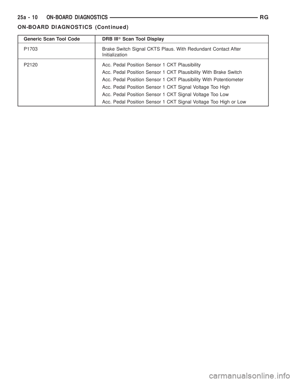
Generic Scan Tool Code DRB IIITScan Tool Display
P1703 Brake Switch Signal CKTS Plaus. With Redundant Contact After
Initialization
P2120 Acc. Pedal Position Sensor 1 CKT Plausibility
Acc. Pedal Position Sensor 1 CKT Plausibility With Brake Switch
Acc. Pedal Position Sensor 1 CKT Plausibility With Potentiometer
Acc. Pedal Position Sensor 1 CKT Signal Voltage Too High
Acc. Pedal Position Sensor 1 CKT Signal Voltage Too Low
Acc. Pedal Position Sensor 1 CKT Signal Voltage Too High or Low
25a - 10 ON-BOARD DIAGNOSTICSRG
ON-BOARD DIAGNOSTICS (Continued)